The requirement was clear: devise an alternative that bypasses the conventional hand-operated mechanism. Recognizing that our feet are just as capable when it comes to applying force in a precise manner—much like how we use them to operate pedals in a car—I decided to explore this avenue. I constructed a prototype using cardboard for the pedal, taking advantage of its availability and ease of manipulation, and copper for its conductive properties, essential for transferring the switch’s command.
A highlight of some code that you’re particularly proud of:
const int ledPin = 13; // LED connected to digital pin 13
const int touchSensorPin = 2; // Touch sensor (white wires) connected to digital pin 2

void setup() {
  pinMode(ledPin, OUTPUT); // Set the LED pin as output
  pinMode(touchSensorPin, INPUT_PULLUP); // Set the touch sensor pin as input with internal pull-up resistor
}

void loop() {
  // Check if touch sensor is touched (wires are connected)
  if (digitalRead(touchSensorPin) == LOW) {
    digitalWrite(ledPin, HIGH); // Turn on the LED
  } else {
    digitalWrite(ledPin, LOW); // Turn off the LED
  }
}
Video of Project:
Reflection and ideas for future work or improvements:
Reflecting on the process of creating my foot-operated light switch, I initially envisioned using aluminum for its excellent conductivity and lightweight properties. However, practical limitations often steer the course of innovation, and this project was no exception. With aluminum out of reach, I adapted to the materials available to me, selecting copper tape as a suitable alternative. This choice was not without its merits; copper’s conductivity is remarkable, and its flexibility proved invaluable during the assembly process.
The simplicity of the code was my saving grace, making the integration of electrical components less daunting than anticipated. Yet, every project presents its challenges. One such challenge was securing the wires in such a manner that they consistently made contact with the copper tape. Due to their placement, there were occasions when the connection was missed, disrupting the switch’s functionality. I recognized that increasing the copper tape’s surface area could potentially mitigate this issue, providing a more forgiving target for the wires to connect with.
For this week assignment, I have been thinking in how to properly implement it. I was thinking in using water, but none of the ideas that came into my mind were fun for me. I also think of using my eyes, but it was too uncomfortable, then I thought about the materials I had in my dorm, and I got reminded of the mask I have.
Not only that, but I have to admit that I generally do not come up with a plan, almost everything I do is spontaneous in a way. Therefore, following this methodology, I grabbed my mask and started in thinking in ways I can accomplish this task.
Materials
A 330-ohm resistor.
1 LED light (in this case is red).
A breadboard.
One red and two black jumper wires.
An Arduino board with a 5V and GND output.
A mask.
Cooper.
Tape.
Glue.
Something to hold the mask in a place.
Process
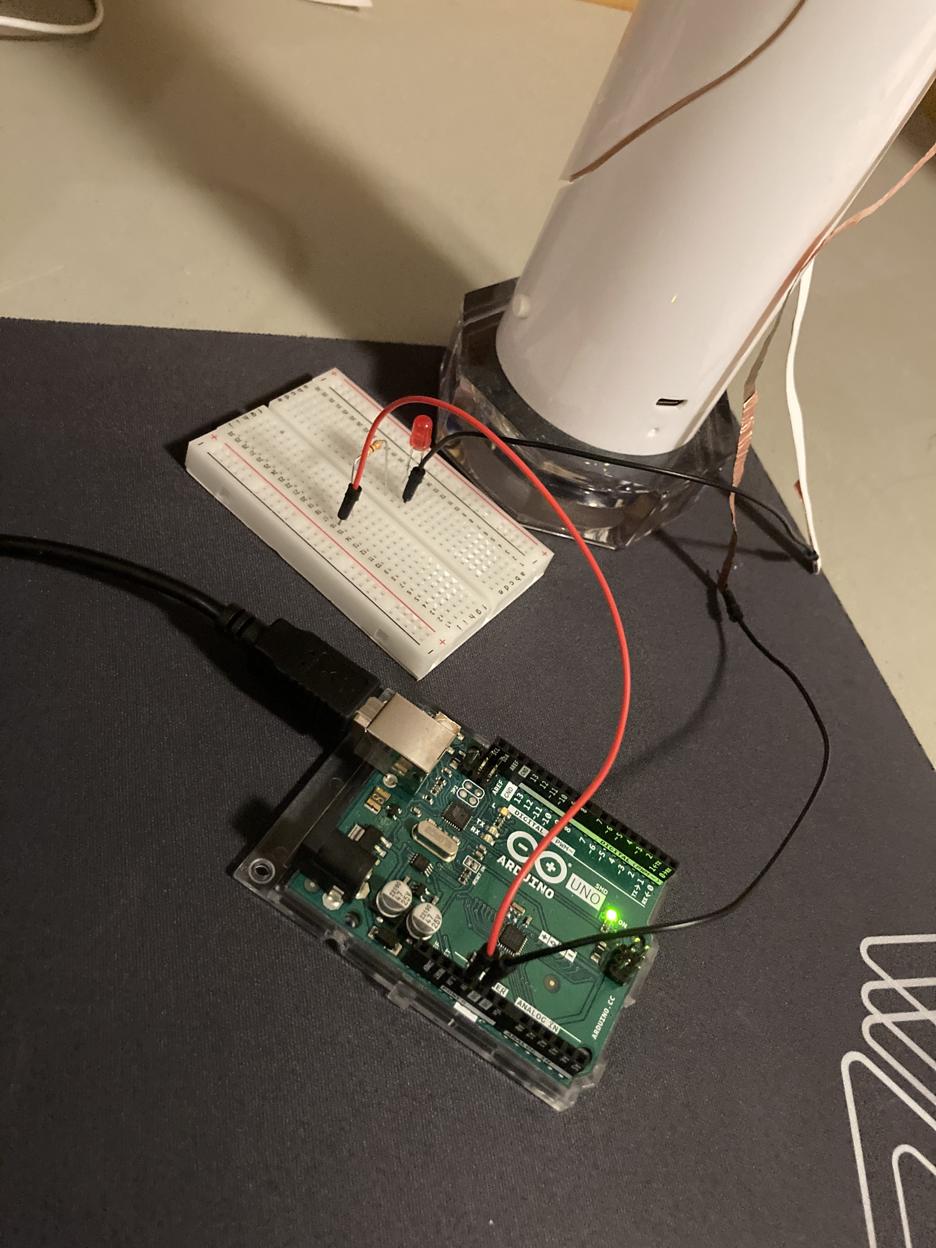
I needed to set up my Arduino first since, obviously, there would not be any result if it was not properly set up. Therefore, I created the basic connection that consisted in outputting 5V and GND with the use of the jumper wires, although only the red jumper wire was connected. The two black jumper wires were partially connected in order to create the bridge with the use of a conductive material; in this case, cooper.
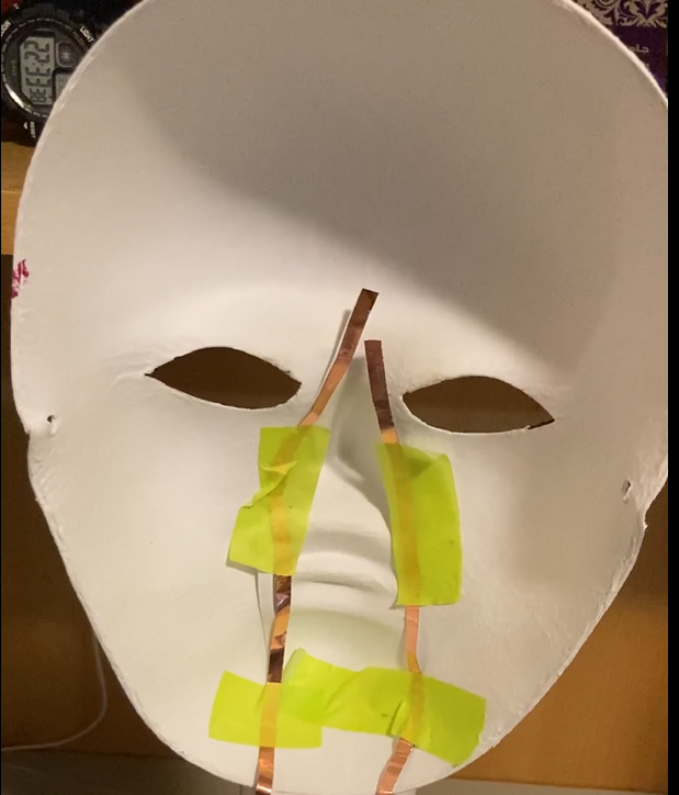
The mask needs to be prepared in the following way, with the use of cooper and tape:
Also, make sure that the cooper not only is held with tape on the mask, but that the cooper is long enough to paste the male connections of the jumper wires.
Once everything was connected to the breadboard. A resistor was placed in order to receive the positive connection to send to the red LED, and the male connections of the black jumper wires were glued into the loose cooper:
As for the way to create the bridge, there are several ways in which you can approach this. The idea here is to put on the mask without relying on the hands, and for this, I first I made sure that the mask was sitting in one place with the help of a base (in my case, my lamp). Following this, I taped my nose with some cooper in order that, once I put my face into the mask, the taped cooper on my nose would create the bridge and light up the red LED.
Showcase
Observe the following video to see how it operates:
Reflection
I am new to the world of Arduino, and while this is not the most elaborate work, I had fun making it. Yes, not using my hands limited my possibilities, but this comes at the benefit of actually trying to be even more creative. I am curious to see what are the next projects in the course, since I have seen some videos involving this device, although most of them were at the software level; the hardware level is a bit unknown for me.
To get started on the project, I was thinking if there is any object that I usually used. I started to look for any object that is used without the contact of my hands. The solution is my hat. Since the hat is the point of contact with the head and not with the hands, I decided to make a circuit around my hat. Therefore, as I wear my hat, the light will turn on.
Concept
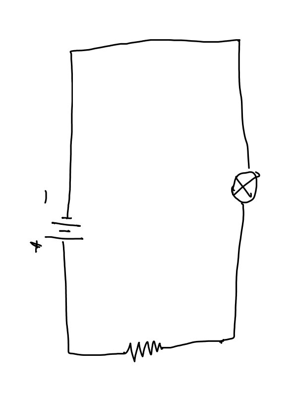
The hat switch uses the a simple circuit with the Arduino board, an LED light, a resistor, some aluminum foils along with battery to attach them on the hat. Below is the schematic of the circuit:
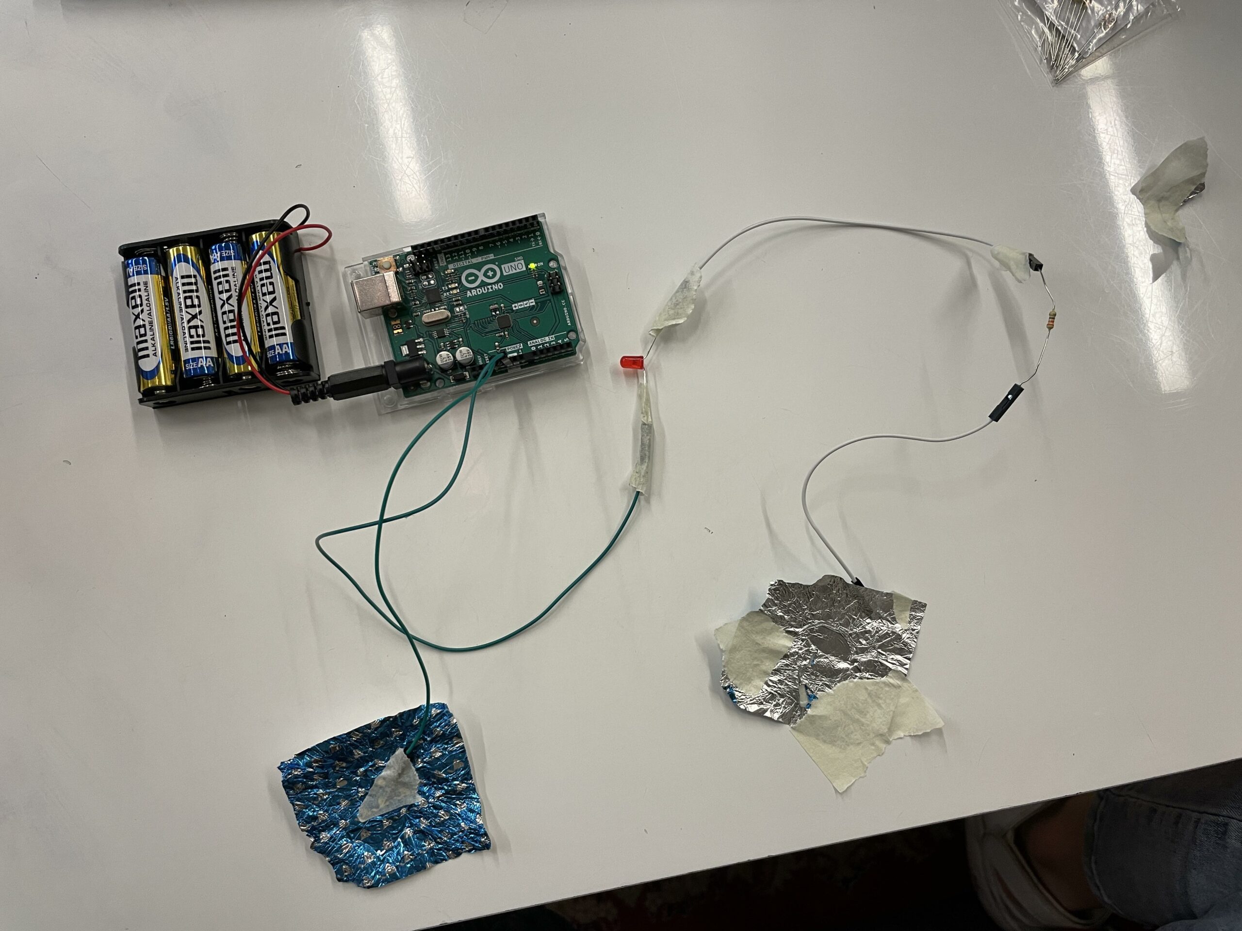
Below is the actual circuit after everything is connected:
implementation
Firstly, I connected the circuit together with the male-to-female wires so that I do not need to use the bread board. After making sure that everything is working properly, I start to attach the aluminum foils to the wires to increase the surface area of contact for the switch. Lastly, I attach everything to my head such that the aluminum foils are placed inside the hat and only come to contact if someone wears it. Below is the actual visualization of how the final product looks like:
Challenges
It was quite difficult to figuring out how I can attach the breadboard (which also along with the batteries and the Arduino board) to the hat. However, after I look around the IM labs “Consumables” to see what type of material they have, I noticed the different wires that can be connected together without the breadboard.
Reflection
It was a fun assignment that I have to think about the daily action that I could have done differently. Also, I also explore the possible resources that I have in the IM labs in the “Consumables” section.
What I want to improve on is how I can design the hat to be more aesthetic. The current version only have tapes and wires that can clearly be seen at the first glance. I would love to know how I can hide the wires for better design.
In this assignment, I was tasked with designing a unique switch that doesn’t use hands for activation. I embraced the challenge with creativity, creating two distinct switches: a water detection switch and a bicep flexion switch.
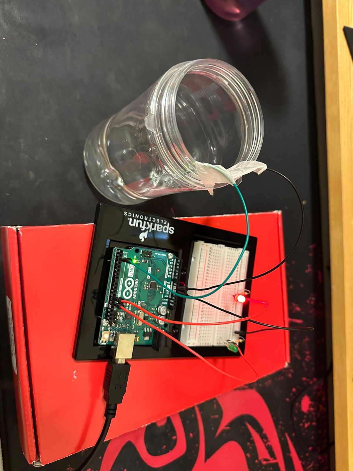
Switch 1: Water Detection System with Visual Indicator
Concept
The concept behind this water detection system is rooted in the fundamental principle of electrical conductivity in water. Utilizing a simple circuit design with an Arduino, the project aims to detect the presence or absence of water through basic electronic components. When water connects two strategically placed wires, it completes a circuit, allowing current to flow, which the Arduino interprets to trigger a visual signal.
Inspiration
The inspiration for this project came from the need to monitor water levels or detect water presence in various situations, such as checking if a plant needs watering or preventing overflow in tanks.
Image
Components Used
Arduino Uno
Green LED
Red LED
330Ω Resistors (2)
Jumper Wires
Breadboard
How It Works
I connected the anode of each LED (green and red) through a 330Ω resistor to digital pins 13 and 12 on the Arduino, respectively. The cathodes were connected to the ground (GND).
I prepared two wires as water sensors by stripping a small section of insulation off each end. One wire was connected to digital pin 2 on the Arduino, and the other wire was connected to GND. These wires were then placed close to each other but not touching, ready to be submerged in water.
I wrote and uploaded the code to the Arduino that checks the electrical connection between the sensor wires. If water is present (completing the circuit), the green LED turns on. If the circuit is open (no water detected), the red LED illuminates.
Video
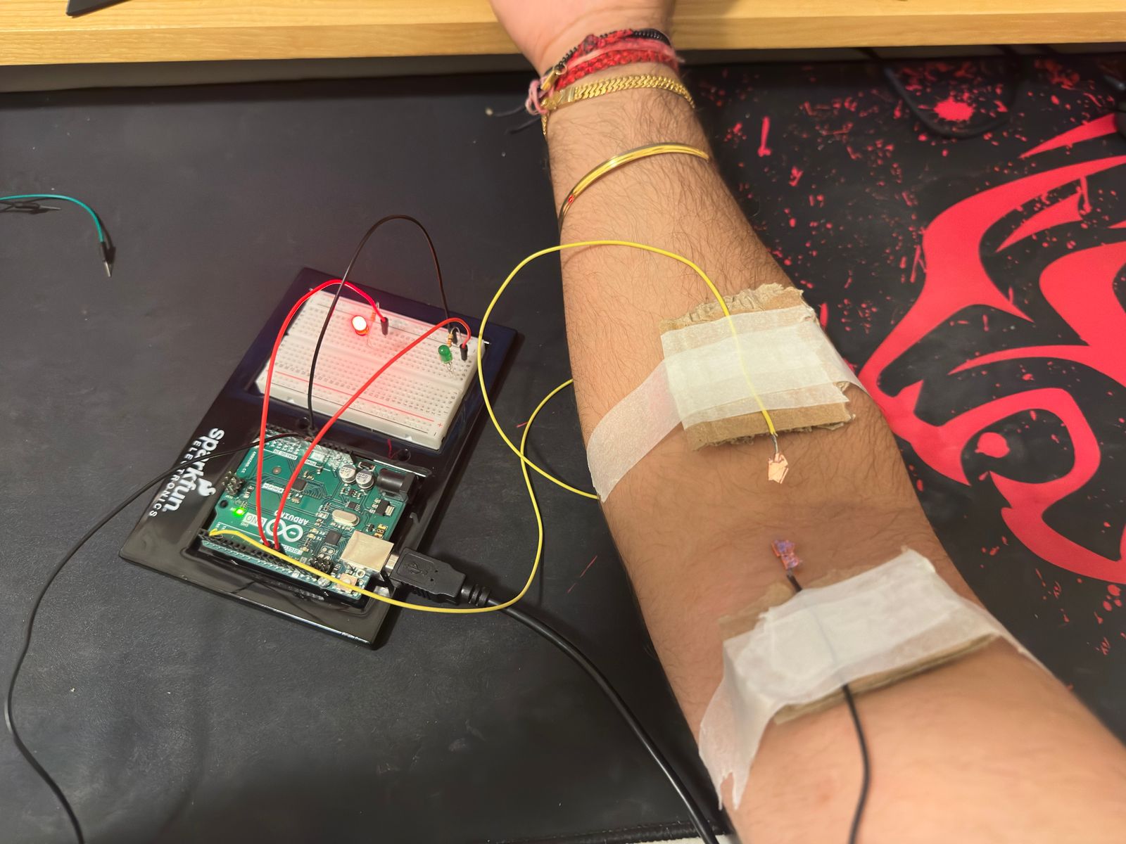
Switch 2: Bicep Switch
Concept
The goal was to create a device that could detect muscle flexion, particularly of the bicep, and provide immediate visual feedback.
The circuit setup and the code used are the same as the water detection switch.
Image
Components Used
Arduino Uno
Green LED
Red LED
330Ω Resistors (2)
Jumper Wires
Breadboard
Cardboard Pieces
Copper Tape
How It Works
When the bicep is flexed, the circuit completes, and the green LED lights up, indicating muscle activity. Conversely, when the muscle relaxes, the circuit breaks and the red LED turns on, indicating that the muscle is at rest.
For this assignment, I made a water-based switch. Thinking of a switch that does not use your hands is really tricky so I started thinking of conductors that could be easily placed and removed with a part of the human body that isn’t the hands. My mind immediately went to water – or well, technically, spit (essentially using your mouth to connect the circuit with water as a conductor).
Implementation
My circuit is based on the circuit we built in class with a switch whose state controls the action of an LED light. The Arduino code is simple, reading the state of the water switch and illuminating the LED if water is detected.
const int waterSwitchPin = 2;  // water switch digital pin
const int ledPin = 13;         // LED digital pin

void setup() {
  pinMode(waterSwitchPin, INPUT); // set water switch pin as input
  pinMode(ledPin, OUTPUT);        // set LED pin as output
  Serial.begin(9600);
}

void loop() {
  int waterSwitchPinState = digitalRead(waterSwitchPin); // read the state of water switch
  Serial.println(waterSwitchPinState);
  if (waterSwitchPinState == HIGH) { // water detected
    digitalWrite(ledPin, HIGH); // turn on LED
  } else { // no water detected
    digitalWrite(ledPin, LOW); // turn off LED
  }

}
To make the switch, I place two jumper wires in an empty bottle cap such that they are separated. I initially thought of just spitting water into the cap to create conductivity between the wires and turn the switch state to HIGH. However, Darko (thank you, Darko) rightfully pointed out that a true switch should also be switched off and suggested the use of a straw to lower the level of water in the cap and break the circuit. It was difficult to make sure the straw remained stable without using my hands but I managed to pull it off. I also had to use salt to make sure the water was ionized enough to conduct (thank you, Professor Aaron, for the trick!).
At first I wanted to create a switch that would act as a detector if someone opened a journal or a personal diary but upon finding out that we are not allowed to use hands I changed my entire idea. I thought it would be most interesting to use a material that does not typically associate with conductive plate image in our mind. After all, we are all taught how it’s dangerous to play around electronics and water due to its conductive properties (it’s poor but better than air). Surely we could use it for something good. One such application could be the implementation of a very small sensor near all cups, specifically designed for use by blind individuals to detect when their cup is getting full. This project is just a physically bigger version of such project involving following materials:
Materials
Piezoelectric speaker
Jumper wires
Aligator clips
Arduino Board
Power Bank
Cup
Water
Process
I decided to avoid using resistor at all since the audio produced by speaker wasn’t audible enough and would hardly activate by water touching the clips due to reduced voltage. I also decided to use salt mixed with water to improve conductivity and maximize the sound output. Realistically, if one were to transform this into a real project, we would be using cup integrated batteries, soldered electronics, built in sensor into the cup and any liquid substance. Even if conductivity is not terribly high, we could use a dedicated amplifier or a simple transistor.
At first I connected board to power-bank . I connected jumper wires to the board and alligator clips to jumper wires themselves. Piezoelectric speaker is part of the circuit and is directly mounted on bread board. The jumper wires leaving piezoelectric speaker are directly connected to alligator clips which are then connected to brim of the cup. When water is poured into a cup, at some point it touches the alligator clips and speaker makes highly audible buzz. This just so happens when water is about to overspill, providing the practical aspect of this project.
The idea of not using hands at all is a challenging one. I even thought about the aspect of indirect hand involvement. However, since it’s the rising water level that acts as a conductive plate and not a hand movement, I think conceptually it works just as well. The execution is pretty straightforward, with very simple design. Yet it tries to solve a realistic problem with minimum resources. In the future, this project could be expanded into an actual product, with more features, while trying to seamlessly integrate design into the cup.
For this assignment, I really struggled being creative, maybe because I’m fasting 🙂
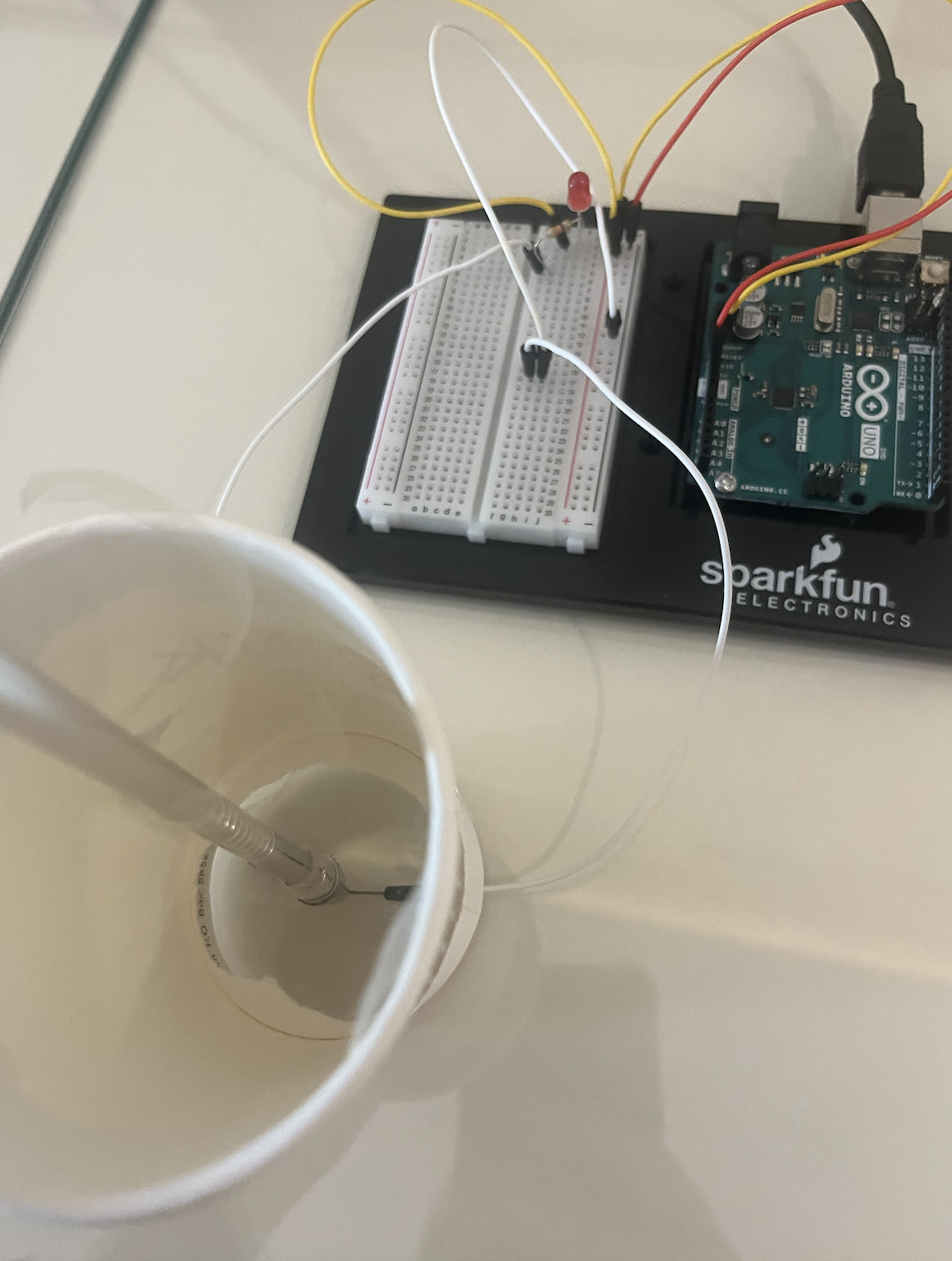
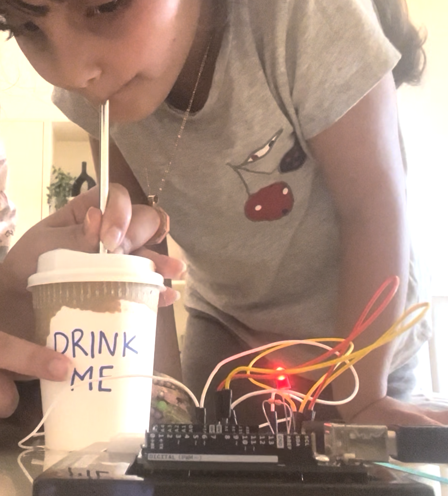
I explored various metals in my room to discover a novel method for illuminating an LED. Eventually, I decided to use a metal straw as the conductor between two wires. By placing it in a cup and using my mouth to press the straw onto the wires, the LED lights up.
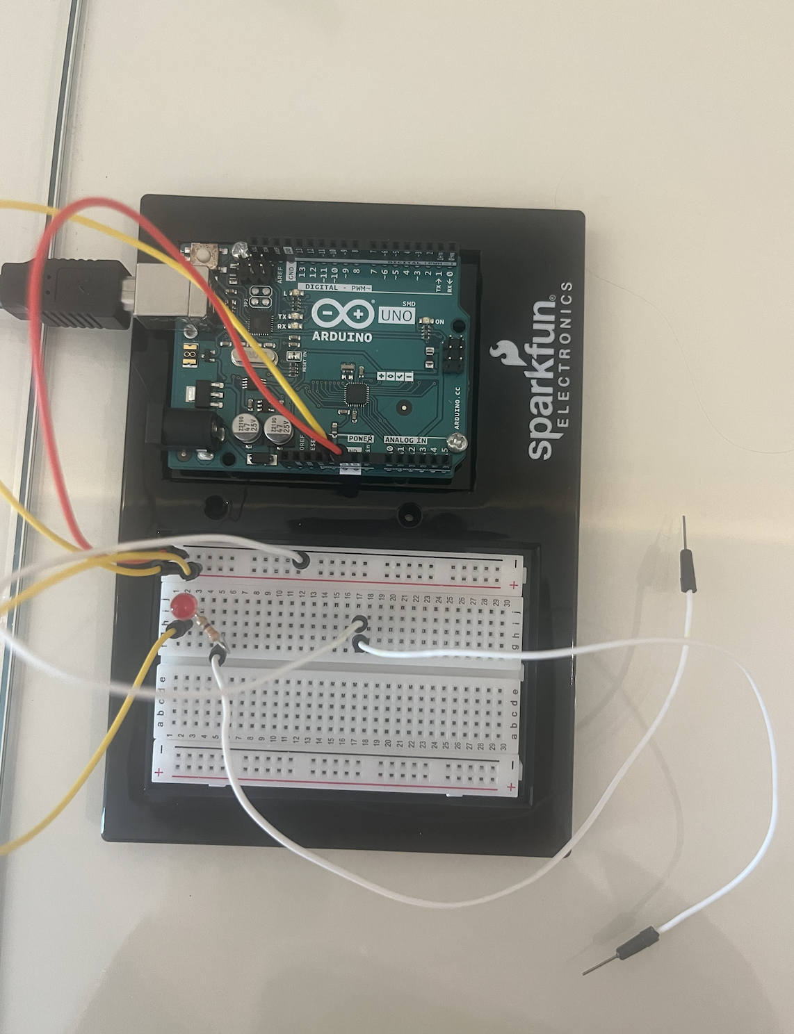
This is what my Arduino looked like:
Those two white wires were taped on the table, very close to each other but not touching.
I covered it with a cup to create the effect of drinking.
My niece volunteered to demonstrate this project. This is the LINK to the video
Lastly, this is my code:
const int ledPin = 2;      // Use pin 2 to control the LED
const int touchPin = 7;    // Use pin 7 to read the touch state

void setup() {
  pinMode(ledPin, OUTPUT);    // Initialize the LED pin as an output
  pinMode(touchPin, INPUT_PULLUP); // Initialize the touch pin as an input with internal pull-up resistor
}

void loop() {
  int touchState = digitalRead(touchPin); // Read the state of the touch pin

  if (touchState == LOW) {   // If wire A touches the wire on line 5, it will be LOW
    digitalWrite(ledPin, HIGH); // Turn on the LED
  } else {
    digitalWrite(ledPin, LOW);  // Turn off the LED
  }
}
I really enjoyed making this switch, and seeing it work at the end was truly rewarding.
Guitar is overrated 🎸😒. Anyone who got impressed by a electric guitar controlled cyberpunk game should seriously raise their standards.
When I am not working on brain controlled robots, I look after my child, called The Tale of Lin & Lang, which is a fictional universe where Industrial Revolution began in East Asia (China/Korea/Japan), and a re-imagination of alternative history. In that world, there are steampunk inventors who invent computers, clockwork, machines … and there are also artisans who plays the traditional bamboo flute (笛子 – dízi).
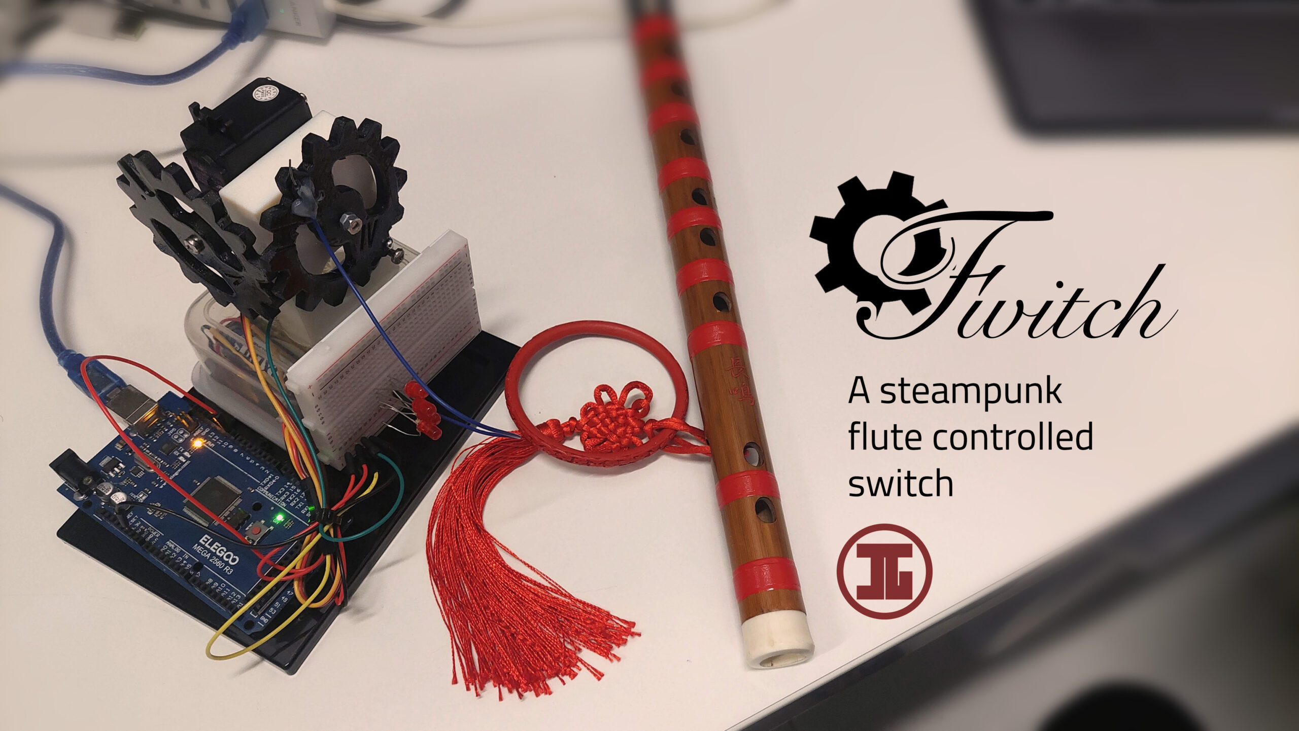
Well, that’s fiction…. or is it 🤔? Well, in real life, I am also a bamboo flute player and an inventor, and a steampunk enthusiast…. so I present Fwitch, a flute controlled steampunk switch.
Below is the complete demonstration.
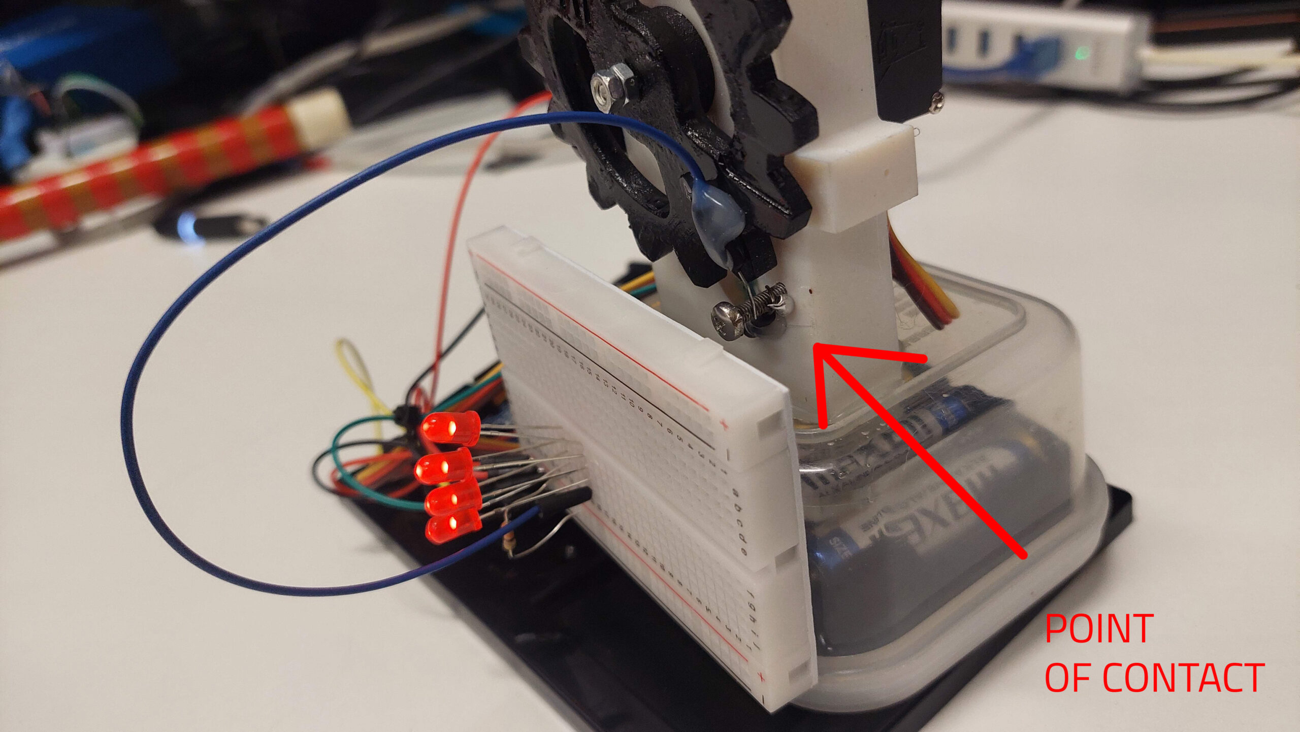
HOW IT WORKS
It’s a switch, so nothing complicated. One end of the wire needs to go and meet another wire… I am just driving the motion using 2 steampunk style gears I 3D printed and painted.
When I blow the flute, the laptop mic listens to my flute volume, and above a particular threshold, will establish a serial connection to arduino and tell the servo motor to rotate to a particular degree. And with another note from the flute, it will toggle the switch. Simple.
The servo I am using is quite large (because the gears are large), hence I need an external power supply. It is hidden in the container below to be neat and tidy.
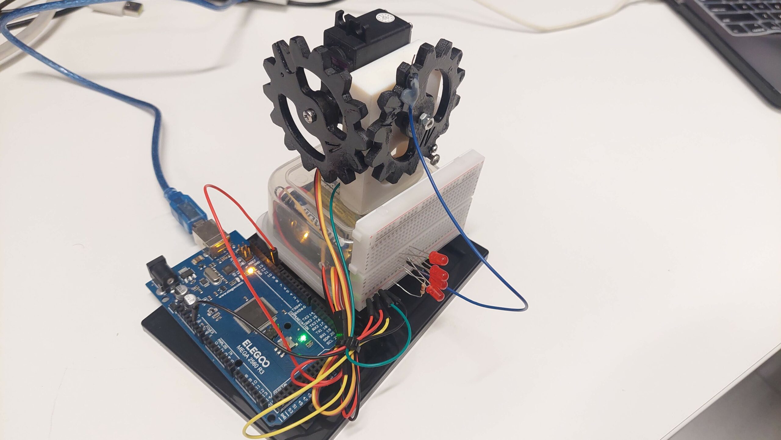
And yes, I am using a Chinese clone mega board.
Below are close up shots.
CODE
The following python code listens to the microphone on my computer, and above a particular volume threshold, it will send switch on and off signal through serial to arduino. I could have used a mic and do everything on arduino, but could not find one, so decided to use my laptop mic.
import pyaudio
import numpy as np
import os
import time
import serial
import serial.tools.list_ports

switch_on = False
volume_threshold = 30  # Configurable threshold
switch_toggled = False  # Flag to track if the switch was toggled

def clear_screen():
    # Clear the console screen.
    os.system('cls' if os.name == 'nt' else 'clear')

def list_serial_ports():
    ports = serial.tools.list_ports.comports()
    return ports

def get_volume(data, frame_count, time_info, status):
    global switch_on, switch_toggled

    audio_data = np.frombuffer(data, dtype=np.int16)
    if len(audio_data) > 0:
        volume = np.mean(np.abs(audio_data))
        num_stars = max(1, int(volume / 100))

        if num_stars > volume_threshold and not switch_toggled:
            switch_on = not switch_on
            ser.write(b'180\n' if switch_on else b'0\n')
            switch_toggled = True
        elif num_stars <= volume_threshold and switch_toggled:
            switch_toggled = False

        clear_screen()
        print(f"Switch:{switch_on}\nVolume: {'*' * num_stars}")

    return None, pyaudio.paContinue

# List and select serial port
ports = list_serial_ports()
for i, port in enumerate(ports):
    print(f"{i}: {port}")
selected_port = int(input("Select port number: "))
ser = serial.Serial(ports[selected_port].device, 9600)
time.sleep(2)  # Wait for serial connection to initialize
ser.write(b'0\n')  # Initialize with switch off

# Audio setup
FORMAT = pyaudio.paInt16
CHANNELS = 1
RATE = 44100
CHUNK = 1024

audio = pyaudio.PyAudio()

# Start the stream to record audio
stream = audio.open(format=FORMAT, channels=CHANNELS,
                    rate=RATE, input=True,
                    frames_per_buffer=CHUNK,
                    stream_callback=get_volume)

# Start the stream
stream.start_stream()

# Keep the script running until you stop it
try:
    while True:
        time.sleep(0.1)
except KeyboardInterrupt:
    # Stop and close the stream and serial
    stream.stop_stream()
    stream.close()
    ser.close()
    audio.terminate()
And this arduino part listens to the serial from python, and rotates the servo accordingly.
#include <Servo.h>

Servo myservo;
int val;

void setup() {
  myservo.attach(9);
  Serial.begin(9600);
  Serial.println("Servo Controller Ready");
}

void loop() {
  if (Serial.available() > 0) {
    String input = Serial.readStringUntil('\n'); // read the string until newline
    val = input.toInt(); // convert the string to integer

    val = constrain(val, 0, 180);

    myservo.write(val);
    Serial.print("Position set to: ");
    Serial.println(val);
    delay(15);
  }
}
Hope you enjoy.
Remarks
Well, since the assignment rubric required use of Arduino, I am using the Arduino. Had it been the original assignment without Arduino, things could have gotten more interesting 🤔. Arduino is a tool, transistors are tools. Many people are so inclined to believe that in order to implement a programmable logic, we need electronics.
🚫 NOOOO!!!!
My inner computer engineer says logic can be implemented anywhere with proper mechanism, and if you can implement logic, anything is a computer.
🧬 Human DNA is just a program to read lines of nucleobases and produce proteins based on that.
💧We can use water and pipes to implement logic gates and design our hydro switch.
🍳If I wanted to, even the omelette on my breakfast plate can be a switch.
We don’t even need 3 pin transistors , we can design purely “Mechanical” logic gates and design the switch. But oh well… putting back my celestial mechanics into my pocket.
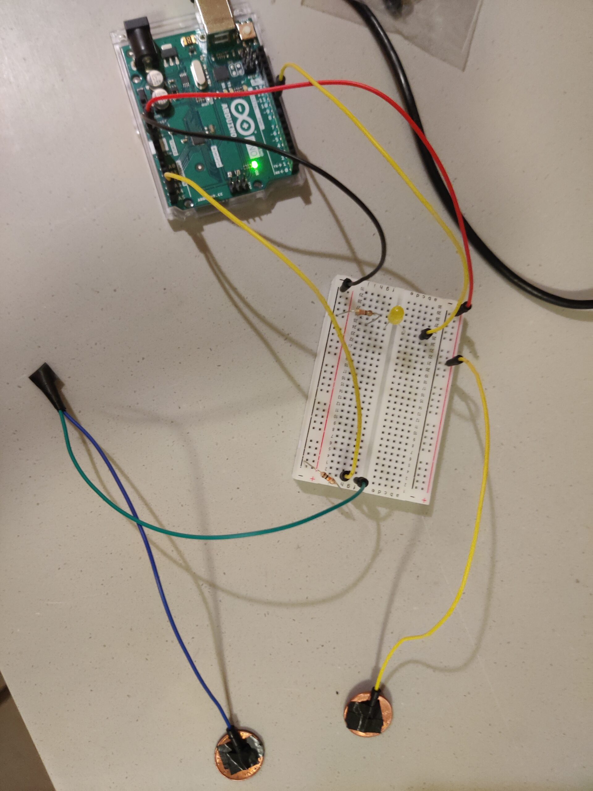
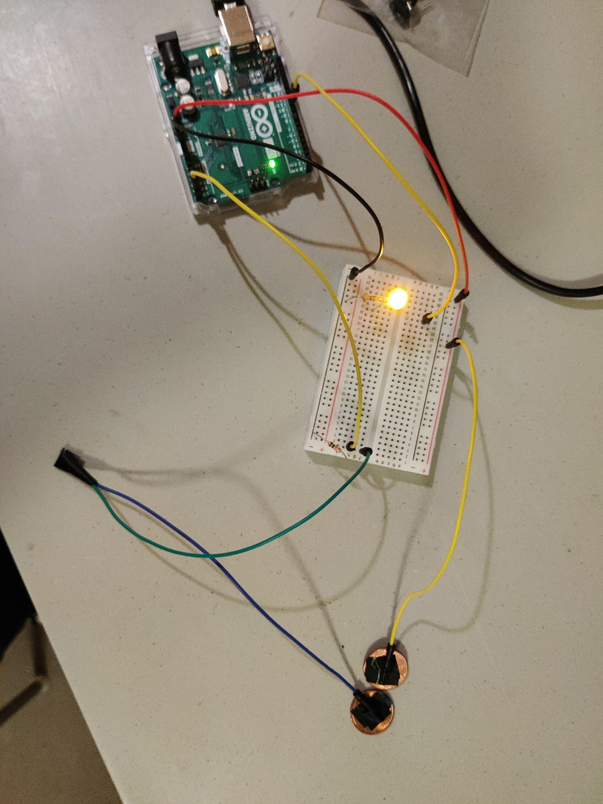
For the project, I was walking around my room and looking for creative ways to create a switch. Finally, I found two American pennies which are made from zinc and are coated with copper, both of which are good conductive materials. Then, I realized I could make a switch that works when the coins touch. Wires are taped to the coins so that when the coins touch, the circuit closes and lights up the yellow LED. I connected the green and blue wires together to extend the reach of the coins. The idea is similar to Carrom – the coin that has an extended reach has to be flung into the other coin which will be relatively stationary. The setup can be seen below.
Next, I write some code for the Arduino, so that when they touch, the LED stays lit for 3 seconds so that the contact is captured and a hit or miss can be seen clearly.
void setup() {
  // put your setup code here, to run once:
  pinMode(9, OUTPUT);
  pinMode(A5, INPUT);
}

void loop() {
  // put your main code here, to run repeatedly:
  int switchState = digitalRead(A5);

  if (switchState == HIGH){
    digitalWrite(9, HIGH);
    delay(3000);
  }
  else{
    digitalWrite(9, LOW);
  }
}
Ever since professor Sherwood told us about this assignment, I have started to think about how can I use my feet in order to make the LED light go on.
At first, I discovered that I need to use a sensor, which I found in the kit. Then, with a little inspiration from one of my favorite bands ever, Queen, I started to think about interactive ways to make this happen.
This was the result (excuse my PJs and slippers I was sick) :
At first, my right leg is right in front of the sensor. After the first few kicks, I move the right leg right next to the sensor, so that the LED light will turn off.
This was the code that I used:
//declaring the pins of the sensors
const int trigPin = 12;
const int echoPin = 13;
long duration;
int distance;

//declaring the rgb led
int rgb_r = 8;
int rgb_b = 7;
int rgb_g = 4;

void setup() {
  // put your setup code here, to run once:
  pinMode(echoPin, INPUT);
  pinMode(trigPin, OUTPUT);
  pinMode(rgb_r, OUTPUT);
  pinMode(rgb_b, OUTPUT);
  pinMode(rgb_g, OUTPUT);
  Serial.begin(9600);
}

void loop() {
  // put your main code here, to run repeatedly:
  digitalWrite(trigPin, LOW);
  delayMicroseconds(2);

  digitalWrite(trigPin, HIGH);
  delayMicroseconds(10);
  digitalWrite(trigPin, LOW);

  duration = pulseIn(echoPin, HIGH);
  distance = duration * 0.034 / 2;

  // We check the measured distance and control the RGB LED depending on it
  // If distance between 20-50 cm, LED is blue
    analogWrite(rgb_r, 0);
    analogWrite(rgb_g, 0);
    analogWrite(rgb_b, 255);
    Serial.println("Led is blue!");

  }

  delay(1000);
  Serial.print("distance = ");
  Serial.print(distance);
  Serial.print("\n");
  delay(1000);
}
It would have been complete if I added the hand claps with the kicks for sound purposes but I did not want to be taxed for that in regards to my grade 🙂 .
Overall, it was fun to make. The sensor is not that strong so in the future I would like to use something stronger maybe. Also, this can become an actual project and I could make it so that the color of the led would change when your feet have different positions.