Concept
After completing my project, I began contemplating a creative concept for it. It occurred to me that if I had a child, I would use this project as a toy to help them quickly learn colors. Consequently, I decided to name this project the “Interactive Color Toy.” Children can use it as a toy, pressing a button to cycle through three colors: red, yellow, and green. Additionally, they can adjust the LED’s brightness using a potentiometer. By pressing the button and changing the brightness, children could easily learn colors through tactile experiences, especially if parents help by naming the colors that appear when the button is pressed.
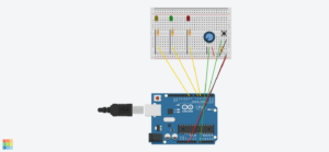
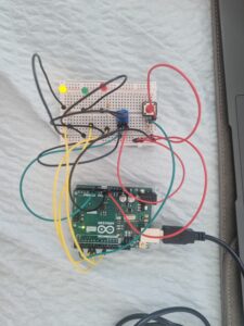
My circuit consists of the following elements:
– Arduino board (e.g., Arduino Uno)
– Potentiometer
– Push button switch
– LED
– Resistors
– Breadboard
– Jumper wires
In this circuit, a potentiometer is connected to an analog input pin of the Arduino, allowing it to read varying voltage levels. A push button is connected to a digital input pin, enabling the Arduino to detect button presses. Three digital output pins are connected to the red, green, and yellow pins of the LED, respectively. By adjusting the potentiometer, users control the brightness of the LED colors, while pressing the button cycles through the available colors.
Code
// Pins
const int POTENTIOMETER_PIN = A0; // Analog input pin for potentiometer
const int BUTTON_PIN = 2; // Digital input pin for push button
const int RED = 5;  // Digital output pin for RGB LED (red)
const int GREEN = 6;  // Digital output pin for RGB LED (green)
const int YELLOW = 9; // Digital output pin for RGB LED (yellow)

// Variables
int potentiometerValue = 0; // Potentiometer value
bool buttonState = false; // Button state
int colorIndex = 0; // Index of current color

void setup() {
  pinMode(POTENTIOMETER_PIN, INPUT);
  pinMode(BUTTON_PIN, INPUT_PULLUP);
  pinMode(RED, OUTPUT);
  pinMode(GREEN, OUTPUT);
  pinMode(YELLOW, OUTPUT);
}

void loop() {
  potentiometerValue = analogRead(POTENTIOMETER_PIN);

  // Map potentiometer value to LED brightness
  int brightness = map(potentiometerValue, 0, 1023, 0, 255);

  // Set the LED color based on the current color index
  switch (colorIndex) {
    case 0:  // Red
      analogWrite(RED, brightness);
      analogWrite(GREEN, 0);
      analogWrite(YELLOW, 0);
      break;
    case 1:  // Green
      analogWrite(RED, 0);
      analogWrite(GREEN, brightness);
      analogWrite(YELLOW, 0);
      break;
    case 2:  // Yellow
      analogWrite(RED, 0);
      analogWrite(GREEN, 0);
      analogWrite(YELLOW, brightness);
      break;
  }

  // Check button state
  if (digitalRead(BUTTON_PIN) == LOW) {
    if (!buttonState) {
      // Toggle color index
      colorIndex = (colorIndex + 1) % 3;
      buttonState = true;
      delay(200);
    }
  } else {
    buttonState = false;
  }
}
This is my code. The analogRead function reads the value from the potentiometer, which is then mapped to control the brightness of the LED colors. The switch statement selects the appropriate color based on the current color index, and the digitalWrite function sets the brightness of the corresponding LED pins accordingly. When the button is pressed, the color index is incremented to cycle through the available colors.
Improvements and Overview
Overall, I enjoyed this assignment, particularly the aspect of controlling outputs using different physical inputs. The most challenging part was figuring out how the current moved through the circuit. However, I was able to easily determine the correct way to connect all the components. As a further improvement, I considered expanding the color palette by using a full RGB LED instead of individual colors. This would allow for a wider range of colors and more creative possibilities.


