
Introduction
For this assignment I really wanted to use Ultrasonic sensor and experiment with its detecting capabilities, hence the name of the project – multi-detector. I wanted to have three separate distances: near, medium, far to have different activations. (For example, different lights or sounds). To satisfy projects requirement (analog input/output + digital input/output) I decided to implement other elements since ultrasonic can be considered as both. This enabled me to expand project and make it more interactive. I decided to add RGB LED as an analog output source which in itself is based on ultrasonic sensor readings. A digital output LED in this case would be the status LED which is activated by digital input slider switch. Conversely, the status is also indicated by short lasting sound by second piezo speaker. The analog input is my potentiometer which controls the pitch of the buzzer. As you can see we have more than one digital/analog inputs and outputs and making sure they all work well together in a sensible manner was the main goal of this project.
Process:
The design is quite intuitive. User can turn on the sensor which is indicated by blue led briefly lit up and brief sound played by second piezo speaker. Then user can point the ultrasonic sensor at different objects. RGB LED will light up in different colors based on the distance to that object. For far distances I am using green light, for medium – yellow and for close red. I decided to use RED for close along with buzzing sound to demonstrate a state of emergency, something that is often used in real life applications. Providing both striking visual stimulus (RED color) and audio (high pitch sound) signals the user of proximity in urgent manner. This might be useful for larger scale projects where detection of a foreign object has to be alerted to user at all costs.
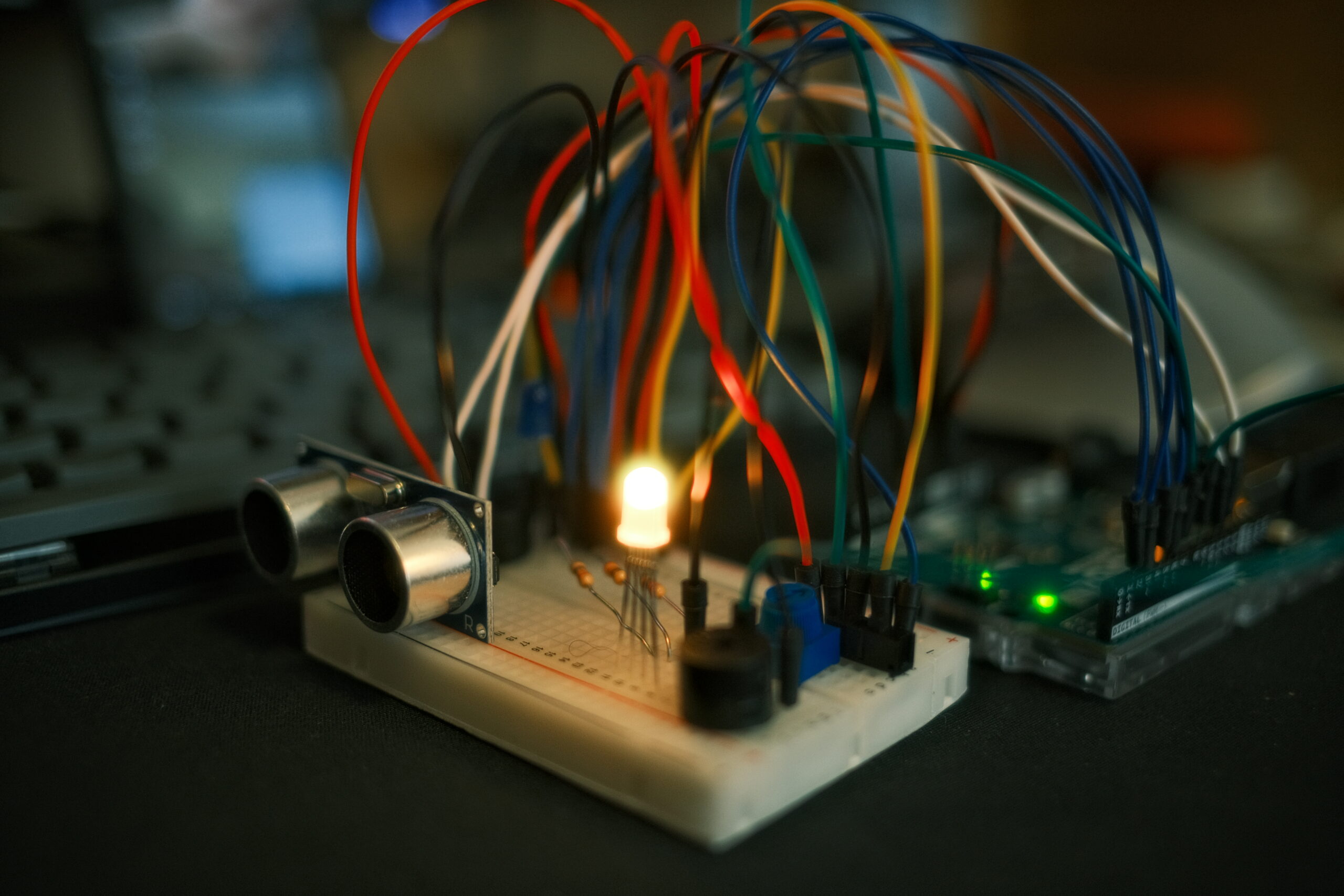
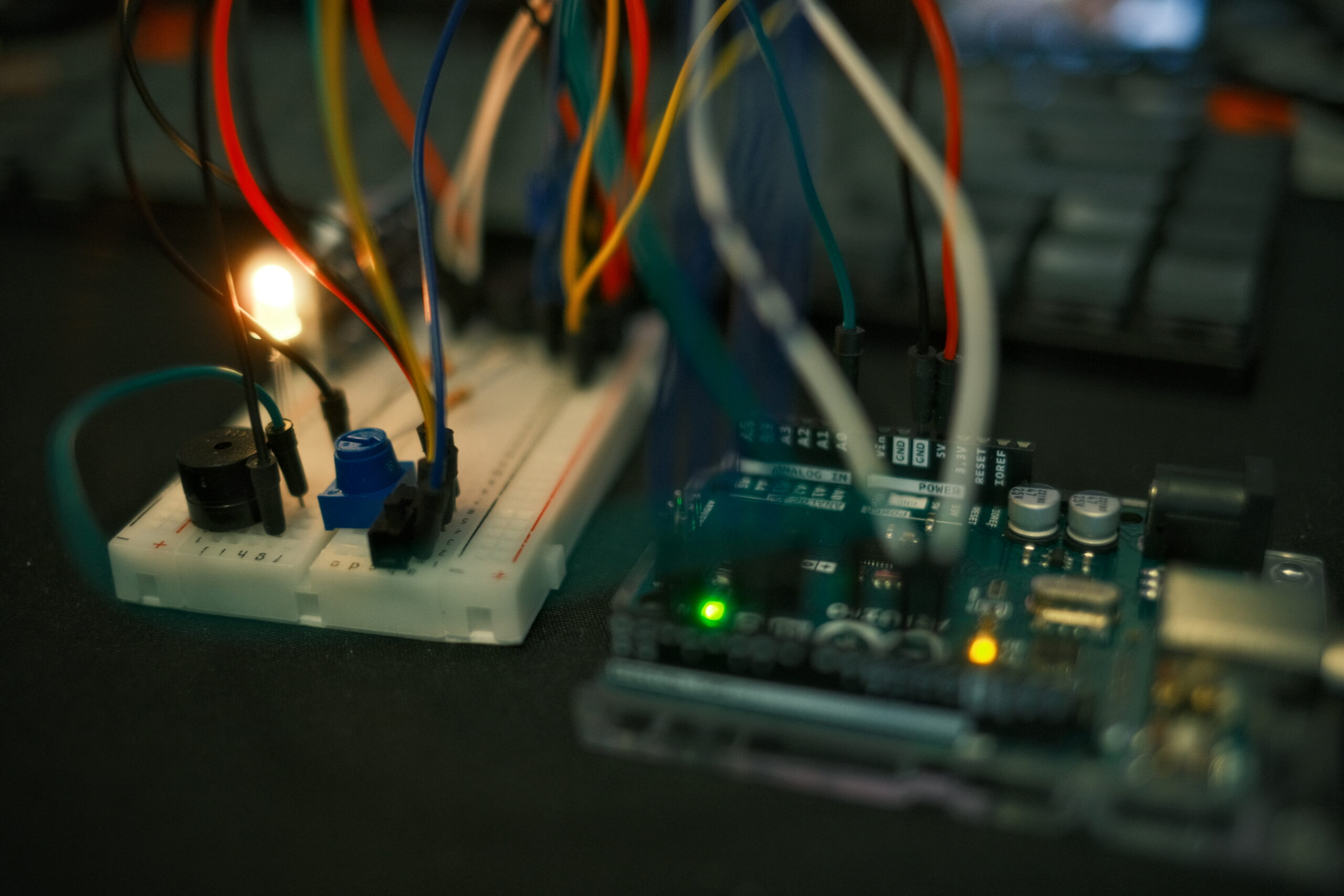
I used Tinkercad for simulating my project online and as seen on the video below, it works perfectly fine: (I tried to rearrange objects for best visibility possible).
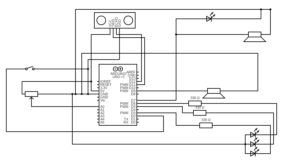
I am also including a diagram form Tinkercad conversion which did not look fully proper with incomplete connections and questionable alignments, hence I used Circuit Diagram Web Editor to draw design myself from scratch (ultrasonic is in center since it has both inputs and outputs). For the future assignment I will only use whichever is most appropriates based on your feedback.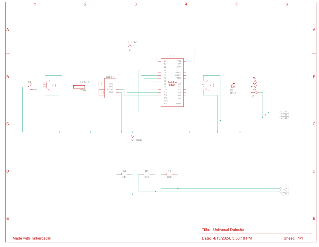
Code:
// pin connections
const int trigPin = 11;               // Pin connected to the trigger pin on the ultrasonic sensor
const int echoPin = 12;               // Pin connected to the echo pin on the ultrasonic sensor
const int redPin = 3;                 // Pin to control the red LED inside the RGB LED
const int greenPin = 5;               // Pin to control the green LED inside the RGB LED
const int bluePin = 6;                // Pin to control the blue LED inside the RGB LED
const int piezoPin = 9;               // Pin for the first piezo speaker (used for siren)
const int potPin = A0;                // Analog pin connected to the potentiometer
const int switchPin = 2;              // Digital input pin for the switch
const int secondPiezoPin = 7;         // Pin for the second piezo speaker (used for feedback on switch toggle)

float distance = 0;                   // to store the measured distance
bool lastSwitchState = HIGH;          // to track the last state of the switch

void setup() {
  Serial.begin(9600);

  // Set pin modes
  pinMode(trigPin, OUTPUT);
  pinMode(echoPin, INPUT);
  pinMode(redPin, OUTPUT);
  pinMode(greenPin, OUTPUT);
  pinMode(bluePin, OUTPUT);
  pinMode(piezoPin, OUTPUT);
  pinMode(secondPiezoPin, OUTPUT);
  pinMode(potPin, INPUT);
  pinMode(switchPin, INPUT_PULLUP);   // internal pull-up resistor for the switch
}

void loop() {
  bool currentSwitchState = digitalRead(switchPin); // read the current state of the switch

  // check if the switch state has changed
  if (currentSwitchState != lastSwitchState) {
    if (currentSwitchState == LOW) {
      // plauy a brief sound on the second piezo speaker when the switch is toggled
      tone(secondPiezoPin, 1000, 200); //  a 1000 Hz tone for 200 milliseconds
    }
    lastSwitchState = currentSwitchState; // Update the last known state of the switch
  }

  // actions when the switch is active
  if (currentSwitchState == LOW) {
    distance = getDistance(); //  distance - ultrasonic sensor

    Serial.print(distance);
    Serial.println(" in");

    //  RGB LED control
    if (distance <= 10) {
      analogWrite(redPin, 255);       // Close distance - turn RGB LED red
      analogWrite(greenPin, 0);
      analogWrite(bluePin, 0);
      playSiren();                    // siren on
    } else if (distance > 10 && distance < 20) {
      analogWrite(redPin, 255);       // Medium distance - turn RGB LED yellow
      analogWrite(greenPin, 50);
      analogWrite(bluePin, 0);
      noTone(piezoPin);               // Stop siren
    } else {
      analogWrite(redPin, 0);         // Far distance - turn RGB LED green
      analogWrite(greenPin, 255);
      analogWrite(bluePin, 0);
      noTone(piezoPin);               // Stop siren
    }
  } else {
    // Turn off all outputs when the switch is not active
    analogWrite(redPin, 0);
    analogWrite(greenPin, 0);
    analogWrite(bluePin, 0);
    noTone(piezoPin);
  }

  delay(50);  // Short delay to stabilize readings
}

// Function to measure distance using ultrasonic sensor
float getDistance() {
  digitalWrite(trigPin, HIGH);
  delayMicroseconds(10);
  digitalWrite(trigPin, LOW);

  float echoTime = pulseIn(echoPin, HIGH);
  return echoTime / 148.0;  // Convert time to distance
}

// control siren based on distance
void playSiren() {
    int potValue = analogRead(potPin);  // read the potentiometer value
    int volume = map(potValue, 0, 1023, 0, 255);  // Map it to PWM range
    analogWrite(piezoPin, volume);  // control volume


}
In the setup() function, each component is initialized to its respective pin mode, ranging from outputs for LEDs and piezo speakers to inputs for the ultrasonic sensor and potentiometer. The main loop() continuously checks the state of a digital switch to control the overall system operation, toggling functionality and triggering a brief alert sound from a secondary piezo speaker upon state changes. Distance is measured using an ultrasonic sensor, with the results dictating the color output of an RGB LED and the activation of a siren on the primary piezo speaker, whose volume is adjusted by a potentiometer. Everything else I already discussed in introduction and commented in the code. As you can see it is quite extensive so hopefully it should answer all your questions.
Demonstration:
Challenges:
While integrating the various components in this project, I faced some interesting challenges. Managing the piezo speaker’s volume with analogWrite() proved to be tricky because the function doesn’t directly control voltage output but instead modulates the PWM signal, which isn’t ideal for driving piezo speakers. I followed a tutorial for setting up an ultrasonic sensor from Sparkfun itself so that was fairly straightforward. I tried my best to manage the colors of the cables properly but eventually, I ran out of black wires so I used yellow as a substitute. Redrawing schematic was not as much challenging as it was time consuming. In the future, I would like to find a faster way to do this while satisfying project requirements.
Reflection:
All in all, I am quite happy with how my project turned out. I think what I learned through this project might be very useful for my future assignments and final project since I learned more about digital/analog inputs outputs as presented in Arduino, as well as reading/creating schematics and testing out project both in simulation and in real world. This project could easily be expanded by incorporating more components and making it part of something bigger since its sole responsibility for now is just detection.