Week 9 – Arduino: analog and digital inputs & outputs

My Concept: I wanted to create a circuit in which the push button turns LED1  on and off and the photoresistor regulates the LED2 by turning on, making it blink and turning off based on the value of the photoresistor.

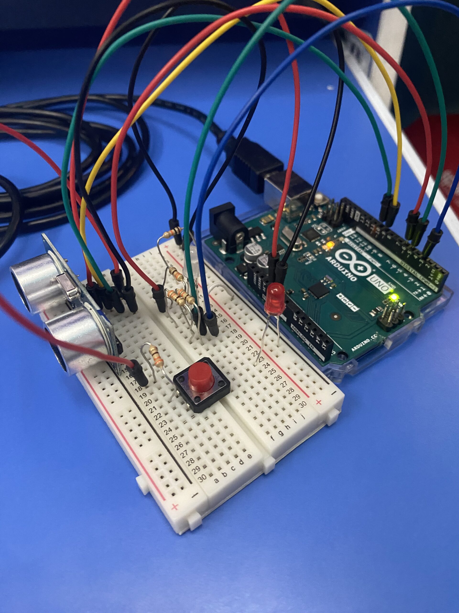
The video of the work: arduino_video

The code on Arduino:

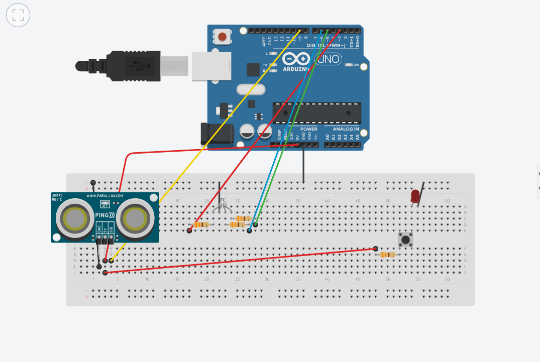
The example with three push buttons controlling three LEDs on the website https://microdigisoft.com/controlling-leds-with-multiple-push-button-using-arduino/ was used in creating a circuit with one push button and one photoresistor with two LEDs.

//initializing the pins to push button and photoresistor 
const int BUTTON1 = 2; 
const int PHOTOSENSOR = A0;
//initializing the pins to LED1 and LED2
const int LED1 = 8;
const int LED2 = 12;

int BUTTONstate1 = 0;
int PHOTOSENSORvalue = 0; 

void setup()
{
//defining the button (digital) and photoresistor (analog) as input pins
  pinMode(BUTTON1, INPUT); 
  pinMode(PHOTOSENSOR, INPUT);
//defining LEDs as output pins
  pinMode(LED1, OUTPUT);
  pinMode(LED2, OUTPUT);
}

void loop()
{
//the conditional to turn on the LED1 if the button is pushed
  BUTTONstate1 = digitalRead(BUTTON1); 
  if (BUTTONstate1 == LOW)
  {
    digitalWrite(LED1, HIGH);
  }
  else
  {
    digitalWrite(LED1, LOW);
  }

//the conditional to turn on the LED2, make it blink and turn off based on the value on photoresistor
  PHOTOSENSORvalue = analogRead(PHOTOSENSOR);
  if (PHOTOSENSORvalue < 500)
  {
    // Low light condition which turns LED2 on
    digitalWrite(LED2, HIGH);
  }
  else if (PHOTOSENSORvalue >= 500 && PHOTOSENSORvalue < 1000)
  {
    // Medium light condition which makes the LED2 blink
    digitalWrite(LED2, HIGH); 
    delay(500); 
    digitalWrite(LED2, LOW); 
    delay(500); 
  }
  else
  {
    // High light condition which turns LED2 off
    digitalWrite(LED2, LOW);
  }
}

I am particularly proud of the code with reads the value of the photoresistor and gives the LED outputs accordingly (turn on, blink, turn off).

Reflections: This work might seem easy, but took lots of research and understanding of the concept. Initially, my idea was to control the brightness of LED2 based on the resistance value on the photoresistor to show that the LED2 is an analog output. However, strangely, LED1 was affected by the value of the photoresistor and LED2 did not react. Then, I changed the code to make the LED2 turn on when the value of the photoresistor is less than 500 ohms, blink when it is in the range of [500, 10000) and turn off when these conditions are not met. As this one worked well, I used this code. Nevertheless, I would like to solve the mystery of the first outcome.

reading reflection: week 9

Making Interactive Art: Set the Stage, Then Shut Up and Listen reads like meta commentary for this class. For all the work that we have done in the past weeks, we’ve produced supporting documentation backing our inspiration, thought process, methodology, and everything in between. The author speaks of such artists with disdain. “They pre-script what will happen. When you do that, you’re telling the participant what to think, and by extension, how to act. Is that what you wanted?” That is actually not what I want, and for my final project, I would like to work on this author’s terms. I don’t have an idea for my final project yet, but I think I want to create something expansive; something that houses at least the potential for serendipity. The projects that I am making right now are rather limited in functionality, so essentially I have already defined the scope for interactivity before the first interaction with my projects can even happen. But my goal for my final project is to design, for each individual user, unique experiences which exist in a larger permutative space.

The other reading offers some good ideas for thinking in this direction. Furthermore, even though most of the works listed are popular project ideas in the interactive art community, I liked how the author addressed this at the get-go. “So if you’re new to physical computing and thinking to yourself “I don’t want do to that, it’s already done,” stop thinking that way! There’s a lot you can add to these themes through your variation on them.” Usually, when I’m looking for inspiration on the blog for my weekly projects, I look at other people’s work and immediately close off ideas pertaining to the use of similar tools or methods. But looking at projects that use “body-as-cursor” or “hand-as-cursor”, it seems I don’t have to be that restrictive in my thinking. Everyone used Javascript to create all these cool projects in the first half of the semester — but every project came out so unique and with the emblem of each person’s individuality. So, if I see someone using an LDR for their project, I don’t think I should turn away from using LDRs in my project altogether. I can also probably make something cool with the same tools.

Week 9 Assignment: Crossroad Warning Sensors

Concept:

In this week’s assignment, I have utilized the analog output features. From all the knowledge that I have gained from the classes, I have decided to create a prototype that shows drivers how far they are from the crossroad walking area in front of the signals. I decided to pursue this assignment because I noticed that there are a lot of people who get way too close to the crossroad walking which will interfere with the individual’s path and can be dangerous in some instances. The way the prototype warns the drivers is by portraying an LED output under the signal for each lane, if the driver is at a good distance, it shows green and the closer they the color fades into yellow, and finally into the red region where if the driver gets too close to the crossroad, it will illuminate a bright red LED showing that they shouldn’t go anywhere after that point. If the driver goes into the red region, there’s an option for the pedestrians to click a button on the pole to warn the driver to back off by illuminating the red light.

Prototype:

I used the ultrasonic sensor to detect the distance, and a common cathode LED to create green, red, and yellow colors in one LED. For the pedestrian warning button, I used a push button that connects the circuit to an external LED which will switch on with each push of a button.

Code:

const int trigPin = 9;
const int echoPin = 10;
const int bluePin = 6;
const int greenPin = 5;
const int redPin = 3;

// Declare variables for LED colors
int redValue = 0;
int greenValue = 0;
int blueValue = 0;

void setup() {
//initiate pins as inputs and outputs depending on its application
  Serial.begin(9600);
  pinMode(trigPin, OUTPUT);
  pinMode(echoPin, INPUT);
  pinMode(redPin, OUTPUT);
  pinMode(greenPin, OUTPUT);
  pinMode(bluePin, OUTPUT);
}

void loop() {
//sends a short pulse of ultrasonic sensor and waits a bit then receives it
  digitalWrite(trigPin, LOW);
  delayMicroseconds(2);
  digitalWrite(trigPin, HIGH);
  delayMicroseconds(10);
  digitalWrite(trigPin, LOW);

//Time it takes for the pulse to travel back from the object
  long duration = pulseIn(echoPin, HIGH);
//Universal conversion of time into distance in cm
  int distance = duration * 0.034 / 2;
  int brightness = 0;

//If conditions to produce light at specific distances
 if (distance < 10) {
  brightness = map(distance, 3, 10, 255, 0);
  //RED COLOR
  analogWrite(redPin, brightness);
  analogWrite(greenPin, 0);
  analogWrite(bluePin, 0);

} else if (distance >= 10 && distance < 20) {
  brightness = map(distance, 10, 20, 0, 255);
  //YELLOW COLOR
  analogWrite(redPin, brightness);
  analogWrite(greenPin, brightness);
  analogWrite(bluePin, 0);

} else if (distance >= 20 && distance <= 50) {
  brightness = map(distance, 20, 50, 0, 255);
  //GREEN COLOR
  analogWrite(redPin, 0);
  analogWrite(greenPin, brightness);
  analogWrite(bluePin, 0);

} else {
  // Default color
  setColor(0, 0, 0);  
}

//output codes to know what distance I am at as well as the proportionate RGB color
  Serial.print("Distance: ");
  Serial.print(distance);
  Serial.print(" cm | RGB Color: ");
  Serial.print("R: ");
  Serial.print(redValue);
  Serial.print(" G: ");
  Serial.print(greenValue);
  Serial.print(" B: ");
  Serial.println(blueValue);

  delay(20);
}

Reflection:

Overall, I learned a lot about the use of analog inputs/outputs and how digital pins differentiate from analog ones. Some of the difficulties I have faced were probably more on the code than the setup. Such as the mapping of the distance of the ultrasonic sensor to the LED’s increasing/decreasing brightness. Another issue was the conversion of time into distance, after looking through Google, I found a universal conversion from the time measured in pulse to the distance in centimeters.


WEEK 9 Reflection

“Making Interactive Art: Set the Stage, Then Shut Up and Listen”

In the reading, “Making Interactive Art: Set the Stage, Then Shut Up and Listen”, the author discusses the importance of allowing users to fully take charge of interactive artworks. The main points brought up were the following: 

  • Interactive artwork doesn’t need to have a clear statement. (Leave room for interpretation) 
  • Interactive artwork is meant to open a conversation not DIRECT the conversation. 
  • The audience should ideally complete the artwork by offering their emotional reactions, physical actions, and thoughts to the piece.

I think the PERFECT analogy that the author used was when they compared a director telling an actor on set how to feel or what to do when acting, to artists adding too much of their input into their interactive pieces.

I thought that that analogy wonderfully tied together what the author was trying to explain throughout the piece. I believe that artists have such a critical role in creating spaces that allow for important discussion and have the great responsibility of making sure these discussions are OPEN without being manipulated.

“Physical Computing’s Greatest Hits (and misses)”

For the reading, “Physical Computing’s Greatest Hits (and misses)”, the author goes over a wide range of different interactive artworks. For me this reading almost acted as a means for me to brainstorm some possibilities for projects in the future and gave me a sense of some of the things that are possible with physical computing. 

My favorite example was the piece called “Fields of Grass”. I really liked the idea of the user being able to use semi physical touch to activate music or light using sensors. I always enjoyed these types of interactive artworks when seeing them in person! 


Reading Reflection: Week 9

Physical Computing’s Greatest Hits (and misses)

Tigoe delves into a range of ‘physical computing’ projects in his article, “Physical Computing’s Greatest Hits (and misses).” I found this piece to be particularly beneficial, treating it as a brainstorming session for ideas on my final project. Exploring the diverse examples of projects was not only interesting but also provided inspiration for potential directions in my own work. One particularly noteworthy aspect of Tigoe’s perspective is his emphasis on the intrinsic beauty of recurring themes in physical computing. Rather than viewing the repetition of certain ideas as a deterrent, Tigoe encourages a nuanced perspective. He suggests that newcomers should recognize the vast potential for injecting individuality and creativity into these themes. What resonates with me is Tigoe’s assertion that repetition need not be perceived as a limiting factor. Instead, he reframes it as an open invitation to innovate — an opportunity to build upon existing concepts, introduce new elements and refine established ones. This perspective fosters a dynamic and progressive approach to physical computing projects, emphasizing the continuous evolution and enrichment of the field through creative contributions.

Making Interactive Art: Set the Stage, Then Shut Up and Listen

In “Making Interactive Art: Set the Stage, Then Shut Up and Listen” interactive art, is described as, is nothing short of orchestrating a living conversation. It’s not just a canvas where an artist dumps their thoughts; it’s a dynamic exchange where both creator and audience actively contribute. What struck me the most in this article is the call to resist the temptation to over explain. It’s an invitation for artists to step back after crafting the initial experience and allowing people the space to unravel its layers on their own. I used to think that you had to know how to interpret a piece of art to fully enjoy it. But over time, I’ve come to realize that not knowing is sometimes better than knowing. There’s no one right way to perceive an experience, and by trying to dictate it to the audience, you limit their perspective. This approach to interactive art feels really freeing. It’s all about breaking away from a fixed narrative and embracing the unpredictable beauty of individual interpretations. It’s not about telling people what the art means; it’s about co-creating an experience that’s as diverse and dynamic as the people engaging with it.

Week 9: Digital and Analog Input/Output

For this week’s assignment, I drew inspiration from traffic lights. I aimed to replicate their functionality using a potentiometer for analog input and a button for digital input. The potentiometer serves to control the transition of the LED lights, mimicking the sequence of a traffic light as it turns from red to yellow and then to green. Additionally, pressing the button initiates a special state where all three lights blink simultaneously. 

Video Demonstration

link to the video: https://drive.google.com/file/d/1gREpijAMYFY12Yk4Ann_fiJzZrkjL-z1/view?usp=sharing


Code

The code uses the concepts of analog reading, digital input, LED control, and mapping to create a dynamic and interactive traffic light simulation.

const int analogSensorPin = A0;
const int digitalSensorPin = 2;
const int redLEDPin = 6;
const int yellowLEDPin = 9;
const int greenLEDPin = 11;

//variables to store sensor readings
int analogSensorValue;
int digitalSensorState;
int trafficLightState = 0; // 0: red, 1: yellow, 2: green

void setup() {
  pinMode(analogSensorPin, INPUT);
  pinMode(digitalSensorPin, INPUT);
  pinMode(redLEDPin, OUTPUT);
  pinMode(yellowLEDPin, OUTPUT);
  pinMode(greenLEDPin, OUTPUT);
}

void loop() {
  analogSensorValue = analogRead(analogSensorPin);

  digitalSensorState = digitalRead(digitalSensorPin);

  //toggle traffic light state on button press
  if (digitalSensorState == HIGH) {
    // Blink all lights together
    digitalWrite(redLEDPin, HIGH);
    digitalWrite(yellowLEDPin, HIGH);
    digitalWrite(greenLEDPin, HIGH);
    delay(500); // Blink duration
    digitalWrite(redLEDPin, LOW);
    digitalWrite(yellowLEDPin, LOW);
    digitalWrite(greenLEDPin, LOW);
    delay(200); // Debouncing
  } else {
    //map potentiometer value to traffic light state
    trafficLightState = map(analogSensorValue, 0, 1023, 0, 2);

    //control traffic light LEDs based on state
    if (trafficLightState == 0) {
      //red light
      digitalWrite(redLEDPin, HIGH);
      digitalWrite(yellowLEDPin, LOW);
      digitalWrite(greenLEDPin, LOW);
    } else if (trafficLightState == 1) {
      //yellow light
      digitalWrite(redLEDPin, LOW);
      digitalWrite(yellowLEDPin, HIGH);
      digitalWrite(greenLEDPin, LOW);
    } else if (trafficLightState == 2) {
      // green light
      digitalWrite(redLEDPin, LOW);
      digitalWrite(yellowLEDPin, LOW);
      digitalWrite(greenLEDPin, HIGH);
    }
  }
  delay(50);
}

I enjoyed working on this assignment since there were numerous ways to modify the LEDs’ behavior. The only challenging aspect was recording the video, as the potentiometer is a bit tough to turn, and it ends up rotating the entire breadboard with it :/


Week 9: Reading response

Making Interactive Art: Set the Stage, Then Shut Up and Listen:

The author points out that people often mix up the real idea behind interactive media and art. Art usually constitutes people expressing their own feelings and emotions whereas interactive media installations usually urge the viewer to come up with their own interpretation, part of the installation is the viewer coming up with a creative interpretation based on their own observations. In my opinion, this concept can be applied to all sorts of art to create a more interesting and captivating experience for the viewers as they unconsciously start relating the art piece to what they want to see. I took a class last year that discussed the idea of close-viewing paintings with zero context. We were not allowed to know who the artist was, when the painting was drawn, in which country it was drawn, the title, nothing. Our final project was to go to the Louvre and each choose a painting and close-view it for an hour and take notes of what we believed was the story behind the painting and the message the painter wanted to send through the painting, before actually reading the description of the painting. During the presentations, I remember that everyone had come up with these amazing and extreme interpretations of their piece that actually had no correlation at all to the description written by the painter. I was surprised by how different everyone’s interpretation can be depending on what their background is, what they currently have on their mind, what their hobbies and interests are, etc. I believe that giving your viewer the space to come up with their own interpretation makes the art experience more enjoyable and relatable to them.

Physical Computing’s Greatest Hits (and misses):

This author lists and describes the most recurring themes in physical computing as of 2008. I have to be honest most of these themes I have seen before, but nevertheless some of them were new to me. I realize that sometimes the best projects stem from the simplest of ideas that incorporate user engagement. I agree that physical computing may seem limited but it is a very broad area and even using creativity to enhance an already existing idea would take it to another level, turning it into an impressive project. I wonder how the rapid evolution of artificial intelligence and machine learning models since this article has affected physical computing projects and installations and how it has enhanced the accessibility of the projects. The article leaves me wondering what new ideas of human interaction could be employed using artificial intelligence and what other possibilities lie ahead in a future of ever evolving technology.

reading reflection on week 9

Physical Computing’s Greatest Hits (and misses)

What made this reading very interesting for me is that It’s all about those recurring themes in physical computing classes, and I must say, I have a soft spot for them. There’s something truly special about the way they offer a playground for creativity and innovation.

What really tickles my fancy is how Tigoe encourages us not to view these recurring themes as stale or unoriginal. Instead, he invites us to look at them as blank canvases ready for our artistic interpretation. It’s like he’s saying, “Hey, don’t shy away from these themes – they’re your chance to shine!”

Now, when we talk about themes like “Theremin-like instruments” and “Gloves,” I can’t help but get excited. I mean, who wouldn’t love the idea of creating music simply by waving their hands around? It’s not just cool; it’s a testament to the magic of human-computer interaction. And those dance pads inspired by Dance Dance Revolution? They’re pure nostalgia and joy wrapped up in a project. It’s like turning your favorite pastime into an interactive art form.

But it’s not all about play; there’s an element of challenge too. Tigoe talks about how we can add meaning to these themes by creating a physical form and context that turns simple gestures into something meaningful. That’s where the artistry comes in. It’s about infusing technology with a touch of human emotion.

And let’s not forget “LED Fetishism.” I mean, who can resist the allure of those blinking LEDs? It’s like a canvas waiting to be painted with light. The possibilities are endless, and it’s a guilty pleasure for tech enthusiasts like me. You can turn a simple LED into a work of art if you let your creativity run wild.

In the grand scheme of things, this article is a reminder that technology can be a tool for self-expression and creativity. It’s a canvas, and these recurring themes are like a familiar backdrop that sets the stage for our innovation. So, what’s not to like about that? It’s an invitation to turn everyday actions into interactive adventures, and I’m all in for that kind of excitement!

Making Interactive Art: Set the Stage, Then Shut Up and Listen

When I read this piece, it’s like a little reminder that sometimes, as artists, we tend to over-explain our creations. We put our hearts and souls into our work, and it’s only natural to want to guide others in understanding it. However, this article argues that in interactive art, there’s a beauty in leaving room for interpretation.

You see, interactive art isn’t just about creating a statement; it’s about sparking a conversation. It’s about building a stage where the audience becomes the actors. The artist sets the scene, provides the props, but then steps back and lets the audience take the spotlight.

It’s a bit like a director working with actors. You can’t tell an actor exactly how to feel or what to do to convey a particular emotion authentically. You can guide them, suggest intentions, but the true interpretation and expression come from within them. The same goes for interactive art. You design the environment, you set the stage, but you don’t need to hand-hold the audience through every step.

Instead, you offer them the basic context, suggest sequences through placement, and then let them explore. It’s like a silent invitation, a conversation between the art and the viewer. What you’ve created becomes a canvas for their emotions and thoughts.

And it’s not a one-way street. As the audience interacts with your work, they become part of this ongoing dialogue. Their reactions, their understanding, their misunderstandings – it’s all part of the artistic conversation. Some may be moved emotionally, while others might not immediately grasp the message. Some may even inspire and teach others about the work.

It’s a dynamic process, much like a performance. The audience becomes an integral part of your creation, shaping it with their responses. In a way, the art isn’t truly complete until the audience has added their unique layer to it.

Week 9 – Digital Analog Mood Lamp!

Concept

For this week’s assignment, I drew inspiration from Mood Lamps. Mood Lighting helps create a calming and soothing atmosphere and can invoke different moods depending on the colors you set it at. I’ve tried to create a very basic version of this.

Process

My idea was to use an RGB Led, a digital switch for digital input and a potentiometer for analog input for this. However, certain values of potentiometer readings did not work and hence I added separate green and yellow LEDs that would light up instead. There is a circular ring of moods around the potentiometer. You can move the arrow towards the mood you’d like to set it up at. The potentiometer values are mapped to rgb values that are then displayed on the RGB Led. If the digital switch is pressed, alot of colors get displayed automatically. In this case the mapping is between time and the rgb values

I had some trouble figuring out the working of the digital switch but with some references and trial and errors, I eventually figured it out to work somewhat like desired.

code:

void setup() {
  pinMode(RGB_RED_PIN, OUTPUT);
  pinMode(RGB_BLUE_PIN, OUTPUT);
  pinMode(RGB_GREEN_PIN, OUTPUT);
  pinMode(GREEN_LED_PIN, OUTPUT);
  pinMode(YELLOW_LED_PIN, OUTPUT);
  pinMode(SWITCH_PIN, INPUT);  

  Serial.begin(9600);  
}

void loop() {
  int switchState = digitalRead(SWITCH_PIN);
    Serial.print("Switch State: ");
Serial.println(switchState);

  if (switchState == HIGH) {

     int currentTime = millis();
  int period = 3; 
  int rgbValue = map(currentTime % period, 0, period, 0, 1535);

  // convert the RGB value to individual color components
  int red, green, blue;

  if (rgbValue < 256) {
    red = 255;
    blue = rgbValue;
    green = 0;
  } else if (rgbValue < 512) {
    red = 511 - rgbValue;
    blue = 255;
    green = 0;
  } else if (rgbValue < 768) {
    red = 0;
    blue = 255;
    green = rgbValue - 512;
  } else if (rgbValue < 1024) {
    red = 0;
    blue = 1023 - rgbValue;
    green = 255;
  } else if (rgbValue < 1280) {
    red = rgbValue - 1024;
    blue = 0;
    green = 255;
  } else {
    red = 255;
    blue = 0;
    green = 1535 - rgbValue;
  }

  // setting RGB LED colors
  analogWrite(RGB_RED_PIN, red);
  analogWrite(RGB_BLUE_PIN, blue);
  analogWrite(RGB_GREEN_PIN, green);


    // separate green LED
    digitalWrite(GREEN_LED_PIN, HIGH);

    //separate yellow LED
    digitalWrite(YELLOW_LED_PIN, LOW);
  } else {
  int potentiometerValue = analogRead(POTENTIOMETER_PIN);
  int rgbValue = map(potentiometerValue, 0, 1023, 0, 1535);

  // potentiometer value to the serial monitor
  Serial.print("Potentiometer Value: ");
  Serial.println(potentiometerValue);

  int red;
  int blue;
  int green;
  
  if (rgbValue < 256) {
    red = 255;
    blue = rgbValue;
    green = 0;
  }
  else if (rgbValue < 512) {
    red = 511 - rgbValue;
    blue = 255;
    green = 0;
  }
  else if (rgbValue < 768) {
    red = 0;
    blue = 255;
    green = rgbValue - 512;
  }
  else if (rgbValue < 1024) {
    red = 0;
    blue = 1023 - rgbValue;
    green = 255;
  }
  else if (rgbValue < 1280) {
    red = rgbValue - 1024;
    blue = 0;
    green = 255;
  }
  else {
    red = 255;
    blue = 0;
    green = 1535 - rgbValue;
  }
  
  analogWrite(RGB_RED_PIN, red);
  analogWrite(RGB_BLUE_PIN, blue);
  analogWrite(RGB_GREEN_PIN, green);

  // separate green and yellow LEDs based on potentiometer value
  if (potentiometerValue >= 340 && potentiometerValue <= 510) {
    digitalWrite(GREEN_LED_PIN, HIGH);  // Turn on green LED
    digitalWrite(YELLOW_LED_PIN, LOW);  // Turn off yellow LED
  } else if (potentiometerValue >= 165 && potentiometerValue <= 342) {
    digitalWrite(GREEN_LED_PIN, LOW);   // Turn off green LED
    digitalWrite(YELLOW_LED_PIN, HIGH);  // Turn on yellow LED
  } else {
    digitalWrite(GREEN_LED_PIN, LOW);   // Turn off green LED
    digitalWrite(YELLOW_LED_PIN, LOW);  // Turn off yellow LED
  }
  
  delay(100);  
  }

  // delay to avoid flooding the serial monitor with data
  delay(100);
}

Reflections

I really enjoyed this and was able to explore different sensors as I tried out the ultrasonic resistor, potentiometer and photoresistor before deciding which one to go forward with. I did have some issues while coding but managed to make something similar to what I had expected. For future improvements, I could maybe use something transparent/translucent to cover the leds and make the light intensify more like in usual lamps.

References

rgb led


Weekly assignment – Week #9

For this week’s assignment, my goal was to get more comfortable with the different components of Arduino and making circuits. I decided to use a potentiometer for analog input and a button for the digital. With potentiometer, I aimed to control the dim level of a red LED, and with the button I wanted to control the yellow LED. Here is the result:

Here is my code:

#define LED_PIN_1 8
#define BUTTON_PIN 7

#define LED_PIN_2 11
#define POTENTIOMETER_PIN A1

void setup() {
  pinMode(LED_PIN_1, OUTPUT);
  pinMode(BUTTON_PIN, INPUT);

  pinMode(LED_PIN_2, OUTPUT);
}
void loop() {

  int potentiometerValue = analogRead(POTENTIOMETER_PIN);
  int brightness = potentiometerValue / 4;
  analogWrite(LED_PIN_2, brightness);

  if (digitalRead(BUTTON_PIN) == HIGH) {
    digitalWrite(LED_PIN_1, HIGH);
  }
  else {
    digitalWrite(LED_PIN_1, LOW);
  }
}

It was a simple setup but completing this assignment made me feel more comfortable with Arduino. Also, a big shoutout to the IM Lab assistants and their Saturday vibes💅🏻.