I believe that both of these readings highlight two important facets of physical computing.
Physical Computing’s Greatest Hits (and Misses) is an informative piece that aims to categorize (and explain) some of the most notable genres of physical computing projects. In the preamble to the piece, in which the author states that despite certain themes recurring, it doesn’t mean that the projects that use those ideas are unoriginal. In fact, they go on to assert that these forms of interaction allow for a lot of innovation and creativity. In my opinion, this is incredibly important, as it reminds us of a key principle in physical computing: the sensory input need not aim to be unique, but what we do with that input should.
Making Interactive Art: Set the Stage, Then Shut Up and Listen highlights a second key component of physical computing. Physical computing is inherently an interactive paradigm and necessitates a user-computer interaction. It might be tempting to provide clear instructions or an elaborate backstory to the project, but part of the beauty of interactive artworks is the limitless ways one can play around with them. Letting the user explore the project itself is the only way to truly realized the potential of a physical computing project.
The reading “Physical Computing’s Greatest Hits (and misses)” delves into the most popular physical computing projects over time. As I was going through the different project creations, I realized that the technology used in several of these would be very useful for people with disabilities. It would allow them to communicate and interact with others more easily, along with performing different activities without the need for any additional assistance. Certain projects that come to mind for this include the body-as-cursor and hand-as-cursor. Someone who is a paraplegic or quadriplegic would be able to express themselves more easily with these projects. Off the top of my head, I instantly thought of Stephen Hawking and how he has used a similar technology to communicate and express himself without moving any part of his body. The only thing I would like to add is that I wish we would’ve also gotten the point of view of someone who is not familiar with physical computing projects to get their take on what they think is the most popular or most beneficial of these projects. That being said, I appreciate how the reading informs users that just because a project has already been done by someone that does not mean that you can’t make it your own with just a few changes.
The reading “Making Interactive Art: Set the Stage, Then Shut Up and Listen” delves into the creation of interactive and interpretive art and informs the readers how the artist’s job is only to create and that they should leave it to the audience to interpret it however they like. This reading has made me realize how many artworks I’ve seen at shows and museums with interpretations provided as well. Though I didn’t think much about it at the time, I now wish I had been able to interpret it on my own as that would’ve made those artworks more personal to me and my experience. That being said, the artwork belongs to the artist and they have every right to do with it as they please. I believe if an artist wishes to provide an interpretation with their artwork, they have every right to do so, and the audience can’t be mad about it. I would also add that in the digital world of today, anyone can easily Google the interpretation of any artwork they don’t understand, so it would be much simpler to just provide the interpretation with the artwork in the first place. This would save the iPad generation a lot of time Googling the answer.
These readings both delve into the end-user experience with different projects. The first reading explains how people interpret different physical computing projects and the second reading explains how people interpret different interactive artwork. Both the readings also emphasize how no matter what each project or artwork was made for, everyone can use or interpret them according to their own needs and abilities.
I wanted to highlight the juxtaposition of “Making Interactive Art: Set the Stage, Then Shut Up and Listen” and “Physical Computing’s Greatest Hits (and misses)” as it offers a comprehensive view of the delicate balance required in the realm of interactive art and physical computing. The former reading emphasizes the importance of creating a space for open interpretation, urging artists to resist the urge to over-explain their creations. I think this really resonates with the idea that true interactive art is a living conversation, where the audience actively contributes to the experience. On the other hand, the latter, showcasing recurring themes in physical computing projects, reinforces the notion that repetition doesn’t equate to stagnation but rather serves as a canvas for individual interpretation and innovation. Themes like theremin-like instruments or video mirrors may be recurrent, but each iteration offers a unique perspective, inviting creators to infuse their individuality into well-trodden paths.
What stood out the most to me was the encouragement to embrace recurring themes not as constraints but as opportunities for creative expression. The notion that physical computing provides a playground for creativity, as expressed in response to “Physical Computing’s Greatest Hits (and misses),” aligns seamlessly with the idea of setting the stage and letting the audience take the spotlight. I think this serves a profound reminder that even within established themes, there is ample room for exploration and originality. Hence, the blend of such perspectives encourages a dynamic approach to interactive art, where established concepts serve as a foundation rather than a limitation, and the true beauty emerges from the fusion of technology, creativity, and the unique interpretations of those engaging with the art.
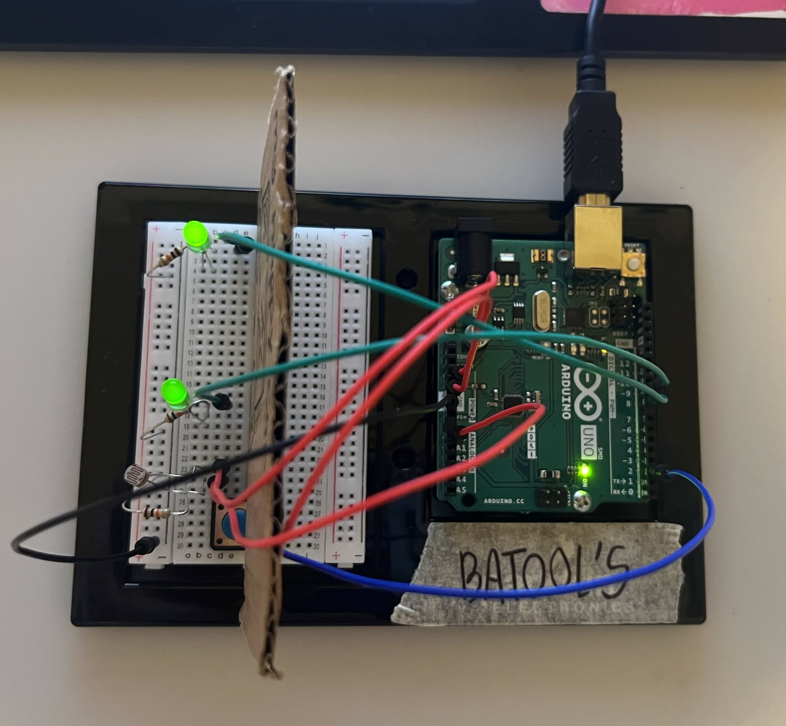
So I was thinking of how I could make something creative enough to pass this assignment vibes check so I thought of photocell ( which is digital) and a Tactile push button ( which is analog ) to light up my cute little car,
You know how it is when you’re driving in the dark – you need those headlights on, and when you want to change lanes, you’ve gotta give a signal. That’s exactly what I wanted to mimic.
So, when it gets dark, my little car’s headlights kick in with the help of two LEDs, and if I want to switch lanes, I just press that button, and the LEDs start blinking to signal my lane change. Cool, right.
Materials I used:
Arduino board (e.g., Arduino Uno)
2 LEDs (green)
2 x 220-ohm resistors (for current limiting)
Tactile push-button switch
Photocell (Light-dependent resistor, LDR)
10k-ohm resistor (for voltage divider)
Breadboard and jumper wires
Video:
Connectivity:
if its not THAT clear from the pic:
I connected a jumper wire from the ground (GND) rail on the breadboard to the GND (ground) pin on the Arduino.
I then connected a jumper wire from the 5V rail on the breadboard to the 5V pin on the Arduino.
I then connect another jumper wire from the 5V rail on the breadboard to the row where the side of the photocell connected to 5V is placed.
Finally I used a jumper wire to connect the other side of the photocell to the same row as the 10k-ohm resistor’s other end.
Code:
const int led1Pin = 8;           // Define a constant integer variable for the pin of the first LED.
const int led2Pin = 9;           // Define a constant integer variable for the pin of the second LED.
const int buttonPin = 2;         // Define a constant integer variable for the pin of the tactile button.
const int photocellPin = A0;     // Define a constant integer variable for the pin of the photocell sensor.

int led1State = LOW;              // Initialize an integer variable to store the state of the first LED as LOW.
int led2State = LOW;              // Initialize an integer variable to store the state of the second LED as LOW.
int buttonState = LOW;            // Initialize an integer variable to store the state of the tactile button as LOW.
int lastButtonState = LOW;        // Initialize an integer variable to store the previous state of the button as LOW.
int lightValue = 0;               // Initialize an integer variable to store the light reading from the photocell.
int threshold = 500;              // Set a threshold value for the light reading. You can adjust this value based on your environment.

void setup() {
  pinMode(led1Pin, OUTPUT);        // Set the pin of the first LED as an OUTPUT.
  pinMode(led2Pin, OUTPUT);        // Set the pin of the second LED as an OUTPUT.
  pinMode(buttonPin, INPUT_PULLUP); // Set the pin of the tactile button as an INPUT with internal pull-up resistor.
  pinMode(photocellPin, INPUT);    // Set the pin of the photocell sensor as an INPUT.
}

void loop() {
  lightValue = analogRead(photocellPin); // Read the analog value from the photocell sensor.

  // Check the photocell value to determine whether it's dark or light.
  if (lightValue < threshold) {
    // It's dark, turn both LEDs on.
    digitalWrite(led1Pin, HIGH); // Turn on the first LED.
    digitalWrite(led2Pin, HIGH); // Turn on the second LED.
  } else {
    // It's light, turn both LEDs off.
    digitalWrite(led1Pin, LOW);  // Turn off the first LED.
    digitalWrite(led2Pin, LOW);  // Turn off the second LED.
  }

  buttonState = digitalRead(buttonPin); // Read the state of the tactile button.

  if (buttonState != lastButtonState) {
    if (buttonState == LOW) {
      // Button pressed, toggle LED states based on previous states.
      if (led1State == LOW && led2State == LOW) {
        led1State = HIGH;
      } else if (led1State == HIGH && led2State == LOW) {
        led2State = HIGH;
        led1State = LOW;
      } else {
        led2State = LOW;
      }

      digitalWrite(led1Pin, led1State); // Set the state of the first LED.
      digitalWrite(led2Pin, led2State); // Set the state of the second LED.
    }
    delay(50); // Introduce a debounce delay to prevent rapid button presses.
  }
  lastButtonState = buttonState; // Store the current button state for comparison in the next loop iteration.
}
reflection:
This might not have been a supper Idea, However I faced a little creativity block this week that took me a hard time to set a side
Making Interactive Art: Set the Stage, Then Shut Up and Listen
I found this reading quite interesting. The natural instinct of wanting to help and make things easier for us sometimes makes us forget the fact that we might be oversharing or spoiling the experience. My takeaway from this reading would be the point Tigoe made about listening. Oftentimes in the excitement or nervousness of showing something to others, it’s easy to forget to actually see how they feel about it while interacting with it. When I’m showing my friends and family the weekly assignments from this class, I do expect their encouragement and feedback but I don’t think I fully listen or focus on their reactions, only because I’m so focused that the project is delivered exactly the way I want it to be. For my midterm project, I had an interactive Christmas tree designing component. I remember telling someone where exactly to place the lights because I had imagined it that way, forgetting that that’s for them to decide. I would definitely introspect more on this, shut up and listen after I’ve set the stage for people.
Physical Computing’s Greatest Hits (and misses)
I liked the idea of ‘meditation helpers’. While I know that it cannot fully capture the human state of mind and the machine may just be making educated guesses about how to do so by looking at heart and breath rates, the very intent of using physical computing for something like this to get you to a calmer and meditative state interests me. It left me thinking for a solid fifteen minutes on ways that we could actually make this work with more accuracy. This complements the purpose of the reading and the idea that even though themes may be recurring they allow a lot of room for originality. I also really appreciate having a blog for this class that lets us view and take inspiration from others’ works. Sometimes I feel like my ideas would be repetitive of the previously done ones but after this reading I fully agree that all pieces, even if they use the exact same materials, are completely different renditions and convey unique and individual thoughts.
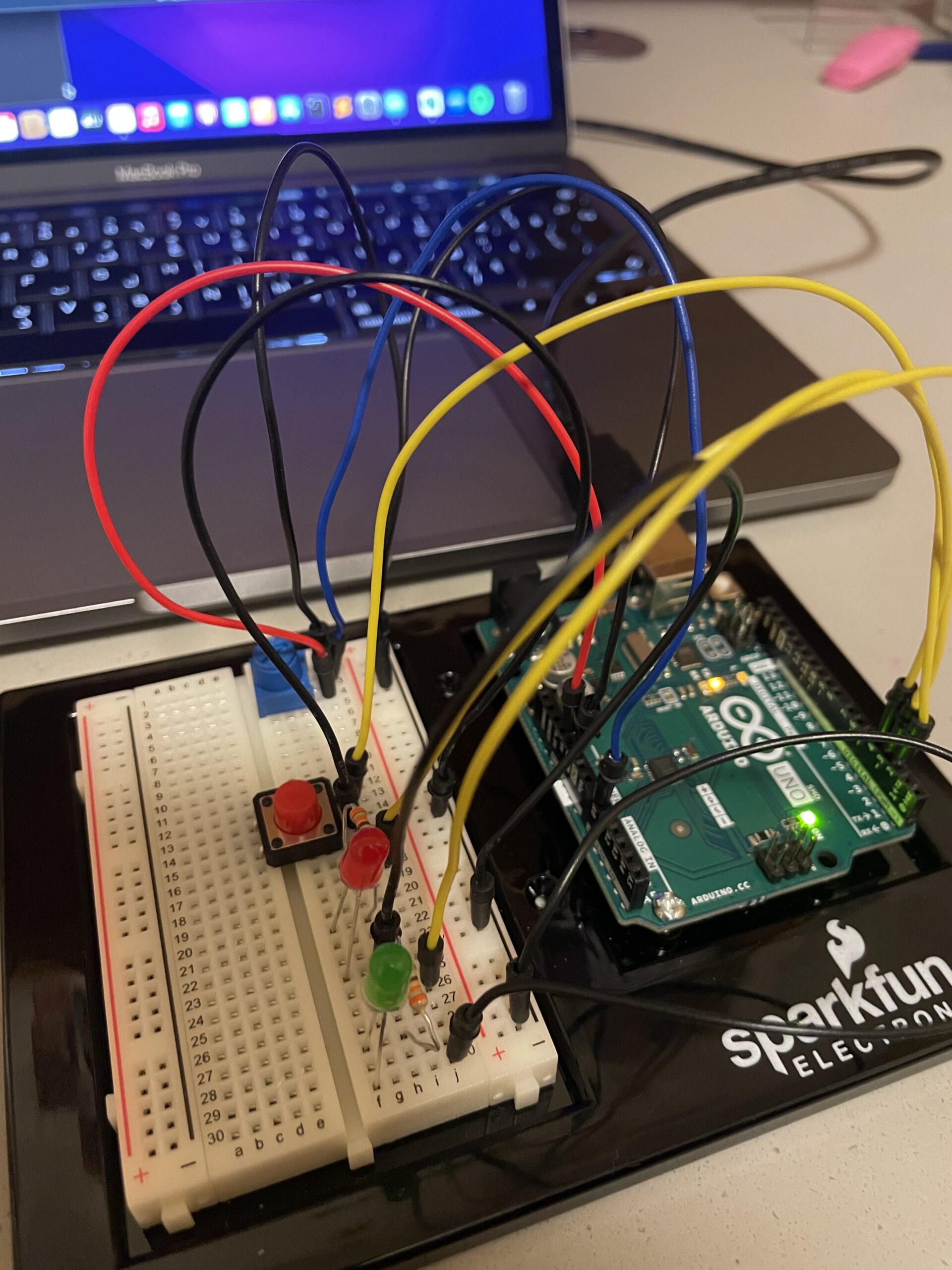
I created an alarm system that allows users to toggle the alarm on and off using a button. When activated, signified by the green LED, the alarm, represented by a red LED, responds to the surrounding light conditions. Specifically, the red LED turns on when the environment is well-lit and remains off in darkness.
How the Alarm Works
Alarm Setting:
– The user sets the alarm by pressing the blue button.
– The green LED, confirms whether the alarm is actively set (green LED on).
Light Sensing:
– Once the alarm is set, the system relies on a Light-Dependent Resistor (LDR) to detect ambient light levels.
Alarm Activation:
– In a well-lit environment, the red LED, representing the alarm, activates, turns on and off.
Alarm Deactivation:
– In darkness, the red LED remains turned off.
Components Used:
– LEDs: One red and one green
– Light-Dependent Resistor (LDR): Detects changes in ambient light conditions.
– Push-button Switch (Digital Sensor): Enables user interaction to set and unset the alarm.
Reflection
Working on this project I better understand the Arduino programming syntax, and analog input & output. Later when we learn to use sounds and music, I could include a sound for the alarm for better user experience.
The concept of this circuit is pretty straightforward, it’s a stopwatch! You specify the number of seconds you want the stopwatch to count by setting the potentiometer to a number on a scale of 1-60. Then you press on the red button. The LEDs start lighting in an alternating pattern that represents the seconds passed. When the time specified has passed both LEDs turn off.
Process & Highlights:
The potentiometer is connected in series with the analog input and is used to set the countdown time. The switch is connected in parallel and is used to start the countdown. The LEDs are connected in parallel with resistors and are used to display the countdown time. One LED indicates even seconds, and the other indicates odd seconds and it varies each time depending on the previous state.
Here is a video demo of the switch:
Code:
const int potentiometerPin = A0;
const int switchPin = 2;
const int ledPin1 = 3;
const int ledPin2 = 4;

int countdownTime = 0;
bool countdownStarted = false;

void setup() {
  pinMode(potentiometerPin, INPUT);
  pinMode(switchPin, INPUT_PULLUP);
  pinMode(ledPin1, OUTPUT);
  pinMode(ledPin2, OUTPUT);
  Serial.begin(9600);
}

void loop() {
  if (!countdownStarted) {
    countdownTime = map(analogRead(potentiometerPin), 0, 1023, 1, 60); // Set countdown time based on potentiometer
    Serial.println(countdownTime);
  }

  if (digitalRead(switchPin) == LOW) {
    countdownStarted = true;
  }

  if (countdownStarted && countdownTime > 0) {
    countdownTime--;
    displayCountdown();
    delay(1000); // One-second delay
  } else if (countdownTime == 0) {
    // Countdown finished
    digitalWrite(ledPin1, LOW);
    digitalWrite(ledPin2, LOW);
    countdownStarted = false;
  }
}

void displayCountdown() {
  int ledState = (countdownTime % 2 == 0) ? HIGH : LOW; // Toggle LED state
  digitalWrite(ledPin1, ledState);
  digitalWrite(ledPin2, !ledState);
}
Reflections:
I found this exercise a bit harder than the first one but it was fun to implement. If I could change one thing about my circuit, it would be to maybe have a screen display the seconds that have elapsed as well. I would love to create more advanced circuits in the future and find a way to incorporate more creativity within.
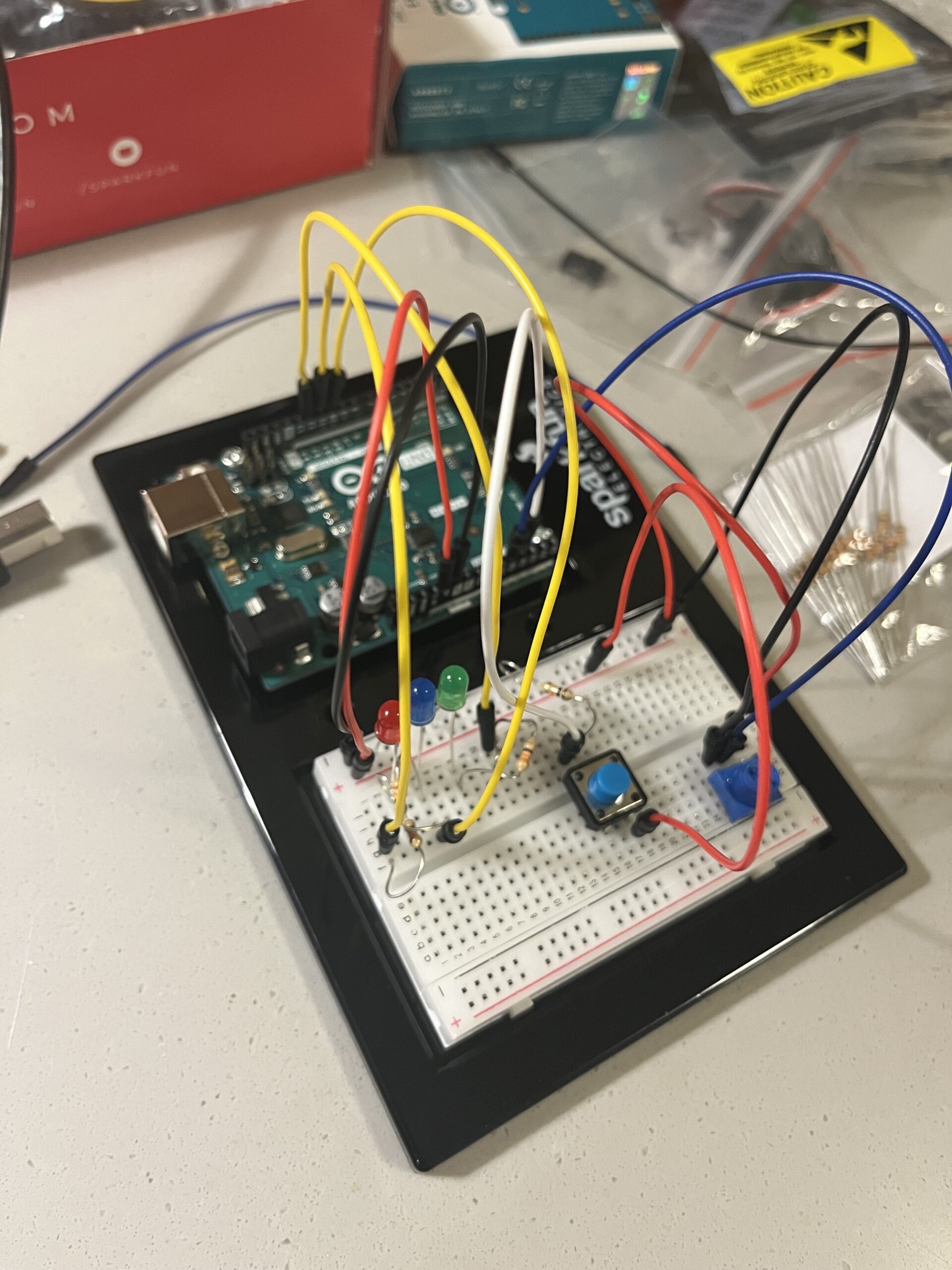
For this assignment, I decided to make a simple circuit using three LEDS, a switch and a potentiometer.
The idea is that it functions as a way to communicate three moods: anger, sadness and happiness. The mood is decided through the potentiometer, which maps the analog reading to a number within the range 0 – 90. If it’s in between 0-30, the green LED lights up, if it’s between 30 – 60, the blue LED lights up, and anything after 60 up till 90 makes the red LED light up. The LEDs blink in morse code – the red LED spells ANGRY, the blue LED spells SAD, and the green LED spells HAPPY. The digital switch in the circuit is used to turn the circuit on or off, with the LEDs only blinking if the switch is pressed.
code highlights:
const int greenLED = 12;
const int redLED = 11;
const int blueLED = 10;
const int btn = A2;
const int pot = A1;
int value;
int currLED = 0;

void flashDot() {
  digitalWrite(currLED, HIGH);
  delay(250);
  digitalWrite(currLED, LOW);
  delay(250);
}

void flashDash() {
  digitalWrite(currLED, HIGH);
  delay(1000);
  digitalWrite(currLED, LOW);
  delay(250);
}

void setup() {
  pinMode(redLED, OUTPUT);
  pinMode(greenLED, OUTPUT);
  pinMode(blueLED, OUTPUT);
  Serial.begin(9600);
}

void loop() {
  int btnState = digitalRead(btn);
  int potVal = analogRead(pot);
  value = map(potVal, 0, 1023, 0, 90);

  Serial.println(currLED);
  Serial.println(value);
  if (btnState == LOW) {
    digitalWrite(greenLED, LOW);
    digitalWrite(redLED, LOW);
    digitalWrite(blueLED, LOW);
    // currLED = 0;
  }
  if (value <= 30) {
    currLED = greenLED;
    //     digitalWrite(redLED, LOW);
    // digitalWrite(blueLED, LOW);
  } else if (value > 30 && value <= 60) {
    currLED = blueLED;
    //     digitalWrite(greenLED, LOW);
    // digitalWrite(redLED, LOW);
  } else {
    currLED = redLED;
    //         digitalWrite(greenLED, LOW);
    // digitalWrite(blueLED, LOW);
  }

  if (btnState == HIGH) {
    //   digitalWrite(greenLED, LOW);
    //   digitalWrite(redLED, LOW);
    //   digitalWrite(blueLED, LOW);
    // } else if (btnState == LOW) {
    if (currLED == greenLED) {
      digitalWrite(blueLED, LOW);
      digitalWrite(redLED, LOW);
      flashDot();  // H
      flashDot();
      flashDot();
      flashDot();
      delay(1000);  // Gap between letters

      flashDot();  // A
      flashDash();
      delay(1000);  // Gap between letters

      flashDot();  // P
      flashDash();
      flashDot();
      flashDot();
      delay(1000);  // Gap between letters

      flashDot();  // P
      flashDash();
      flashDot();
      flashDot();
      delay(1000);  // Gap between letters

      flashDash();  // Y
      flashDot();
      flashDash();
      flashDash();
      delay(1000);  // Gap between words
    } else if (currLED == blueLED) {
      digitalWrite(greenLED, LOW);
      digitalWrite(redLED, LOW);
      flashDot();  // S
      flashDot();
      flashDot();
      delay(1000);  // Gap between letters

      flashDot();  // A
      flashDash();
      delay(1000);  // Gap between letters

      flashDash();  // D
      flashDot();
      flashDot();
      delay(1000);  // Gap between words
    } else if (currLED == redLED) {
      digitalWrite(blueLED, LOW);
      digitalWrite(greenLED, LOW);
      flashDot();  // A
      flashDash();
      delay(1000);  // Gap between letters

      flashDash();  // N
      flashDot();
      delay(1000);  // Gap between letters

      flashDash();  // G
      flashDot();
      flashDot();
      delay(1000);  // Gap between letters

      flashDot();  // R
      flashDash();
      flashDot();
      delay(1000);  // Gap between letters

      flashDash();  // Y
      flashDash();
      delay(1000);  // Gap between words
    }
  }
}
The code is pretty simple and straightforward. One thing I like about my code is using the functions flashDash and flashDot, as it made it much easier to translate the morse code into blinking.
reflections:
One thing I struggled with and couldn’t really fix and/or understand why it was happening was the delayed transition between states, i.e. it takes a while to go from green to red etc., or even to turn off (as seen in the video). In the future, I’d want to be able to assess the root cause of this issue as it could be very problematic in other sorts of circuits where timing is very necessary.
I like the guidebook on commonly-made physical computing projects in class. I’ve thought about what it must be like to be a professor for an intro project-based class, like Intro to CS or Intro to IM, as there must be ideas that are constantly recycled each semester and the professor will have to pretend that they’re novel even when they’ve seen it a million times before. I assume a platformer game will always show up in Processing/P5.js class. Perhaps a paint/drawing program too, a particle system/ pattern animation, recreations of classic games like Pong or Snake. That’s not to say that they’re boring, as the reading also talks about how the cliches can sometimes be used as a base for something more interesting, but it’s fun to think about ideas that are strangely common.
Despite them being constantly recycled, it is possible to make interesting, unique projects out of them. I can think of a visual novel-esque game being one that is likely technically similar across most games of it’s genre, yet the deciding factor between a good and bad visual novel is the story being told, not the implementation of ‘click to see the next line of text’. Perhaps one of the best ways of being creative is to mix-up an existing overused form of media instead of trying to be both novel and interesting at the same time, as then you might be limited by your technical capabilities rather than your creative ones. In the case of the reading, video mirrors have been done. A Lot. Yet, this means that it is relatively easy to implement one thanks to the wealth of documentation and existing implementations on the internet, and you can focus instead on the ‘what’ you want to convey through your project, instead of the ‘how’.
The other reading compliments Don Norman’s chapters from the past few weeks really well. Show, don’t tell, in your projects. Students learn better when they make the intuition between two objects, rather than memorizing the two objects. Likewise, I assume that viewers of an art piece will enjoy it more when they come to their own conclusions about it, than being told what to feel. Of course, artists are always trying to convey something, and to have every viewer of their piece think wildly differently from their intent is probably not the artist’s intention. Through the design process itself, artists can guide viewers to their intent, to gently nudge them in the right direction without having to hold their hand. I like to think about Escape Rooms in this example. The goal of an Escape Room is to escape from it, yet players will find it unfun if the lock and key are both on the same table as they might feel it is too easy. Yet, if the puzzle is too difficult, players will feel frustrated and will not enjoy it either. The designers of Escape Rooms must strike a delicate balance between making a puzzle that is not easily solvable, yet guiding users delicately to their goal. For example, the usage of a padlock vs a combination lock will intuitively guide the players on what they should look for ( a key or a code ).
Concept
With what we currently know about Arduino, there were many things I am technically incapable of making yet, such as using the servo/motors or the LCD screen. Given the lax requirements for this week’s project of having 1 analog and 1 digital button, and 2 LEDs, I wasn’t sure what I could do with it what I currently have ( momentary switches, light detecting diodes ) while still being creative, so I thought of making a game of sorts and I came up with a memory game with the buttons.
Implementation
The light detecting diode ( analog ) is used to start/restart the game. When the LDR is covered and it becomes dark, the game is started. The momentary buttons are used to play the game.
Once the game is started, the LEDs will blink in sequence, and you have to replicate the sequence with the aptly-colored buttons to light up the same LEDs in the same order. There are multiple rounds, starting with 1 LED, all the way up to 8 LEDs. The sequence will blink again at the start of each round, with the addition of a new LED in the sequence. The player will have to rely on their memory to press the 8 LEDs in the right order.
The LEDs also double both as the game mechanism, and information mechanism. I use the LEDs to display game state information too. When the user has lost ( pressed an LED in the wrong order) , the LEDs will all blink twice before turning off. When the user has won, the LEDs will blink in a fun pattern on repeat until a new game is started.
Video demo : In the first attempt, I made a mistake and the ‘loss sequence’ plays. The second attempt, I complete the challenge and the ‘victory sequence’ plays.
Expansion
It would be fun to use other forms of inputs other than buttons for this game! I was thinking of using the ultrasonic detector as a challenge too, e.g player has to remember the distance they have to trigger the ultrasonic detector. Perhaps once I learn about more sensors and inputs, I could think about implementing them into this game so there’s more variety rather than just a sequence of LEDs.