
Concept
For this week’s assignment, I decided to show the common problem of pedestrians when crossing the road. My idea was to create a pedestrian crossing light, which would show the common problem of having “infinite” red light and only limited actual crossing green light. I believe this is a common problem in any country and anyone can relate to the idea of this project.
Video: Pedestrian Traffic Light
Diagram, Code, Highlights, and Challenges of the Project
To make this project, I decided to break it into three steps.
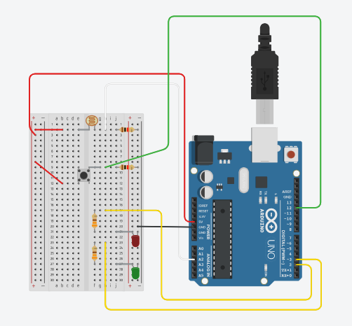
Firstly, I made a switch as a push button, which will turn on the green LED. For this, I built a circuit for the switch button, which I learned from the class material. I am proud of this step, as I could apply the previous knowledge (building the circuit of the light sensor) and understand how to do the same with the switch button. I used a 10K Ω resistor, a green push button (to indicate the same color as the LED color), a green wire that connects to pin 12, a red wire that connects to 5V, and a black wire for the GND connection. One challenge I faced was forgetting that the current could not jump from one place on the breadboard to another, so I added another red wire to finish the connection.
Moreover, I made a simple circuit for the green and red light, using green and red LEDs, 2 330Ω resistors, and yellow wires connected to pins 2 and 3. I didn’t have to use an additional black wire, as I intentionally had all of my components connected in a way that uses only 1 black wire connected to GND.
As I completed building this, I wrote a simple program that will turn on the green LED, and turn off the red LED, when the green button is pushed. Moreover, I made a code for the green LED blinking. For this part of the project, I used a digital sensor and controlled it in a digital fashion.
Lastly, I decided to add an analog sensor – a light sensor – which will control the brightness of the red LED. I had no problem building this part of the circuit, however, I had to decide whether I wanted to completely turn off the red LED or control the red LED in a fashion that is independent of the digital switch. If I decided to turn off the LED using a light sensor, I would need to think about 4 different options of its connection to the switch button: switch on & sensor value >400, switch on & sensor value <400, switch off & sensor value >400, switch off & sensor value <400. I decided that independent control of the light sensor would reflect my concept better. Therefore, I made a red LED to always have a dimmed brightness, and when the light sensor is covered the LED will become brighter.
Here, is the code for my program:
// assigning variables to the pins
// push button has a connection to pin 12
// green LED has a connection to pin 2
// red LED has a connection to pin 3

int pushButton = 12;
int greenLED = 2;
int redLED = 3;

// the setup routine
void setup() {
  // initialize serial communication at 9600 bits per second:
  Serial.begin(9600);
  // make the pushbutton's pin an input
  pinMode(pushButton, INPUT);
  // make green LED and red LED pins as output
  pinMode(greenLED, OUTPUT);
  pinMode(redLED, OUTPUT);
}

// the loop routine runs over and over again forever:
void loop() {

  // read the input pin of the push button:
  int buttonState = digitalRead(pushButton);
  // print out the state of the button:
  Serial.println(buttonState);
  delay(1);  // delay in between reads for stability

  // if statement for controlling the red and green LEDs through the push button (digital switch)
  // if button is pushed
  // turn off the red LED and blink the green LED with a delay in between the blinks

  if (buttonState == HIGH) {

    digitalWrite(redLED, LOW);

    digitalWrite(greenLED, HIGH);
    delay(1000);
    digitalWrite(greenLED, LOW);
    delay(1000);

    // if button is not pushed
    // green LED is always off
    // red LED is always on
    // and the red LED is controlled by the light sensor values a.k.a. the brightness
    // if the sensor value is less than or equals to 400, the brightness of the red LED is at maximum
    // if the sensor value is more than 400, the brightness of the red LED is alway dimmed at brighness of 10

  } else {
    //if the green button is not pushed,
    // the green LED is not turning on
    digitalWrite(greenLED, LOW);

    // initializing variable called sensorValue which reads the values from A2 analog pin
    int sensorValue = analogRead(A2);

    if (sensorValue <= 400) {
      analogWrite(redLED, 255);
    } else {
      analogWrite(redLED, 10);
    }
  }
}
Future Work and Reflection
Overall, I believe that I achieved all of my goals for this project. I was able to practice the knowledge I gained during class work and apply it in a new context. I am proud of the work I have done. Although I faced several challenges, which I described above, I was able to resolve them easily. For the next work, I am planning to keep up with my method of breaking the big project into smaller parts and achieving the same good results.