Assignment 8: Serial Communication – In Class Exercises

Exercise 1: Control p5js through Arduino

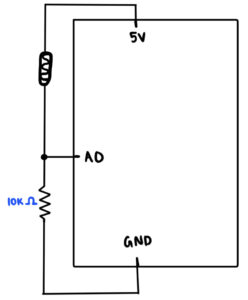
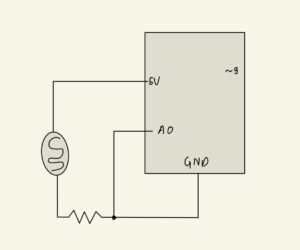
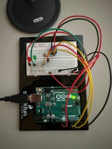
In this exercise, we had to have an analog sensor on our Arduino and let those values control something in p5js. Hence, I used a photo resistor and the values from that would make an ellipse in p5js move along its horizontal axis.

Schematic:

p5js Code:
//Class Exercise 1: Controlling P5JS objects from Arduino
let xValue = 0;  

function setup() {
  createCanvas(700, 700);
}

function draw() {
  background(220);
  
  if (!serialActive) {
    text("Press Space Bar to select Serial Port", 20, 30);
  } 
  
  else {
    text("Connected", 20, 30);
    ellipse(xValue, height/2, 150, 150);
  }
}

//Sets up the serial connection
function keyPressed() {
  if (key == " ") {
    setUpSerial();
  }
}

//Function to read in serial data from the Serial Port. 
function readSerial(data) {
  if (data != null) {
    //Mapping the sensor values from 'data' - 0 to 500 - 0
    xValue = map(data, 0, 1023, 0, width);
  }
}

Arduino Code:
const int lightSensor = A0;

void setup() {
  Serial.begin(9600);
  pinMode(lightSensor, INPUT);
}

void loop() {
  //Reads value from the sensor and prints it to the Serial Port (p5js)
  int lightValue = analogRead(lightSensor);
  Serial.println(lightValue);
}
Video:

Exercise 2: Control Arduino LEDs through p5js

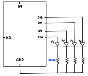
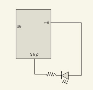
In this exercise, we had to simply control LEDs on our Arduino board via p5js code. Hence, I decided to do something where depending on where the user’s mouse is on the canvas on p5js, it will light up a specific LED. So, for instance, if it’s on the far left side, it will switch on the left most LED, and if it’s on the right side, it will switch on the right most LED and so on.

Schematic:

p5js Code:
let circle_size = 50;

//These are variables to determine whether the any of the coloured lights are ON or OFF
let g_ON = 0;
let b_ON = 0;
let r_ON = 0;
let y_ON = 0;

function setup() {
  createCanvas(700, 700);
}

function draw() {
  background(0);
  fill(255);
  textAlign(CENTER);
  textSize(20);
  text("Move the cursor around to switch the LED's ON!", width/2, 40);
  
  if (!serialActive) {text("Press Space Bar to select Serial Port", width/2, 75); } 
  else {text("Connected", width/2, 75); }
  
  //Depending on which side of the canvas the mouse is on, that specific LED will switch on and the circle icon will also be switched to that color as well
  if(mouseX < width/4) {
    fill("red");
    r_ON = 1;
    y_ON = 0;
    b_ON = 0;
    g_ON = 0;
  }
  
  else if(mouseX >= width/4 && mouseX < width/2) {
    fill("yellow");
    r_ON = 0;
    y_ON = 1;
    b_ON = 0;
    g_ON = 0;
  }
  
  else if(mouseX >= width/2 && mouseX < 3*width/4) {
    fill("blue");
    r_ON = 0;
    y_ON = 0;
    b_ON = 1;
    g_ON = 0;
  }
  
  else {
    fill("green");
    r_ON = 0;
    y_ON = 0;
    b_ON = 0;
    g_ON = 1;
  }
  
  circle(mouseX, mouseY, circle_size);
}

function keyPressed() {
  if(key == " ") {
    setUpSerial();
  }
}

function readSerial(data) {
  if(data != null) {
    //Sends the light ON/OFF messages for all the lights to the arduino
    let sendToArduino = r_ON + "," + y_ON + "," + b_ON + "," + g_ON + "\n";
    writeSerial(sendToArduino);
  }
}
Arduino:
const int red_pin = 13;
const int yellow_pin = 11;
const int blue_pin = 4;
const int green_pin = 2;

void setup() {
  Serial.begin(9600);
  pinMode(red_pin, OUTPUT);
  pinMode(yellow_pin, OUTPUT);
  pinMode(blue_pin, OUTPUT);
  pinMode(green_pin, OUTPUT);

  // Blink them so we can check the wiring
  digitalWrite(red_pin, HIGH);
  digitalWrite(yellow_pin, HIGH);
  digitalWrite(blue_pin, HIGH);
  digitalWrite(green_pin, HIGH);
  delay(200);
  digitalWrite(red_pin, LOW);
  digitalWrite(yellow_pin, LOW);
  digitalWrite(blue_pin, LOW);
  digitalWrite(green_pin, LOW);

  //Checks while the Serial Port is available then we send '0'
  while(Serial.available() <= 0) {
    Serial.println("0");
    delay(300);
  }
}

void loop() {
  while(Serial.available()) {
    //We parse the integer values (ON/OFF) to the respective leds
    int red = Serial.parseInt();
    int yellow = Serial.parseInt();
    int blue = Serial.parseInt();
    int green = Serial.parseInt();

    //Once it's read the \n character, then we switch the according LEDs on
    if (Serial.read() == '\n') {
      digitalWrite(red_pin, red);
      digitalWrite(yellow_pin, yellow);
      digitalWrite(blue_pin, blue);
      digitalWrite(green_pin, green);
    }
    Serial.println(); //Needs two way handshake commuincation between ports. 
  }
}
Video:

Exercise 3: Two-way communication between p5js and Arduino

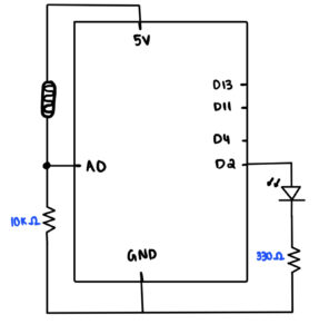
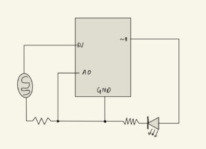
In this exercise, we were given a p5js code which drew a bouncing ball and it could change directions depending on some ‘wind’ variable. We were supposed to relay the information of when the ball bounced (hit the floor), then the LED would switch on, otherwise it’s off. Similarly, we would also be able to control the wind value through an analog sensor, hence I chose the photo resistor.

Schematic:

p5js Code:
let velocity;
let gravity;
let position;
let acceleration;
let wind;
let drag = 0.99;
let mass = 50;

//These are the variables which would be read and written from/to the Arduino
let sensor_wind = 0;
let led_ON = 0;

function setup() {
  createCanvas(640, 640);
  position = createVector(width/2, 0);
  velocity = createVector(0,0);
  acceleration = createVector(0,0);
  gravity = createVector(0, 0.5*mass);
  wind = createVector(0,0);
}

function draw() {
  background(255);
  
  if (!serialActive) {text("Press Space Bar to select Serial Port", 20, 30); } 
  else {text("Connected!", 20, 30); }
  
  fill(0);
  applyForce(wind);
  applyForce(gravity);
  velocity.add(acceleration);
  velocity.mult(drag);
  position.add(velocity);
  acceleration.mult(0);
  ellipse(position.x,position.y,mass,mass);
  
  if (position.y > height-mass/2) {
      velocity.y *= -0.9;  // A little dampening when hitting the bottom
      position.y = height-mass/2;
      led_ON = 1;  //If the ball makes contact with the ground, the LED will be ON
  }
  else {led_ON = 0;}   //Else the LED will be OFF
  
  //If the sensor_wind value from the Arduino that was mapped is greater than 0, then it will move the ball to the right
  if(sensor_wind > 0) {
    wind.x = 1;
  }
  
  //Else if the sensor_wind value from the Arduino is less than 0, it will move the ball to the left
  else if(sensor_wind < 0) {
    wind.x = -1;
  }
  
  //If it's 0, aka no wind, then it will just keep the ball where it is, no wind. 
  else {
    wind.x = 0;
  }
}

function applyForce(force){
  // Newton's 2nd law: F = M * A
  // or A = F / M
  let f = p5.Vector.div(force, mass);
  acceleration.add(f);
}

function keyPressed(){
  if (key == "m"){
    mass=random(15,80);
    position.y=-mass;
    velocity.mult(0);
  }
  
  if(key == " ") {
    setUpSerial();
  }
}

function readSerial(data) {
  if(data != null) {
    //Sends the LED ON/OFF information to the Arduino
    let sendToArduino = led_ON + "\n";
    writeSerial(sendToArduino);
    //Reads the sensor_wind values from the Arduino and maps its value to either -1 or 1 to correspond to wind direction. 
    sensor_wind = map(data, 0, 1023, -1 , 1);
  }
}
Arduino Code:
const int led_pin = 13;
const int lightSensor = A0;

void setup() {
  Serial.begin(9600);
  pinMode(led_pin, OUTPUT);
  pinMode(lightSensor, INPUT);

  //Check wiring: 
  digitalWrite(led_pin, HIGH);
  delay(200);
  digitalWrite(led_pin, LOW);

  while(Serial.available() <= 0) {
    Serial.println("0");
  }

}

void loop() {
  while(Serial.available()) {
    //Gets the led ON/OFF information from p5js and switches the led on/off accordingly
    int led_ON = Serial.parseInt();
    digitalWrite(led_pin, led_ON);

    //Gets the light value from the sensor and sends it to p5js
    int lightValue = analogRead(lightSensor);
    Serial.println(lightValue);
  }
}
Video:

Final Project Proposal – Yerkebulan Imanbayev

Concept

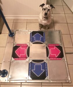
For my finally project, I was inspired by a classic Japanese video game called “Dance Revolution.” In this game, the user hears a song and has to tap on the right tiles of the platform that is under them in order to win the game: the tiles on which the person has to tap on appear faster and the game becomes harder over time. However, to put my own spin on the project, I decided to reverse the idea, and create “Dance Evolution.” In this game, the user will not be given a prior song but rather a set of tiles that they have to press on, similar to the original, and construct the song themselves.

picture taken from https://www.reddit.com/r/DanceDanceRevolution/comments/85guhf/my_self_made_ddr_pad_gallery_and_howto_in_comments/

The tiles will be modeled after the iconic “Dance Revolution” tiles.

Implementation:

The user will construct the song with the help of a set of successive arrows that they have to tap on, which in turn represent a certain instrument. After tapping, these instruments will be layered and will start turning into an actual song. The trick is that the user has to tap on the arrows/tiles in a timely manner, as the time slot for a successful tap will shrink over time. The user wins if they are able to tap on all tiles correctly and create the song that consists of all instruments: the beat, the bass, the chords, the melody, the pad, etc. The user loses if they do not tap on the tile on time, thereby ruining the structure of the song.

The instruments will most likely be generated using p5.js, in order to add an element of randomness and unpredictability so that the melodies and the beats heard in one round of the game will be different in another round. The user will also have the possibility of changing the key of the song by using a distance sensor, allowing them to hear the song in different renditions of their own volition.

Final Project Idea – Collision and Edge Detection Robot with Arduino and p5.js

Concept

The aim of this project is to create a robot that can avoid collisions and sudden edges while moving around. The robot will be controlled using an Arduino board and p5.js, a JavaScript library for creative coding. The robot will be equipped with an ultrasonic distance sensor and an infrared sensor to detect collisions and edges respectively. The robot will have two different modes of operation which can be controlled using serial communication between the Arduino and p5.js. One mode will allow the robot to roam freely, while the other mode will allow the user to control the robot using keys on the computer. The movement of the robot will be mapped onto the p5.js canvas.

Implementation

One of the Arduino boards will be connected to the computer which receives serial information from p5 and transmits them over to the other Arduino board. This is a two way link communication between the robot and the computer. The ultrasonic distance sensor will be connected to the servo motor, which will rotate the sensor to scan the environment. The infrared sensor will be attached to the front of the robot chassis to detect edges. The robot moves around using regular motors and wheels. Whenever an edge is detected or the distance sensor senses a possible collision, it starts moving backward in order to avoid imminent danger. It also transmits back the movement data that is later displayed in the form of a path in the p5 canvas.

Week 11: Final Project Proposal

Concept

For the final project I wanted to do something with drawings and LEDs. So I went with the simple idea of transferring a drawing in p5Js to outputs in LED patterns. I will play around with what other features I could add such as adding colour, brightness (using the alpha in p5Js), gradients, and more.

The project is aimed at entertaining the user, through lightings and real-time feedback as they explore the potential of controlling LEDs through drawing something on the screen.

Implementation

For the user input of the drawings, I will use p5Js and prompt the user to draw something onto the canvas, providing them with colour options. I am also exploring the idea of taking a real-time picture of them and showing their silhouettes through the LED patterns.

As for the physical LED pattern, I will be using Arduino to map the pixels onto their corresponding LED. It will not be a one-to-one mapping as it would take an absurd amount of LEDs otherwise. For the latter idea of a real-time picture, I am planning on roughly mapping their outlines onto the LED.

Final Project Preliminary Concept – Togyzkumalak

CONCEPT

For our final project, I want to create a version of the Kazakh traditional board game, Togyzkumalak (transl. “nine pebbles”). The game is played on a board consisting of two rows of nine pits each, with 2 larger pits (storehouses) between the two rows. The objective of the game is to capture more pebbles than the opponent (-> high score). This is a two-player game.

game setup for reference

Each player will be using three buttons connected through Arduino to p5 to control their movements in the game (left, right, enter). On p5 will be the visualization of the board. Players will use buttons to choose which pit to take the pebbles from.

The rules of the game are (with consideration of Arduino):

1) The game begins with 9 pebbles in each pit. Each player will be given 1 minute to make a move.

2) The first player chooses one of the 9 pits on their side using the “left”, “right”, and “enter” buttons on their Arduino.

3) All of the pebbles from the chosen pit are distributed evenly over the pits in an anti-clockwise direction.

        • If there is more than 1 pebble in the pit, the first pebble is put back into the pit it was taken from.
        • If there is only 1 pebble in the pit, the first pebble is moved to the next pit in the anti-clockwise direction.
anti-clockwise movement of the pebbles

4) If the last pebble to be moved is put into one of the opponent’s pits and the total of the pebbles in that pit is an even number, they get moved to the player’s storehouse and add to their total score.

moving pebbles from the opponent’s pit if the total in the said pit is an even number

5) opponent’s pit can be “conquered”, meaning that all the pebbles that ever fall on that pit will move to the player’s storehouse. However, there are some more conditions that need to be followed to do that (it will be checked by p5 automatically):

        • the total of the pebbles in the last pit you’ve visited must be 3;
        • the pit shouldn’t be the rightmost pit of the player (pit #9);
        • you must not already have a “conquered” pit;
        • if your opponent already has “conquered” a pit on your side, you can’t “conquer” a pit that is opposite to it;

6) If one of the players doesn’t have any more pebbles in any of their 9 pits, the opponent’s pits are emptied into their storehouse.

7) The one with the biggest score wins.

CREATIVITY

To add something new to the game, chance games will be played between the turns:

        • after every 3rd turn, a player will be given a chance to roll a die in the game. The die will have both negative ((-3) to (-1)) and positive numbers (1 to 3). The number shown will be added to the score of the player.
        • after every 7th turn, a player will be given a choice between three cards shown backward. One of the cards will be empty, one will have a challenge, and the last one will have a bonus. Drawing an empty card will safely return you to the game. Drawing a challenge card will make decrease your turn time to 30s for the next two turns. Drawing a bonus card will add 1 more minute to your turn time for the next two turns.

POSSIBLE CHALLENGES

I think I will have a difficult time implementing the game logic. Another thing I usually have issues with is checking the time (setting up a timer). I also need to think of the way the transitions between different states of the game to make it look animated and not mechanical.

Week 11 – in class exercises – Sarthak and Yerk

Exercise 1

Scheme: 

Code:

let xVal = 0; //initializing the X value for the position 

function setup() {
  createCanvas(640, 480);
}

function draw() {
  background(230);
  if (!serialActive) {
    text("Press Space Bar to select Serial Port", 20, 30);
  } else {
    // draw an ellipse
    ellipse(xVal, height/2, 100, 50); //giving the ellipse the value of the x position initialized above

  }
}

function keyPressed() {
  if (key == " ") {
    // important to have in order to start the serial connection!!
    setUpSerial();
  }
}

function readSerial(data) {
  if (data != null) {
    xVal = map(data, 0, 500, 0, width); //mapping the values received from the photosensor to control the X position of the ellipse 
    console.log(data);
  }
}
const int pSensor = A0;

void setup() {
  pinMode(pSensor, INPUT);
  Serial.begin(9600);
}

void loop() {
  int val = analogRead(pSensor); //initializing the value received from the sensor 
  Serial.println(val); //sending the value of the sensor to p5js
}

Video:


Exercise 2

Scheme: 

Code:

//p5js code

let change = 0; //initializing the variable for the distance between two consecutive center points of the rectangle
let previousX; //initializing the variable for the X dimension of the previous position of the rectangle 
let previousY; //initializing the variable for the Y dimension of the previous position of the rectangle 

function setup() {
  createCanvas(640, 480);
  textSize(18);
  textAlign(CENTER);
  previousX = 0;
  previousY = 0;
}

function draw() {
  background('red');

  if (!serialActive) {
    fill('white');
    text("Press Space Bar to select Serial Port", width/2, height/2);
  } else {
    fill('white');
    rectMode(CENTER);
    rect(mouseX, mouseY, 200,200); //controlling the center of the rectangle with the mouse 
    fill('black');
    text("Move as fast as you can to control the brightness of the LED", width/2,20);
    getChange(); //calling the function that will track the distance between the two consecutive positions of the rectangle 
  }
  
}

//calculating the distance of two consecutive rectangle positions 
function getChange(){ 
  change = floor(sqrt(pow((mouseX - previousX),2) + pow((mouseY - previousY),2)));
  previousX = mouseX;
  previousY = mouseY;
}

function keyPressed() {
  if (key == " ") {
    setUpSerial();
  }
}

function readSerial(data) {
  if (data != null) {
    console.log(change);
    writeSerial(change); //sending the value of the distance two control the LED brightness 
  }
}
const int led = 9;

void setup() {
  // put your setup code here, to run once:
  pinMode(led, OUTPUT);
  Serial.begin(9600);

  while (Serial.available() <= 0) {
    Serial.println("0");
    delay(300);
  }
}

void loop() {
  while (Serial.available()) {
    int brightness = Serial.parseInt(); // read the incoming data as an integer
    analogWrite(led, brightness); // set the LED brightness based on incoming data
    Serial.println();
  }
}

Video:

Exercise 3

Scheme: 

Code:

//p5js code

let velocity;
let gravity;
let position;
let acceleration;
let wind;
let drag = 0.99;
let mass = 50;

let ard_wind = 1; //initializing the wind speed 
let bit;

function setup() {
  createCanvas(640, 360);
  position = createVector(width / 2, 0);
  velocity = createVector(0, 0);
  acceleration = createVector(0, 0);
  gravity = createVector(0, 0.5 * mass);
  wind = createVector(0, 0);
  bit = 0; //initializing the value for the LED
}

function draw() {
  background(255);

  if (!serialActive) {
    text("Press Space Bar to select Serial Port", 20, 30);
  } else {
    applyForce(wind);
    applyForce(gravity);
    velocity.add(acceleration);
    velocity.mult(drag);
    position.add(velocity);
    acceleration.mult(0);
    ellipse(position.x, position.y, mass, mass);

    if (position.y > height - mass / 2) {
      velocity.y *= -0.9; // A little dampening when hitting the bottom
      position.y = height - mass / 2; 
      bit = 1; //lighting up the LED upon collision with "the ground"
    } else {
      bit = 0; //turning off the LED when the ball is not touching "ground"
    }
  }
}

function applyForce(force) {
  // Newton's 2nd law: F = M * A
  // or A = F / M
  let f = p5.Vector.div(force, mass);
  acceleration.add(f);
}

function keyPressed() {
  if (keyCode == LEFT_ARROW) {
    wind.x = ard_wind * -1; //when left arrow is pressed, the velocity of the wind attains a negative value and the ball moves to the left 
  }
  if (keyCode == RIGHT_ARROW) {
    wind.x = ard_wind; //when the right arrow is pressed, the velocity of the wind attains a positive value and the ball moves to the right 
  }
  if (keyCode == DOWN_ARROW) {
    mass = random(15, 80);
    position.y = -mass;
    velocity.mult(0);
  }
  if (key == " ") {
    // important to have in order to start the serial connection!!
    setUpSerial();
  }
}

function readSerial(data) {
  if (data != null) {
    let sen = bit + "\n";
    writeSerial(sen); //sending the values to light up or turn off the LED
        
    ard_wind = map(data, 0, 300, 0, 10); // mapping the data received from arduino to a sensible range for the wind velocity 
    console.log(ard_wind);    
  }
}
const int led = 12;
const int photoSensor = A0;

void setup() {
  // put your setup code here, to run once:
  Serial.begin(9600);
  pinMode(led, OUTPUT);
  pinMode(photoSensor, INPUT);

  while (Serial.available() <= 0) {
    Serial.println(0);
    // delay(300);
  }
}

void loop() {
  while (Serial.available() > 0) {
    int bit = Serial.parseInt(); // read the incoming data as an integer
    digitalWrite(led, bit); // set the LED brightness based on incoming data

 //send the values of the photosensor to p5js
    int val = analogRead(photoSensor); 
    Serial.println(val);
  }
}

Video:


Week 11 – Seiral Communication

For the 11th Week assignment, we were tasked to pair up in groups of 2-3, and complete the following 3 exercises to fully understand the connection and communication methodologies between Arduino and p5Js. The 3 exercises were:

      1. make something that uses only one sensor  on arduino and makes the ellipse in p5 move on the horizontal axis, in the middle of the screen, and nothing on arduino is controlled by p5
      2. make something that controls the LED brightness from p5
      3. take the gravity wind example (https://editor.p5js.org/aaronsherwood/sketches/I7iQrNCul) and make it so every time the ball bounces one led lights up and then turns off, and you can control the wind from one analog sensor

The requirements were to post the code for each exercise, and the video of the LED lighting up with the ball bouncing.

We paired up in a group of 3, consisting of Abraiz Azhar, Ishmal Khalid, and Zunair Viqar. In the next few sections, we have described the solutions to each of the above exercises.

Prompt 1

Make something that uses only one sensor on arduino and makes the ellipse in p5 move on the horizontal axis, in the middle of the screen, and nothing on arduino is controlled by p5

Implementation

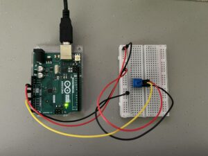
For this part, I made use of a potentiometer and connected it to the Arduino’s A0 port. The variable rVal changes according to the position of the potentiometer and this variable is in turn mapped to the ellipse’s x-position. I made the ellipse’s grey-scale value change according to the potentiometer’s reading.

Code
let rVal = 0;

function setup() {
  createCanvas(640, 480);
  textSize(18);
}

function draw() {
  // one value from Arduino controls the background's red color
  background(map(rVal, 0, 1023, 0, 255), 255, 255);

  if (!serialActive) {
    text("Press Space Bar to select Serial Port", 20, 30);
  } else {
    text("Connected", 20, 30);
    

    // Print the current values
    text('rVal = ' + str(rVal), 20, 50);
    text('alpha = ' + str(alpha), 20, 70);

  }
  
  // making an ellipse that moves according to the potentiometer's rVal 
  noStroke()
  fill(map(rVal, 0, 1023, 0, 255));
  ellipse(map(rVal, 0, 1023, 20, width - 20), height/2, 20);
}
Circuit


Prompt 2

Implementation & Challenges

The prompt for the second task seemed straightforward initially: create a system to control LED brightness using p5. However, it turned out to be more challenging than expected. Our initial approach was to map the mouseX position relative to the screen width to adjust the brightness of the lamp accordingly. We removed the code for reading from p5 and writing to Arduino, as we thought only sending data from p5 was needed. However, we later realized that both read and write operations are necessary for establishing a connection.

Despite this realization, we still encountered issues as we didn’t initially understand that data must be continuously read and written from both Arduino and p5 for the circuit to function properly. It wasn’t just limited to the handshake phase, but required continuous data exchange. Despite the challenges, this exercise provided us with a deeper understanding of the serial connection between p5 and Arduino.

We also faced challenges with data formatting during the data exchange. It was important to ensure that the data sent from p5 was properly formatted with the addition of ‘\n’, and that Arduino used println instead of print to receive the data. This was crucial for establishing reliable communication between p5 and Arduino, and it required careful attention to detail to get the formatting right.

Code
p5Js
let rVal = 0;
let alpha = 255;
let left = 0;
let right = 0;
let brightness = 0;

function setup() {
  createCanvas(640, 480);
  textSize(18);
}

function draw() {
  // one value from Arduino controls the background's red color
  background(map(rVal, 0, 1023, 0, 255), 255, 255);

  // the other value controls the text's transparency value
  brightness = map(mouseX, 0, 640, 0, 255);

  if (!serialActive) {
    text("Press Space Bar to select Serial Port", 20, 30);
  } else {
    text("Connected", 20, 30);
    

    // Print the current values
    text('rVal = ' + str(rVal), 20, 50);
    text('alpha = ' + str(alpha), 20, 70);

  }

}

function keyPressed() {
  if (key == " ") {
    // important to have in order to start the serial connection!!
    setUpSerial();
  }
}


function readSerial(data) {
  ////////////////////////////////////
  //READ FROM ARDUINO HERE
  ////////////////////////////////////

  if (data != null) {

    //////////////////////////////////
    //SEND TO ARDUINO HERE (handshake)
    //////////////////////////////////
    let sendToArduino = brightness + "\n";
    writeSerial(sendToArduino);
  }
}
Arduino .ino
int leftLedPin = 2;
int rightLedPin = 5;

void setup() {
  // Start serial communication so we can send data
  // over the USB connection to our p5js sketch
  Serial.begin(9600);

  // We'll use the builtin LED as a status output.
  // We can't use the serial monitor since the serial connection is
  // used to communicate to p5js and only one application on the computer
  // can use a serial port at once.
  pinMode(LED_BUILTIN, OUTPUT);

  // Outputs on these pins
  pinMode(leftLedPin, OUTPUT);
  pinMode(rightLedPin, OUTPUT);

  // Blink them so we can check the wiring
  digitalWrite(leftLedPin, HIGH);
  digitalWrite(rightLedPin, HIGH);
  delay(200);
  digitalWrite(leftLedPin, LOW);
  digitalWrite(rightLedPin, LOW);

  // start the handshake
  while (Serial.available() <= 0) {
    digitalWrite(LED_BUILTIN, HIGH); // on/blink while waiting for serial data
    Serial.println("0"); // send a starting message
    delay(300);            // wait 1/3 second
    digitalWrite(LED_BUILTIN, LOW);
    delay(50);
  }
}

void loop() {
  // wait for data from p5 before doing something
  while (Serial.available()) {
    digitalWrite(LED_BUILTIN, HIGH); // led on while receiving data

    int right = Serial.parseInt();
    if (Serial.read() == '\n') {
      analogWrite(rightLedPin, right);
      int sensor = analogRead(A0);
      Serial.println(sensor);
    }
  }
  digitalWrite(LED_BUILTIN, LOW);
}

Prompt 3

Implementation & Challenges

For the very last prompt, we were required to take an input from Arduino in the form of an Analog Sensor and also send data to Arduino to blink an LED.

Using an existing p5Js Sketch (https://editor.p5js.org/aaronsherwood/sketches/I7iQrNCul), the requirement was to blink the LED when the ball bounces, and use an Analog Sensor to control the wind.

Therefore, making use of the circuit we designed in class by taking help from the basics of these 3 sources, we began to adapt the Gravity Wind Example from p5Js:

      • Circuit (https://github.com/mangtronix/IntroductionToInteractiveMedia/blob/master/code/Week_11_Serial_schematic.png)
      • Arduino Code (https://github.com/mangtronix/IntroductionToInteractiveMedia/blob/master/code/Week11Serial.ino)
      • P5Js Starter Code (https://editor.p5js.org/mangtronix/sketches/s67XC0zT4)

The first task was to detect a bounce, and once a bounce was detected, we just simply sent a signal of ‘1’ to the Arduino – which only meant switching on the light, which would then switch off with ‘0’ being sent when the ball was in motion.

Similarly, the Potentiometer value was read from the Arduino, and its value was sent to the P5Js sketch. This value was checked to be either greater then 512, or less than that, which then meant left or right movement of the wind.

Video
Code
p5Js
let velocity;
let gravity;
let position;
let acceleration;
let wind;
let drag = 0.99;
let mass = 50;

let rVal = 0;
let alpha = 255;
let left = 0;
let right = 0;

function setup() {
  createCanvas(640, 360);
  noFill();
  position = createVector(width/2, 0);
  velocity = createVector(0,0);
  acceleration = createVector(0,0);
  gravity = createVector(0, 0.5*mass);
  wind = createVector(0,0);
}

function draw() {
  left = 0;
  background(255);
  applyForce(wind);
  applyForce(gravity);
  velocity.add(acceleration);
  velocity.mult(drag);
  position.add(velocity);
  acceleration.mult(0);
  fill(0);
  ellipse(position.x,position.y,mass,mass);
  if (position.y > height-mass/2) {
      velocity.y *= -0.9;  // A little dampening when hitting the bottom
      position.y = height-mass/2;
    }
  
  
  if(abs(velocity.y)>1){
    if(position.y+(mass/2)>=(height)){
      left = 1;
    }
  }
  
  // print(alpha);
  
  if(alpha>512){
    // print("right");
    wind.x=1;
  }
  else{
    // print("left");
    wind.x=-1;
  }
  

}

function applyForce(force){
  // Newton's 2nd law: F = M * A
  // or A = F / M
  let f = p5.Vector.div(force, mass);
  acceleration.add(f);
}

function keyPressed(){
  if (key == " ") {
    // important to have in order to start the serial connection!!
    setUpSerial();
  }
  
  if (keyCode==UP_ARROW){
    // wind.x=-1;
    position.y = 200;
  }
  
  if (keyCode==ENTER){
    mass=random(15,80);
    position.y=-mass;
    velocity.mult(0);
  }
}


function readSerial(data) {
  ////////////////////////////////////
  //READ FROM ARDUINO HERE
  ////////////////////////////////////

  if (data != null) {
    // make sure there is actually a message
    alpha = data;

    //////////////////////////////////
    //SEND TO ARDUINO HERE (handshake)
    //////////////////////////////////
    let sendToArduino = left + "\n";
    writeSerial(sendToArduino);
  }
}
Arduino .ino
// Week 11.2 Example of bidirectional serial communication

// Inputs:
// - A0 - sensor connected as voltage divider (e.g. potentiometer or light sensor)
// - A1 - sensor connected as voltage divider 
//
// Outputs:
// - 2 - LED
// - 5 - LED

int leftLedPin = 2;

void setup() {
  // Start serial communication so we can send data
  // over the USB connection to our p5js sketch
  Serial.begin(9600);

  // We'll use the builtin LED as a status output.
  // We can't use the serial monitor since the serial connection is
  // used to communicate to p5js and only one application on the computer
  // can use a serial port at once.
  pinMode(LED_BUILTIN, OUTPUT);

  // Outputs on these pins
  pinMode(leftLedPin, OUTPUT);

  // Blink them so we can check the wiring
  digitalWrite(leftLedPin, HIGH);
  delay(200);
  digitalWrite(leftLedPin, LOW);


  // start the handshake
  while (Serial.available() <= 0) {
    digitalWrite(LED_BUILTIN, HIGH); // on/blink while waiting for serial data
    Serial.println("0,0"); // send a starting message
    delay(300);            // wait 1/3 second
    digitalWrite(LED_BUILTIN, LOW);
    delay(50);
  }
}

void loop() {
  // wait for data from p5 before doing something
  while (Serial.available()) {
    digitalWrite(LED_BUILTIN, HIGH); // led on while receiving data

    int left = Serial.parseInt();
    // int right = Serial.parseInt();
    if (Serial.read() == '\n') {
      digitalWrite(leftLedPin, left); // Write value to the bulb, to blink it
      int sensor2 = analogRead(A1); // Read input from the Potentiometer
      delay(5);
      Serial.println(sensor2); // Send message to p5js
    }
  }
  digitalWrite(LED_BUILTIN, LOW);
}
Circuit


Are You Stressed? (Final Project Preliminary Concept)

Concept:

For my final project, I want to create an interactive tool that helps to visualize stress levels during finals seasons. It will allow college students to relieve stress through squeezing and screaming and produce a unique visual mapping of their stress. The tool will incorporate a microphone in a cup and either a force-sensitive resistor or an air pressure sensor inside a squeezable object (a plushie or a stress ball). The pressure and sound inputs will be used to determine stress levels based on duration and intensity, and the results will be displayed on a screen. Us

Implementation:

My tool will consist of 2 parts: the hardware (arduino) and the software (p5js).

Arduino will receive the input, keep track of the duration and intensity of each input: sound, and touch, and send that data to p5js. I might also add a switch to start the process and to make the timing easier. I expect arduino to finish processing the data and then send it to p5js to visualize.

P5js will get the input from arduino, map the intensity and duration to stress levels in terms of colors and size of color dots and print the output on the screen (an output similar to the one below).

In the end, it would be great if the users can download/print out their stress profile but I am not sure yet how feasible that is.

Challenges

I anticipate building an aesthetically pleasing and functional tool that can be squeezed hard yet still work will be the biggest challenge. I am thinking of using either a plushie or a stress ball for that but at the same time trying to see if I can get hold of an air pressure sensor so I can use a balloon.

Premium Vector | Abstract vector background with pink and blue spots with blur effect