
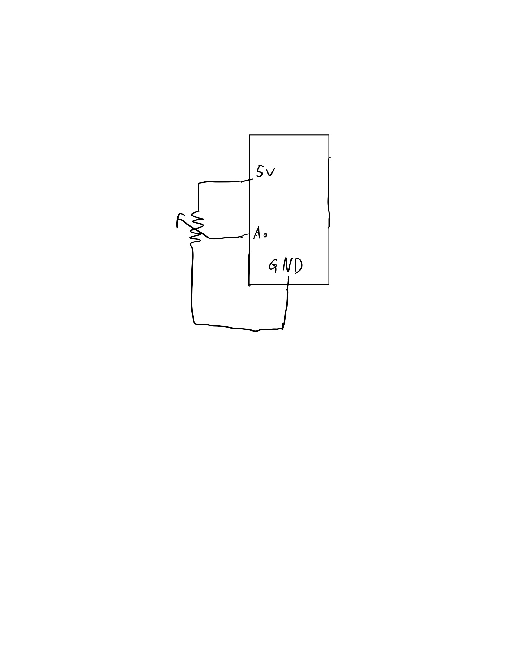
Exercise 1: The value obtained from the potentiometer makes the ellipse in p5 move on the horizontal axis, in the middle of the screen, and nothing on arduino is controlled by p5.
p5.js
let rVal = 0;
let xPos = 0;
let rad = 50;


function setup() {
  createCanvas(400, 400);
  textSize(18);
}

function draw() {
  background(255);

  if (!serialActive) {
    text("Press Space Bar to select Serial Port", 20, 30);
  } else {
    text("Connected", 20, 30);

    xPos = map(rVal, 0, 900, 0, 400);
    // Print the current values
    text('rVal = ' + str(rVal), 20, 50);
    ellipse(xPos, 200, rad, rad);
    text('xPos = ' + str(xPos), 20, 70);

  }

}

function keyPressed() {
  if (key == " ") {
    // important to have in order to start the serial connection!!
    setUpSerial();
  }
}


function readSerial(data) {
  ////////////////////////////////////
  //READ FROM ARDUINO HERE

  if (data != null) {

    let fromArduino = split(trim(data), ",");

    if (fromArduino.length == 1) {
      rVal = fromArduino[0];
    }

    //////////////////////////////////
    //SEND TO ARDUINO HERE (handshake)
    //////////////////////////////////
    let sendToArduino = 1 + "\n";
    writeSerial(sendToArduino);
  }
}
Arduino
void setup() {
  Serial.begin(9600);
  //pinMode(LED_BUILTIN, OUTPUT);

//start the handshake
  while (Serial.available() <= 0) {
    //digitalWrite(LED_BUILTIN, HIGH);
    Serial.println("0,0"); // send a starting message
    delay(300);
    //digitalWrite(LED_BUILTIN, LOW);
    delay(50);

  }
}

void loop() {
  // wait for data from p5 before doing something
  while (Serial.available()) {
     //digitalWrite(LED_BUILTIN, HIGH);
    int isMoving = Serial.parseInt();
    if (Serial.read() == '\n') {
      int photoVal = analogRead(A0);
      delay(5);
      Serial.println(photoVal);
   }
  }
  //digitalWrite(LED_BUILTIN, LOW);
}
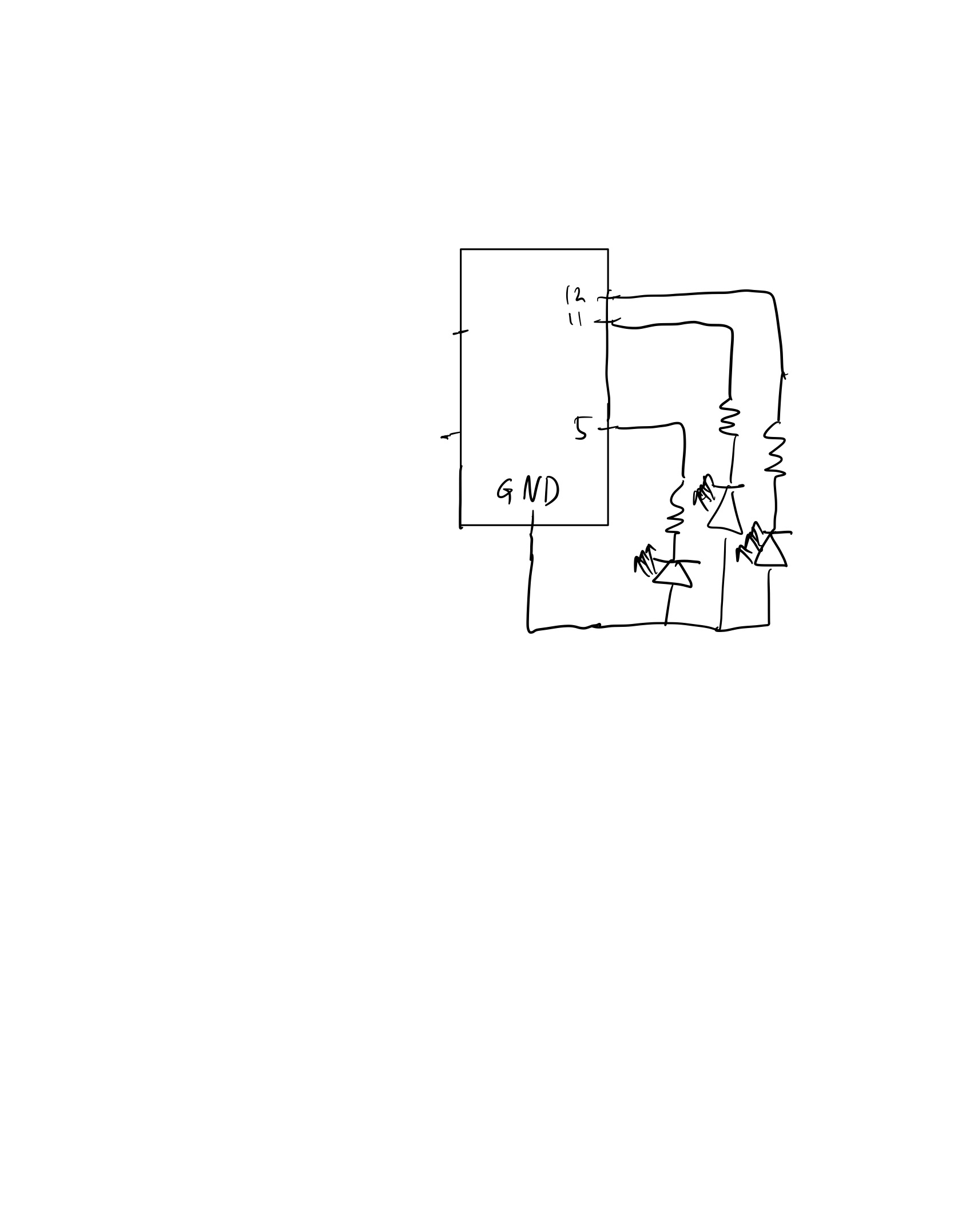
Exercise 2: Change the LED brightness by moving the ellipse on p5.js left or right.
let left = 0;
let right = 0;
let brightness = 0;
let rad = 50;

function setup() {
  createCanvas(400, 400);
  textSize(18);
}

function draw() {
  background(255);

  if (!serialActive) {
    text("Press Space Bar to select Serial Port", 20, 30);
  } else {
    text("Connected", 20, 30);

    //the x position of the cirlce will control the brightness of the LED
    xPos = mouseX;
    ellipse(xPos, 200, rad, rad);
    brightness = map(xPos, 0, 400, 0, 255);
    brightness = int(brightness);

    // Print the current values
    text('Brightness = ' + str(brightness), 20, 60);
    text('xPos = ' + str(xPos), 20, 90);

  }

}

function keyPressed() {
  if (key == " ") {
    // important to have in order to start the serial connection!!
    setUpSerial();
  }
}


function readSerial(data) {
  ////////////////////////////////////
  //READ FROM ARDUINO HERE
  ////////////////////////////////////

  if (data != null) {

    let fromArduino = split(trim(data), ",");
    if (fromArduino.length == 1) {
      // we're not getting input from arduino
    }
    //////////////////////////////////
    //SEND TO ARDUINO HERE (handshake)
    //////////////////////////////////
    let sendToArduino = brightness + "\n";
    writeSerial(sendToArduino);
  }
}
Arduino
int ledPin = 5;

void setup() {
  Serial.begin(9600);
  pinMode(LED_BUILTIN, OUTPUT);
  pinMode(ledPin, OUTPUT);
  // start the handshake
  while (Serial.available() <= 0) {
    digitalWrite(LED_BUILTIN, HIGH); // on/blink while waiting for serial data
    Serial.println("0,0"); // send a starting message
    delay(300);            // wait 1/3 second
    digitalWrite(LED_BUILTIN, LOW);
    delay(50);
  }
}

void loop() {
  // wait for data from p5 before doing something
  while (Serial.available()) {
    digitalWrite(LED_BUILTIN, HIGH); // led on while receiving data
    int brightness = Serial.parseInt();
    if (Serial.read() == '\n') {
      delay(5);
      Serial.println("1");
    }
    analogWrite(ledPin, brightness);
  }
  digitalWrite(LED_BUILTIN, LOW);
}
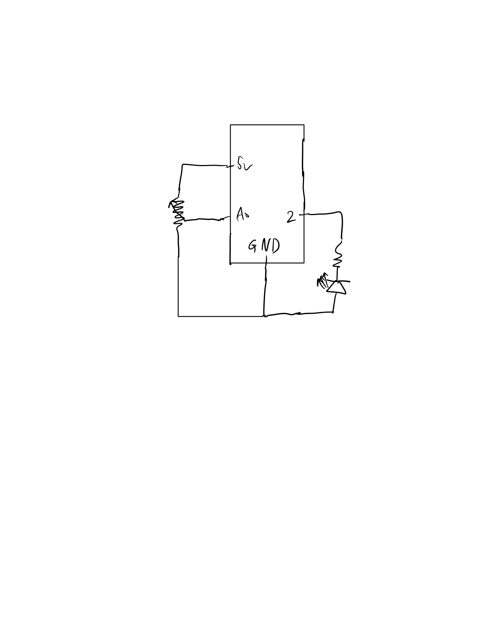
Exercise 3: Alter the gravity wind example to make the LED light up and turn off every time the ball bounces , and control the wind using potentiometer.
p5.js
let velocity;
let gravity;
let position;
let acceleration;
let wind;
let drag = 0.99;
let mass = 50;

function setup() {
  createCanvas(640, 360);
  noFill();
  position = createVector(width/2, 0);
  velocity = createVector(0,0);
  acceleration = createVector(0,0);
  gravity = createVector(0, 0.5*mass);
  wind = createVector(0,0);
}

function draw() {
  background(255);

  if (!serialActive) {
    text("Press Space Bar to select Serial Port", 20, 30);
  } else {
    applyForce(wind);
    applyForce(gravity);
    velocity.add(acceleration);
    velocity.mult(drag);
    position.add(velocity);
    acceleration.mult(0);

    fill(0);
    ellipse(position.x, position.y, mass, mass);
    if (position.y > height - mass / 2) {
      velocity.y *= -0.9; // A little dampening when hitting the bottom
      position.y = height - mass / 2;
      isBouncing = 1;
    } else {
      isBouncing = 0;
    }
  }
}

function applyForce(force){
  // Newton's 2nd law: F = M * A
  // or A = F / M
  let f = p5.Vector.div(force, mass);
  acceleration.add(f);
}


function keyPressed() {
  if (key == " ") {
    // important to have in order to start the serial connection!!
    setUpSerial();
  } else if (key == "ENTER") {
    mass = random(15, 80);
    position.y = -mass;
    velocity.mult(0);
  }
}

function readSerial(data) {
  if (data != null) {
    // make sure there is actually a message
    // split the message
    let fromArduino = split(trim(data), ",");
    // if the right length, then proceed
    if (fromArduino.length == 1) {
      // only store values here
      // do everything with those values in the main draw loop
      let potValue = int(fromArduino[0]);

      //change the wind based on the potentiometer value
      wind.x = map(potValue, 0, 900, -5, 5);
    }

    //////////////////////////////////
    //SEND TO ARDUINO HERE (handshake)
    //////////////////////////////////
    let sendToArduino = isBouncing + "\n";
    writeSerial(sendToArduino);
  }
}
Arduino
int ledPin = 5;
const int potPin = A0;

void setup() {
  Serial.begin(9600);
  pinMode(LED_BUILTIN, OUTPUT);
  pinMode(ledPin, OUTPUT);
  pinMode(potPin, INPUT);

  // start the handshake
  while (Serial.available() <= 0) {
    digitalWrite(LED_BUILTIN, HIGH); // on/blink while waiting for serial data
    Serial.println("0,0"); // send a starting message
    delay(300);            // wait 1/3 second
    digitalWrite(LED_BUILTIN, LOW);
    delay(50);
  }
}

void loop() {
  // wait for data from p5 before doing something
  while (Serial.available()) {
    digitalWrite(LED_BUILTIN, HIGH); // led on while receiving data
    digitalWrite(ledPin, LOW);
    int isBouncing = Serial.parseInt();
    if (Serial.read() == '\n') {
      int potValue = analogRead(potPin);
      delay(5);
      Serial.println(potValue);
    }
    // Set LED brightness based on whether bouncing.
    if (isBouncing == 1) {
      digitalWrite(ledPin, HIGH);
    } else {
      digitalWrite(ledPin, LOW);
    }
  }
  digitalWrite(LED_BUILTIN, LOW);
}
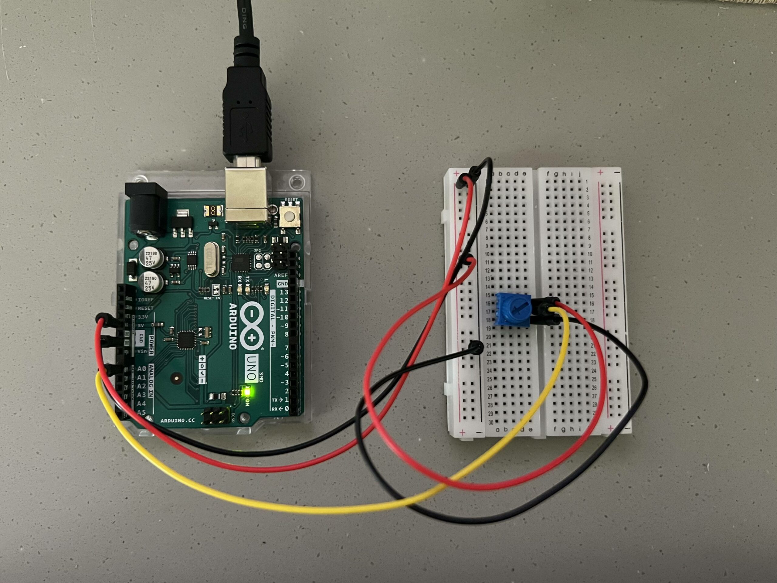
Demo

