Final Project Proposal: Togyzkumalak

CONCEPT

For my final project, I will create a version of the Kazakh traditional two-player board game, Togyzkumalak (transl. “nine pebbles”). Each player will be using three buttons connected through Arduino to p5 to control their movements in the game (left, right, enter). On p5 will be the visualization of the board, with 9 playing pits and 1 storehouse for each player. Players will use buttons to choose which pit to take the pebbles from.

Players will be given a minute to make their move. The player with the highest score wins (total of pebbles captured). To add something new to the game, chance games will be played between the turns.

        • after every 3rd turn, a player will be given a chance to roll a die in the game. The die will have both negative ((-3) to (-1)) and positive numbers (1 to 3). The number shown will be added to the score of the player.
        • after every 7th turn, a player will be given a choice between three cards shown backward. One of the cards will be empty, one will have a challenge, and the last one will have a bonus. Drawing an empty card will safely return you to the game. Drawing a challenge card will make decrease your turn time to 30s for the next two turns. Drawing a bonus card will add 1 more minute to your turn time for the next two turns.

To learn more about the rules refer to my previous post.

ARDUINO

Description

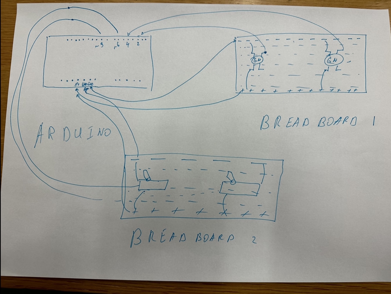
My Arduino setup will consist of 8 buttons:

        • 3 buttons for each player (left, enter, right);
        • 2 shared buttons (instructions, return to the main menu).

Each of the buttons will be assigned a value directly related to its function (ex. user1_right_btn, instructions_btn, etc). On button press, this value will be sent to p5.

p5 will be sending information to Arduino every second. The information to be received is:

        • which player’s turn is it – to enable playing player’s buttons and disable not playing player’s buttons during playing player’s turn.
        • the number of turns played so far (tentative) – to switch controls after every 3rd and 7th turn to play the chance games.
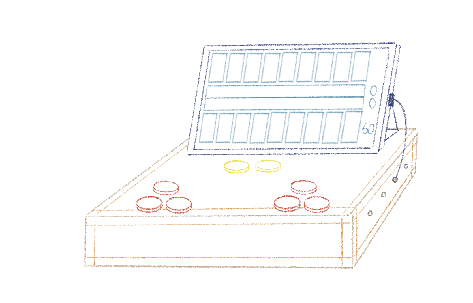
DESIGN

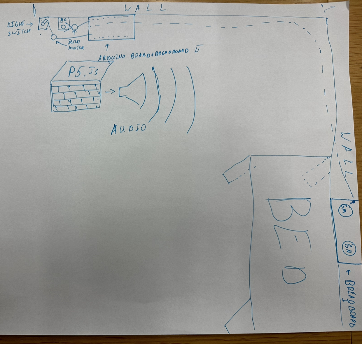
To add to the experience, I want to laser cut a custom playing board that will feature 8 arcade buttons for controls and an Ipad for the game display. The Arduino board and cord will be snuggly hidden under the box-like board. Below is the picture for reference:

Game Setup

P5

Description

P5 will receive information about the button pressed on Arduino to do one of the following:

        • userX_left_btn” – move the user selection window from the current pit to index-1 with min_index = 0 (when reaching the left limit of the board the selection doesn’t move).
        • userX_right_btn” – move the user selection window from the current pit to index+1 with max_index = 8 (when reaching the right limit of the board the selection doesn’t move).
        • userX_enter_btn” – select the pit -> pebble distribution -> update turns played so far -> update current_player value.
        • instructions_btn” –
            • if the instructions window is not displayed and the button is pressed -> display the instructions window,
            • if the instructions window is displayed and the button is pressed -> close the instructions window.
        • mainMenu_btn” – end game and display main menu window.

P5 will send information about which player’s turn is it and the turns played by the current player so far.

Design

The whole game will be displayed on p5. There will be 3 game states to display three different windows:

        • gameState = “start” -> display main menu
            • instructions display;
            • “play” button (triggered by synch press of the “enter” button by two players);
        • gameState = “playing” -> display the game
            • game board (9 even-sized playing pits and one big storehouse for each player);
            • scores;
            • timer (if the player didn’t press “enter” by the end of the timer -> currently selected pit will be played);
            • chance games displayed over the game board (after every 3rd and 7th turn);
        • gameState = “end” -> display end screen with scores
            • scores;
            • end message;
            • “return to main menu button” (same as the one during the game);

It would be nice to have animation during:

        • pebble distribution – view each pebble put into a pit;
        • die roll – rotation of a cube or change of the number on the moving flat square;
        • card picking – rotation of a card or some revealing movement.

To add to the experience relevant sound effects will be played.

Week 11 – Final Project Proposal

Sound Canvas – a sound visualizing musical instrument 

Concept

A sound visualization instrument that allows you to both make music and visualize it on the p5 screen. Someone who cannot hear can see the visualization of a sound, and hence will enjoy the instrument in a different way. Similarly, someone who cannot see can hear the sounds, and hence enjoy it differently too. Overall, the Sound Canvas concept presents a unique and accessible approach to music creation and enjoyment, integrating sound visualization, interactivity, and artistic elements.

  • 3 different tone types (fast/medium/slow) – change according to brightness of light in the room – dimmer the light, calmer the tone
      • Light sensor to specify ranges of brightness in which each tone plays so that if brightness within a certain range, a certain type of music will be played in the background 
      • The tone might be played on the buzzer or the computer (TBD)
      • The background color of the p5 screen will represent the tone type, for example, fast will be represented by a specific color such as red
  • 3-6 Buttons to play additional sounds/notes when pressed
      • Each button will have a specific sound associated to it
      • When pressed, the associated sound will be played (added on top of the background music)
      • The sound will either be played on the computer or the buzzer (TBD)
      • Whenever a button is pressed, an LED will light up as feedback
  • Tone volume/pitch can be changed using either a distance sensor or a potentiometer (TBD)
      • volume/pitch displayed on the p5 screen
  • Sound Visualization on the p5 screen with shapes/patterns/colors
      • Inspiration: https://patatap.com/ 
      • Every button when pressed will also display a pattern/color/shape associated to the button on the p5 screen

Arduino

For the Arduino end, as mentioned, sensors and buttons will be arranged in a box. I might integrate a motor as well that moves something, for example a music record, according to the sensor values.

Inputs and Outputs:

    • From light sensor – will send it to p5
    • From distance sensor/potentiometer – will send it to p5/use to control volume of buzzer
    • From buttons – will light up corresponding LEDs and send to p5 
    • From P5 – indication if instrument turned on/off from p5 screen – use to turn corresponding power LED on/off
    • LEDs to indicate if instrument is on or if any button is pressed (feedback)
    • Buzzer (to play background sound/button sounds)

P5

The P5 screen will first present instructions on how to use the instrument. Once the experience begins, the screen will show a visualization of the music created using input from the sensors. This way, every user will, in a way, create an art piece that is theirs. So, not only can the user change their motion/touch to change the output sound but to also add something to their sketch. Also, P5 will have some buttons that, when pressed, will send output to Arduino – for example LEDs light up when Start button is pressed or if sensor value exceeds a threshold or maybe different tone/sound/volume options available on screen that will be used to change the output melody.

Inputs and outputs

    • Use light sensor value from Arduino to change tone type and screen background color
    • Use inputs from buttons that Arduino sends to draw shapes/patterns on the screen
    • Display details such as volume/tone type in the corner of the screen

Final Project Proposal – Radar

Concept

As someone who is interested in physical computing, I have been inspired by previous DIY radar projects that use ultrasonic sensors and servo motors to detect objects in real-time. However, to make my project more original and challenging, I will use P5.js, a JavaScript library for creative coding, instead of Processing, which is commonly used in similar projects. By incorporating P5.js, I hope to create a unique and interactive radar system that combines hardware and software components. The concept of the project is to build a radar system that can detect objects and display their location and distance in real-time. The system will consist of an ultrasonic sensor, a servo motor, an Arduino board, and a computer running a P5.js program.

Technical aspect

For the Arduino program, I plan to use the ultrasonic sensor to detect the distance of objects in front of it. I will then use a servo motor to rotate the sensor and sweep it across a 180-degree arc. At each angle, the program will read the distance measurement and send this data to the P5.js program over the serial port. Additionally, I plan to control an LED to indicate the presence of an object within a certain distance threshold.

The P5.js program will receive the data from the Arduino program and use it to display the location of the detected object on a radar screen. Using polar coordinates, the program will map the distance and angle of each object and display them as a dot on the radar screen. The program will also include a graphical user interface (GUI) that allows me to adjust the distance threshold and other parameters.

To communicate between the Arduino and P5.js programs, I will send data over the serial port. The Arduino program will send the angle and distance of each detected object, as well as the state of the LED. The P5.js program will use this data to update the radar screen and the GUI.

Final Project: Akyn

  • The finalized concept for the project
    • Akyn is a smart system that makes morning and night routines more pleasant. This device has 2 buttons, one for mornings and one for nights.
      • When the “Good Night” button is pressed, the system turns off the lights and AC with the servo motor. While Arduino does that, P5 will wish a random good night phrase(chosen out of a pre-established array of words) and notify the person what time the alarm is set and how many hours are left.
      • When the “Good Morning” button is pressed, Arduino will turn on the AC. P5 will greet the person with a good morning text, announce the daily schedule from the Google Calendar, announce how many emails in the user’s Gmail are, and play a random motivational song.
  • Design and description
    • As stated above, each button changes the state of the appropriate button variable, which when active will trigger either only one servo motor(Lights) or both of them(AC). When each button is active it sends a 0 or 1 code to P5 which will trigger the “Good Morning” code for 0 and “Good Night” code for 1(description of actions are at the top). P5 code fetches data from a person’s Google Calendar and Gmail which after some modifications will announce out loud. P5 will send a dummy value back to Arduino since the communication works one way only.

Room Design with Akyn

Akyn  Arduino  +  Breadboard

FINAL PROJECT IDEA

CONCEPT

For now, my plan is to build a car which will be controlled using hand gestures from the user. To do this, the control system will track the user’s hand position, interpret the hand gestures made by the user and translated the hand gestures into commands that’d be used in moving the car.

IMPLEMENTATION

My goal is to develop a control system for a car by integrating the P5JS tracking system. This system will enable the car to be controlled through hand gestures made by the user. To achieve this, I will utilize the advanced capabilities of PoseNet for detecting the user’s hand position accurately. By interpreting the hand gestures made by the user, the system will translate them into commands that can be used to move the car.

The P5JS tracking system will be responsible for monitoring and analyzing the forward and backward movements of the user’s hand to control the car accordingly. It will allow the user to steer the car in the desired direction by moving their hand forward, backward, left or right. The tracking system will accurately detect the user’s hand position and interpret the hand gestures in real-time, enabling seamless and responsive control of the car.


WEEK 11

PROMPT 1

Code

//declaring variables
let serial;
let photoValue = 0;
let xPos = 0;
let Size = 80;
let yPos = 200;

function setup() {
  createCanvas(400, 400);
  serial = new p5.SerialPort();
  serial.open('/dev/tty.usbmodem1301');
  serial.on('data', readSerialData); // call readSerialData when new data is received
}

function draw() {
  background(220);
  fill("red");
  ellipse(xPos, yPos, Size, Size);
}

function readSerialData() {
  let data = serial.readLine(); // read the incoming data
  if (data) {
    photoValue = Number(data); // convert the data to a number
    xPos = map(photoValue, 0, 1023, 0, width); // map the photo sensor value to the x-position of the ellipse
  }
}

Video


PROMPT 2

CODE

let serial;
let brightness = 0; // variable to store LED brightness

function setup() {
  serial = new p5.SerialPort();
  serial.open('/dev/tty.usbmodem1301');
  createCanvas(400, 400);
}

function draw() {
  background(220);
  text("LED Brightness: " + brightness, 50, 50);

  // send data to Arduino over serial
  if (frameCount % 10 == 0) {
    serial.write(brightness);
  }
}

function keyPressed() {
  if (keyCode === UP_ARROW && brightness < 255) {
    brightness += 10; // increase brightness by 10
  } else if (keyCode === DOWN_ARROW && brightness > 0) {
    brightness -= 10; // decrease brightness by 10
  }
}

VIDEO


PROMPT 3

CODE

let gravity;
let position;
let acceleration;
let wind;
let drag = 0.99;
let mass = 50;
let lightVal = 0;
let ledState = false;

let serial;
let led;

function setup() {
  createCanvas(640, 360);
  noFill();
  position = createVector(width/2, 0);
  velocity = createVector(0,0);
  acceleration = createVector(0,0);
  gravity = createVector(0, 0.5*mass);
  wind = createVector(0,0);

  serial = new p5.SerialPort();
  serial.open('/dev/tty.usbmodem1301');
  serial.on("data", serialEvent);

  led = new p5.SerialPort();
  led.open('/dev/tty.usbmodem1301');
}

function draw() {
  background(255);

  wind.x = map(lightVal, 0, 1023, -1, 1);

  applyForce(wind);
  applyForce(gravity);
  velocity.add(acceleration);
  velocity.mult(drag);
  position.add(velocity);
  acceleration.mult(0);
  ellipse(position.x,position.y,mass,mass);

  if (position.y > height-mass/2) {
    velocity.y *= -0.9;  // A little dampening when hitting the bottom
    position.y = height-mass/2;
    led.write("L"); // Turn off the LED when the ball hits the ground
  } else {
    led.write("H"); // Turn on the LED when the ball is in the air
  }
}

function applyForce(force){
  // Newton's 2nd law: F = M * A
  // or A = F / M
  let f = p5.Vector.div(force, mass);
  acceleration.add(f);
}

function serialEvent() {
  lightVal = Number(serial.readLine());
}

function keyPressed(){
  if (keyCode==LEFT_ARROW){
    wind.x=-1;
  }
  if (keyCode==RIGHT_ARROW){
    wind.x=1;
  }
  if (key==' '){
    mass=random(15,80);
    position.y=-mass;
    velocity.mult(0);
  }
}

VIDEO


Arduino + p5js in class exercises (Saamia and Khadija)

Exercise 1:

For our first exercise, we used a light sensor as the analog input value for the movement of the ellipse on the p5js screen. The rVal from Arduino is used to plot the x coordinate of the ellipse.

p5js code:

//exercise 1 p5js
let rVal = 0;
let alpha = 255;

function setup() {
  createCanvas(640, 480);
  textSize(18);
}

function draw() {
  
  if (key == " ") 
  {
    // important to have in order to start the serial connection!!
    setUpSerial();
  }
  
  // one value from Arduino controls the background's red color
  background(map(rVal, 0, 1023, 0, 255), 255, 255);

  // the other value controls the text's transparency value
  fill(255, 0, 255, map(alpha, 0, 1023, 0, 255));

  if (!serialActive) 
  {
    text("Press Space Bar to select Serial Port", 20, 30);
  } else 
  {
    ellipse(rVal/2,240,100,100);
  }
}

function keyPressed() {
  if (key == " ") 
  {
    // important to have in order to start the serial connection!!
    setUpSerial();
  }
}

// This function will be called by the web-serial library
// with each new line of data. The serial library reads
// the data until the newline and then gives it to us through
// this callback function
function readSerial(data) {
  ////////////////////////////////////
  //READ FROM ARDUINO HERE
  ////////////////////////////////////

  if (data != null) 
  {
    // make sure there is actually a message
    // split the message
    let fromArduino = split(trim(data), ",");
    // if the right length, then proceed
    if (fromArduino.length == 2) 
    {
      // only store values here
      // do everything with those values in the main draw loop
      
      // We take the string we get from Arduino and explicitly
      // convert it to a number by using int()
      // e.g. "103" becomes 103
      rVal = int(fromArduino[0]);
      alpha = int(fromArduino[1]);
    }
  }
}

Arduino Code:

//exercise 1 arduino

void setup() {
  Serial.begin(9600); 
  pinMode(LED_BUILTIN, OUTPUT);
// start the handshake
  while (Serial.available() <= 0) 
{
    Serial.println("0,0"); // send a starting message
    delay(300);            // wait 1/3 second
  }
}
void loop() 
{
  // wait for data from p5 before doing something
    while (Serial.available()) 
{
    digitalWrite(LED_BUILTIN, HIGH); // led on while receiving data

  // Read sensor value
  int sensorValue = analogRead(A0);
   Serial.print(sensorValue);
  // Map sensor value to screen width
  int screenValue = map(sensorValue, 0, 1023, 0, 800);

  // Send mapped value to p5.js
  Serial.println(screenValue);
  delay(50); //    for stability
}
digitalWrite(LED_BUILTIN, LOW);
}

Exercise 2:

In the second exercise, we implemented a slider to adjust the brightness of an LED using Arduino. The current position of the slider, accessed through slider.value(), was stored as the variable “brightness”, and subsequently transmitted to Arduino as the new brightness level for the LED.

p5js Code:

//exercise 2 p5js

let brightness;
function setup() 
{
  createCanvas(640, 480);
  textSize(18);
  slider = createSlider(0, 255, 0); 
  slider.position(85, 140);
}

function draw() 
{
  if (!serialActive) 
{
    text("Press Space Bar to select Serial Port", 20, 30);
  } 
else 
{
    text("connected", 20, 30);
    brightness = slider.value();
  }
  brightness = slider.value();
  //readSerial();
  if(mouseIsPressed)
{
    readSerial();
  }
}

function mouseIsPressed()
{
  readSerial();
}

function keyPressed() {
  if (key == " ") 
{
    // important to have in order to start the serial connection!!
    setUpSerial();
  }
}
function readSerial(data) 
{
    console.log(brightness);
    let sendToArduino = brightness+"\n";
    writeSerial(sendToArduino);

}

Arduino Code:

//exercise 2 arduino

int ledpin = 5;
void setup() {
  // Start serial communication so we can send data
  // over the USB connection to our p5js sketch
  Serial.begin(9600);

  // Outputs on these pins
  pinMode(ledpin, OUTPUT);

  //Blink them so we can check the wiring
  digitalWrite(ledpin, HIGH);
    delay(200);
  digitalWrite(ledpin, LOW);

  // start the handshake
  while (Serial.available() <= 0) 
{
    Serial.println("0");
    delay(300);
  }
}

void loop() {
  // wait for data from p5 before doing something
  while (Serial.available()) 
{
    int brightness = Serial.parseInt();

    if(Serial.read() == '\n')
{
      //Serial.println(brightness);
      analogWrite(ledpin, brightness);
    }
    analogWrite(ledpin, brightness);
  }
 
}

Exercise 3:

For this last exercise, we used an ultrasonic sensor to sense the distance and use this variable to change the wind movement in the p5js movement of the ball. The data values of the sensor ranged from 0 to around 3000 and therefore for any value below 1000 the wind blew from left to right and if the value was above 1000 wind and the ball moved towards the left.

p5js Code:

//p5js exercise 3
//declare variables
let velocity;
let gravity;
let position;
let acceleration;
let wind;
let drag = 0.99;
let mass = 50;
let value = 1401;

function setup() 
{
  createCanvas(640, 360); //create canvas
  noFill();
  position = createVector(width/2, 0);
  velocity = createVector(0,0);
  acceleration = createVector(0,0);
  gravity = createVector(0, 0.5*mass);
  wind = createVector(0,0);
}

function display()
{
  text("Press Space Bar to Start Serial Port", width/2 - 109, height/2 - 5);
}

function draw() {
background(255);
if (serialActive) //if the serial is active
{
  applyForce(wind);
  applyForce(gravity);
  velocity.add(acceleration);
  velocity.mult(drag);
  position.add(velocity);
  acceleration.mult(0);
  ellipse(position.x,position.y,mass,mass);
      if (position.y > height-mass/2) //if the ball touches the bottom
      {
      velocity.y *= -0.9; // A little dampening when hitting the bottom
      position.y = height-mass/2;
      }
}
else //if serial not active
  {
  fill(0);
  display();
  }
}

function applyForce(force)
  {
  // Newton's 2nd law: F = M * A
  // or A = F / M
  let f = p5.Vector.div(force, mass);
  acceleration.add(f);
  }

function keyPressed()
{
  if (key==' ')
  {
  setUpSerial();
  }

if (keyCode == UP_ARROW) //if up arrow is pressed
  {
  mass=random(15,80);
  position.y=-mass;
  velocity.mult(0);
  }
}

function readSerial(data) //call back function
{
let sendToArduino = value + "\n"; //sends value to Arduino with \n added
writeSerial(sendToArduino); //write to Arduino
  if (data != null) //if some information is received
  {
  console.log(data);
    if (data < 1000) //if the distance is less than 1000
    {
    wind.x = 1; //the wind blows to the right
    }
    else if (data > 1000) //if the distance is more than 1000
    {
    wind.x = -1; //the wind blows to the left
    }
  }
}

Arduino Code:

//exercise 3 arduino code
int value = 0;
const int trigPin = 7; //trig pin of Sensor
const int echoPin = 13; //echo pin of Sensor
int distance = 0; //distance data from sensor

void setup()
{
Serial.begin(9600); // Start serial communication at 9600 baud

//set the sensor pins as output and input 
pinMode(trigPin, OUTPUT);
pinMode(echoPin, INPUT);

while (Serial.available() <= 0)
{
  Serial.println(1400);
}
}

void loop()
{
//wait for p5js
while (Serial.available())
{
sensorReading(); //reading data from sensor
value = Serial.parseInt(); //parsing from the serial written data from p5js
}
}

//to read the sensor and find distance
void sensorReading()
{
//Send a short low pulse
digitalWrite(trigPin, LOW);
delay(2); //delay to avoid complications
digitalWrite(trigPin, HIGH); //sends a high pulse for 10 microseconds
delay(10);
digitalWrite(trigPin, LOW); //turn off the ping pin
distance = pulseIn(echoPin, HIGH); //Measure the duration of the ultrasonic pulse and calculate the distance
Serial.println(distance); //print the serial from distance
}

Video:

week-15 exercise + final idea

Exercise 1: The value obtained from the potentiometer makes the ellipse in p5 move on the horizontal axis, in the middle of the screen, and nothing on Arduino is controlled by p5.

p5.js

let rVal = 0;
let xPos = 0;
let rad = 50;


function setup() {
  createCanvas(400, 400);
  textSize(18);
}  

function draw() {
  background(255);

  if (!serialActive) {
    text("Press Space Bar to select Serial Port", 20, 30);
  } else {
    text("Connected", 20, 30);
    
    xPos = map(rVal, 0, 900, 0, 400);
    // Print the current values
    text('rVal = ' + str(rVal), 20, 50);
    ellipse(xPos, 200, rad, rad);
    text('xPos = ' + str(xPos), 20, 70);

  }
  
}

function keyPressed() {
  if (key == " ") {
    // important to have in order to start the serial connection!!
    setUpSerial();
  }
}


function readSerial(data) {
  ////////////////////////////////////
  //READ FROM ARDUINO HERE
  
  if (data != null) {
    
    let fromArduino = split(trim(data), ",");

    if (fromArduino.length == 1) {
      rVal = fromArduino[0];
    }

    //////////////////////////////////
    //SEND TO ARDUINO HERE (handshake)
    //////////////////////////////////
    let sendToArduino = 1 + "\n";
    writeSerial(sendToArduino);
  }
}

Arduino

void setup() {
  Serial.begin(9600);
  //pinMode(LED_BUILTIN, OUTPUT);

//start the handshake
  while (Serial.available() <= 0) {
    //digitalWrite(LED_BUILTIN, HIGH);
    Serial.println("0,0"); // send a starting message
    delay(300);
    //digitalWrite(LED_BUILTIN, LOW);
    delay(50);

  }
}

void loop() {
  // wait for data from p5 before doing something
  while (Serial.available()) {
     //digitalWrite(LED_BUILTIN, HIGH);
    int isMoving = Serial.parseInt();
    if (Serial.read() == '\n') {
      int photoVal = analogRead(A0); 
      delay(5);
      Serial.println(photoVal);
   }
  }
  //digitalWrite(LED_BUILTIN, LOW);
}

Exercise 2: Change the LED brightness by moving the ellipse on p5.js left or right.

let left = 0;
let right = 0;
let brightness = 0;
let rad = 50;

function setup() {
  createCanvas(400, 400);
  textSize(18);
}  

function draw() {
  background(255);

  if (!serialActive) {
    text("Press Space Bar to select Serial Port", 20, 30);
  } else {
    text("Connected", 20, 30);

    //the x position of the cirlce will control the brightness of the LED
    xPos = mouseX;
    ellipse(xPos, 200, rad, rad);
    brightness = map(xPos, 0, 400, 0, 255);
    brightness = int(brightness);
    
    // Print the current values
    text('Brightness = ' + str(brightness), 20, 60);
    text('xPos = ' + str(xPos), 20, 90);

  }
  
}

function keyPressed() {
  if (key == " ") {
    // important to have in order to start the serial connection!!
    setUpSerial();
  }
}


function readSerial(data) {
  ////////////////////////////////////
  //READ FROM ARDUINO HERE
  ////////////////////////////////////
  
  if (data != null) {
    
    let fromArduino = split(trim(data), ",");
    if (fromArduino.length == 1) {
      // we're not getting input from arduino
    }
    //////////////////////////////////
    //SEND TO ARDUINO HERE (handshake)
    //////////////////////////////////
    let sendToArduino = brightness + "\n";
    writeSerial(sendToArduino);
  }
}

Arduino

int ledPin = 5;

void setup() {
  Serial.begin(9600);
  pinMode(LED_BUILTIN, OUTPUT);
  pinMode(ledPin, OUTPUT);
  // start the handshake
  while (Serial.available() <= 0) {
    digitalWrite(LED_BUILTIN, HIGH); // on/blink while waiting for serial data
    Serial.println("0,0"); // send a starting message
    delay(300);            // wait 1/3 second
    digitalWrite(LED_BUILTIN, LOW);
    delay(50);
  }
}

void loop() {
  // wait for data from p5 before doing something
  while (Serial.available()) {
    digitalWrite(LED_BUILTIN, HIGH); // led on while receiving data
    int brightness = Serial.parseInt();
    if (Serial.read() == '\n') {
      delay(5);
      Serial.println("1");
    }
    analogWrite(ledPin, brightness);
  }
  digitalWrite(LED_BUILTIN, LOW);
}

Exercise 3: Alter the gravity wind example to make the LED light up and turn off every time the ball bounces , and control the wind using potentiometer.

p5.js

let velocity;
let gravity;
let position;
let acceleration;
let wind;
let drag = 0.99;
let mass = 50;

function setup() {
  createCanvas(640, 360);
  noFill();
  position = createVector(width/2, 0);
  velocity = createVector(0,0);
  acceleration = createVector(0,0);
  gravity = createVector(0, 0.5*mass);
  wind = createVector(0,0);
}

function draw() {
  background(255);
  
  if (!serialActive) {
    text("Press Space Bar to select Serial Port", 20, 30);
  } else {
    applyForce(wind);
    applyForce(gravity);
    velocity.add(acceleration);
    velocity.mult(drag);
    position.add(velocity);
    acceleration.mult(0);

    fill(0);
    ellipse(position.x, position.y, mass, mass);
    if (position.y > height - mass / 2) {
      velocity.y *= -0.9; // A little dampening when hitting the bottom
      position.y = height - mass / 2;
      isBouncing = 1;
    } else {
      isBouncing = 0;
    }
  }
}

function applyForce(force){
  // Newton's 2nd law: F = M * A
  // or A = F / M
  let f = p5.Vector.div(force, mass);
  acceleration.add(f);
}


function keyPressed() {
  if (key == " ") {
    // important to have in order to start the serial connection!!
    setUpSerial();
  } else if (key == "ENTER") {
    mass = random(15, 80);
    position.y = -mass;
    velocity.mult(0);
  }
}

function readSerial(data) {
  if (data != null) {
    // make sure there is actually a message
    // split the message
    let fromArduino = split(trim(data), ",");
    // if the right length, then proceed
    if (fromArduino.length == 1) {
      // only store values here
      // do everything with those values in the main draw loop
      let potValue = int(fromArduino[0]);
      
      //change the wind based on the potentiometer value
      wind.x = map(potValue, 0, 900, -5, 5);
    }

    //////////////////////////////////
    //SEND TO ARDUINO HERE (handshake)
    //////////////////////////////////
    let sendToArduino = isBouncing + "\n";
    writeSerial(sendToArduino);
  }
}

Arduino

int ledPin = 5;
const int potPin = A0;

void setup() {
  Serial.begin(9600);
  pinMode(LED_BUILTIN, OUTPUT);
  pinMode(ledPin, OUTPUT);
  pinMode(potPin, INPUT);
  
  // start the handshake
  while (Serial.available() <= 0) {
    digitalWrite(LED_BUILTIN, HIGH); // on/blink while waiting for serial data
    Serial.println("0,0"); // send a starting message
    delay(300);            // wait 1/3 second
    digitalWrite(LED_BUILTIN, LOW);
    delay(50);
  }
}

void loop() {
  // wait for data from p5 before doing something
  while (Serial.available()) {
    digitalWrite(LED_BUILTIN, HIGH); // led on while receiving data
    digitalWrite(ledPin, LOW);
    int isBouncing = Serial.parseInt();
    if (Serial.read() == '\n') {
      int potValue = analogRead(potPin);
      delay(5);
      Serial.println(potValue);
    }
    // Set LED brightness based on whether bouncing.
    if (isBouncing == 1) {
      digitalWrite(ledPin, HIGH);
    } else {
      digitalWrite(ledPin, LOW);
    }
  }
  digitalWrite(LED_BUILTIN, LOW);
}

Final Project Idea

Concept

For the final project, me and Sanjana are thinking of creating a Virtual Fruit Ninja. We want to take the concept of this mobile game to the next level by creating an immersive and interactive game experience allowing players to slice fruits virtually with their hands! The following project and our love for the game fruit ninja is the inspiration for this project: (https://naziafakhruddin.medium.com/gesture-controlled-flower-art-with-ml5-js-posenet-and-p5-js-61b98fa3fc68)

For this project, we are thinking of using the ml5 library, built on top of Tensor.js, and the PoseNet function to accurately track the position of the player’s hand in real time through the camera video. The goal is to create a seamless integration between the player’s hand movements and a virtual sword or blade in the game, simulating the experience of slicing real fruits with a knife.

The game mechanics will be intuitive and engaging. Players can wave their hands across the screen to slice the fruits as they appear, and the PoseNet function will accurately track their hand movements in real time, providing precise and responsive slicing actions. We will also leverage p5.js to create visually appealing graphics and animations, creating an engaging game environment that enhances the overall gameplay experience.

Challenge

One of the main challenges of this project will be optimizing the game’s performance to ensure smooth gameplay and minimize latency. We will need to carefully understand the output of the PoseNet model and use the information to update the virtual sword’s position and orientation in real-time.

Arduino + p5js in class exercises (Saamia and Khadija)

Exercises

Exercise 1:

For our first exercise, we used a light sensor as the analog input value for the movement of the ellipse on the p5js screen. The rVal from Arduino is used to plot the x coordinate of the ellipse.

p5js code:

//exercise 1 p5js
let rVal = 0;
let alpha = 255;

function setup() {
  createCanvas(640, 480);
  textSize(18);
}

function draw() {
  
  if (key == " ") 
  {
    // important to have in order to start the serial connection!!
    setUpSerial();
  }
  
  // one value from Arduino controls the background's red color
  background(map(rVal, 0, 1023, 0, 255), 255, 255);

  // the other value controls the text's transparency value
  fill(255, 0, 255, map(alpha, 0, 1023, 0, 255));

  if (!serialActive) 
  {
    text("Press Space Bar to select Serial Port", 20, 30);
  } else 
  {
    ellipse(rVal/2,240,100,100);
  }
}

function keyPressed() {
  if (key == " ") 
  {
    // important to have in order to start the serial connection!!
    setUpSerial();
  }
}

// This function will be called by the web-serial library
// with each new line of data. The serial library reads
// the data until the newline and then gives it to us through
// this callback function
function readSerial(data) {
  ////////////////////////////////////
  //READ FROM ARDUINO HERE
  ////////////////////////////////////

  if (data != null) 
  {
    // make sure there is actually a message
    // split the message
    let fromArduino = split(trim(data), ",");
    // if the right length, then proceed
    if (fromArduino.length == 2) 
    {
      // only store values here
      // do everything with those values in the main draw loop
      
      // We take the string we get from Arduino and explicitly
      // convert it to a number by using int()
      // e.g. "103" becomes 103
      rVal = int(fromArduino[0]);
      alpha = int(fromArduino[1]);
    }
  }
}

Arduino Code:

//exercise 1 arduino

void setup() {
  Serial.begin(9600); 
  pinMode(LED_BUILTIN, OUTPUT);
// start the handshake
  while (Serial.available() <= 0) 
{
    Serial.println("0,0"); // send a starting message
    delay(300);            // wait 1/3 second
  }
}
void loop() 
{
  // wait for data from p5 before doing something
    while (Serial.available()) 
{
    digitalWrite(LED_BUILTIN, HIGH); // led on while receiving data

  // Read sensor value
  int sensorValue = analogRead(A0);
   Serial.print(sensorValue);
  // Map sensor value to screen width
  int screenValue = map(sensorValue, 0, 1023, 0, 800);

  // Send mapped value to p5.js
  Serial.println(screenValue);
  delay(50); //    for stability
}
digitalWrite(LED_BUILTIN, LOW);
}
Exercise 2:

In the second exercise, we implemented a slider to adjust the brightness of an LED using Arduino. The current position of the slider, accessed through slider.value(), was stored as the variable “brightness”, and subsequently transmitted to Arduino as the new brightness level for the LED.

p5js Code:

//exercise 2 p5js

let brightness;
function setup() 
{
  createCanvas(640, 480);
  textSize(18);
  slider = createSlider(0, 255, 0); 
  slider.position(85, 140);
}

function draw() 
{
  if (!serialActive) 
{
    text("Press Space Bar to select Serial Port", 20, 30);
  } 
else 
{
    text("connected", 20, 30);
    brightness = slider.value();
  }
  brightness = slider.value();
  //readSerial();
  if(mouseIsPressed)
{
    readSerial();
  }
}

function mouseIsPressed()
{
  readSerial();
}

function keyPressed() {
  if (key == " ") 
{
    // important to have in order to start the serial connection!!
    setUpSerial();
  }
}
function readSerial(data) 
{
    console.log(brightness);
    let sendToArduino = brightness+"\n";
    writeSerial(sendToArduino);

}

Arduino Code:

//exercise 2 arduino

int ledpin = 5;
void setup() {
  // Start serial communication so we can send data
  // over the USB connection to our p5js sketch
  Serial.begin(9600);

  // Outputs on these pins
  pinMode(ledpin, OUTPUT);

  //Blink them so we can check the wiring
  digitalWrite(ledpin, HIGH);
    delay(200);
  digitalWrite(ledpin, LOW);

  // start the handshake
  while (Serial.available() <= 0) 
{
    Serial.println("0");
    delay(300);
  }
}

void loop() {
  // wait for data from p5 before doing something
  while (Serial.available()) 
{
    int brightness = Serial.parseInt();

    if(Serial.read() == '\n')
{
      //Serial.println(brightness);
      analogWrite(ledpin, brightness);
    }
    analogWrite(ledpin, brightness);
  }
 
}
Exercise 3:

For this last exercise, we used an ultrasonic sensor to sense the distance and use this variable to change the wind movement in the p5js movement of the ball. The data values of the sensor ranged from 0 to around 3000 and therefore for any value below 1000 the wind blew from left to right and if the value was above 1000 wind and the ball moved towards the left.

p5js Code:

//p5js exercise 3
//declare variables
let velocity;
let gravity;
let position;
let acceleration;
let wind;
let drag = 0.99;
let mass = 50;
let value = 1401;

function setup() 
{
  createCanvas(640, 360); //create canvas
  noFill();
  position = createVector(width/2, 0);
  velocity = createVector(0,0);
  acceleration = createVector(0,0);
  gravity = createVector(0, 0.5*mass);
  wind = createVector(0,0);
}

function display()
{
  text("Press Space Bar to Start Serial Port", width/2 - 109, height/2 - 5);
}

function draw() {
background(255);
if (serialActive) //if the serial is active
{
  applyForce(wind);
  applyForce(gravity);
  velocity.add(acceleration);
  velocity.mult(drag);
  position.add(velocity);
  acceleration.mult(0);
  ellipse(position.x,position.y,mass,mass);
      if (position.y > height-mass/2) //if the ball touches the bottom
      {
      velocity.y *= -0.9; // A little dampening when hitting the bottom
      position.y = height-mass/2;
      }
}
else //if serial not active
  {
  fill(0);
  display();
  }
}

function applyForce(force)
  {
  // Newton's 2nd law: F = M * A
  // or A = F / M
  let f = p5.Vector.div(force, mass);
  acceleration.add(f);
  }

function keyPressed()
{
  if (key==' ')
  {
  setUpSerial();
  }

if (keyCode == UP_ARROW) //if up arrow is pressed
  {
  mass=random(15,80);
  position.y=-mass;
  velocity.mult(0);
  }
}

function readSerial(data) //call back function
{
let sendToArduino = value + "\n"; //sends value to Arduino with \n added
writeSerial(sendToArduino); //write to Arduino
  if (data != null) //if some information is received
  {
  console.log(data);
    if (data < 1000) //if the distance is less than 1000
    {
    wind.x = 1; //the wind blows to the right
    }
    else if (data > 1000) //if the distance is more than 1000
    {
    wind.x = -1; //the wind blows to the left
    }
  }
}

Arduino Code:

//exercise 3 arduino code
int value = 0;
const int trigPin = 7; //trig pin of Sensor
const int echoPin = 13; //echo pin of Sensor
int distance = 0; //distance data from sensor

void setup()
{
Serial.begin(9600); // Start serial communication at 9600 baud

//set the sensor pins as output and input 
pinMode(trigPin, OUTPUT);
pinMode(echoPin, INPUT);

while (Serial.available() <= 0)
{
  Serial.println(1400);
}
}

void loop()
{
//wait for p5js
while (Serial.available())
{
sensorReading(); //reading data from sensor
value = Serial.parseInt(); //parsing from the serial written data from p5js
}
}

//to read the sensor and find distance
void sensorReading()
{
//Send a short low pulse
digitalWrite(trigPin, LOW);
delay(2); //delay to avoid complications
digitalWrite(trigPin, HIGH); //sends a high pulse for 10 microseconds
delay(10);
digitalWrite(trigPin, LOW); //turn off the ping pin
distance = pulseIn(echoPin, HIGH); //Measure the duration of the ultrasonic pulse and calculate the distance
Serial.println(distance); //print the serial from distance
}

Video:

Teammate: Khadija Khalid


Week 10: Arduino-P5 exercieces (Youssef-Arsalan)

Exercise 1: Make something that uses only one sensor on Arduino and makes the ellipse in p5 move on the horizontal axis, in the middle of the screen, and nothing on Arduino is controlled by p5.

P5 link:   https://editor.p5js.org/Arslan108/sketches/DVc3r1-YY            Arduino script:

// defines pins numbers
const int trigPin = 9;
const int echoPin = 10;
// const int ledPin = 3;
// int duty = 10;
// defines variables
long duration;
int distance;
void setup() {
  pinMode(trigPin, OUTPUT); // Sets the trigPin as an Output
  // pinMode(ledPin, OUTPUT); // Sets the trigPin as an Output
  pinMode(echoPin, INPUT); // Sets the echoPin as an Input
  Serial.begin(9600); // Starts the serial communication
}
void loop() {
  // Clears the trigPin
  digitalWrite(trigPin, LOW);
  delayMicroseconds(2);
  // Sets the trigPin on HIGH state for 10 micro seconds
  digitalWrite(trigPin, HIGH);
  delayMicroseconds(10);
  digitalWrite(trigPin, LOW);
  // Reads the echoPin, returns the sound wave travel time in microseconds
  
  duration = pulseIn(echoPin, HIGH);
  // Calculating the distance
  distance = duration * 0.034 / 2;
  // Prints the distance on the Serial Monitor * 0.034 / 2
  // analogWrite(ledPin, duty);
  Serial.println(distance);
  delay(150);
}

The Ball class defines the properties and methods for the ball, including its position, velocity, and radius. The update() method updates the ball’s horizontal position and velocity according to the gravity, bounce factor, and the sensor value that is taken from the ultrasonic distance sensor. The show() method is responsible for displaying the ball on the canvas.

Exercise2: Make something that controls the LED brightness from p5

P5 link: https://editor.p5js.org/Arslan108/sketches/rSn6NmdHy.                         Arduino script:

int ledPin = 3;


void setup() {
  pinMode(ledPin, OUTPUT);
  Serial.begin(9600);
  // put your setup code here, to run once:
  

}

void loop() {
  while (Serial.available()) {
    // digitalWrite(LED_BUILTIN, HIGH); // led on while receiving data

    int duty = Serial.parseInt();
    if (Serial.read() == '\n') {
      analogWrite(ledPin, duty);
    }
 

}
}

The code allows the control the intensity of the light emitted by the LED depending on the Y coordinate of the mouse. The higher the Y-coordinate is the brighter the LED is.

Exercise 3: Make something that controls the LED brightness from p5.

P5 link: https://editor.p5js.org/Arslan108/sketches/yhLl1hYsD.                                      Arduino script:

// defines pins numbers
const int trigPin = 9;
const int echoPin = 10;
const int ledPin = 4;
// int duty = 10;
// defines variables
long duration;
int distance;
void setup() {
  pinMode(trigPin, OUTPUT); // Sets the trigPin as an Output
  pinMode(ledPin, OUTPUT); // Sets the trigPin as an Output
  pinMode(echoPin, INPUT); // Sets the echoPin as an Input
  Serial.begin(9600); // Starts the serial communication
}
void loop() {
  // Clears the trigPin
  digitalWrite(trigPin, LOW);
  delayMicroseconds(2);
  // Sets the trigPin on HIGH state for 10 micro seconds
  digitalWrite(trigPin, HIGH);
  delayMicroseconds(10);
  digitalWrite(trigPin, LOW);
  // Reads the echoPin, returns the sound wave travel time in microseconds
  
  duration = pulseIn(echoPin, HIGH);
  // Calculating the distance
  distance = duration * 0.034 / 2;
  // Prints the distance on the Serial Monitor * 0.034 / 2
  int duty = Serial.parseInt();
    if (Serial.read() == '\n') {
      digitalWrite(ledPin, duty);
    }
  Serial.println(distance);
  delay(150);
  // digitalWrite(ledPin, low);
}

We have kept the code form exercise 1 but we have added the lines that send the light up order to the LED, every time the ellipse get in contact with the right or the left borders of the canvas.

let sendToArduino = light + "\n";
writeSerial(sendToArduino);
light = 0;