Since we didn’t have enough time in class to go over the analog sensor, I kept my in class activity project using two digital sensors, the buttons, to have different outputs per button and a completely different output for pressing both buttons.
Project
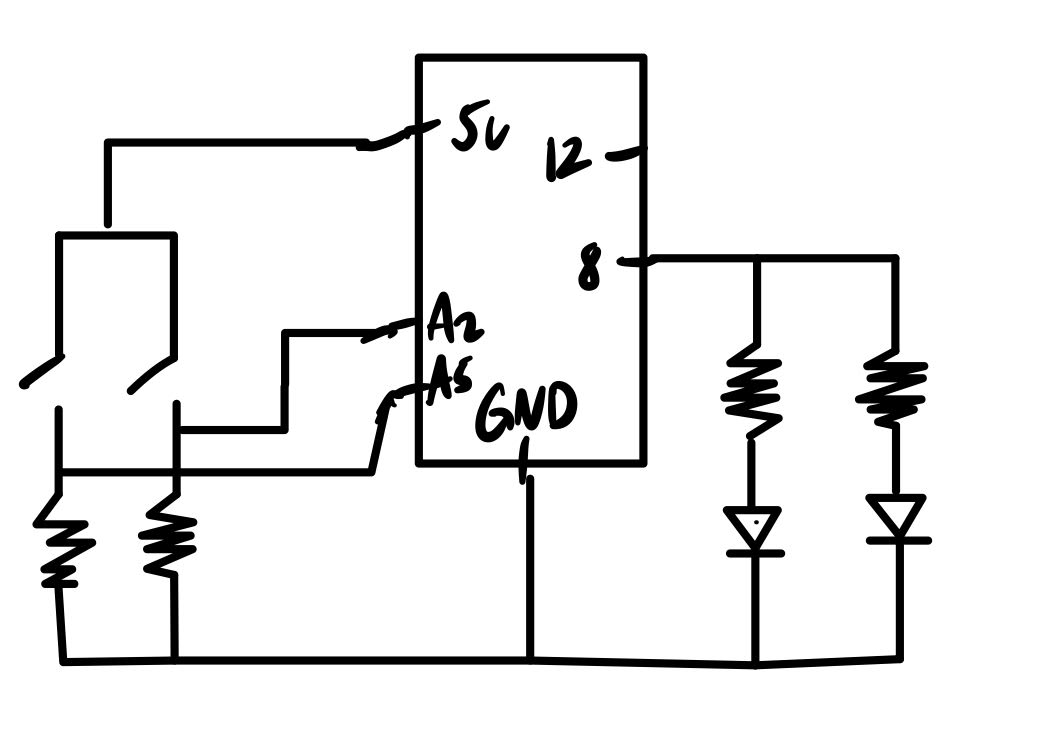
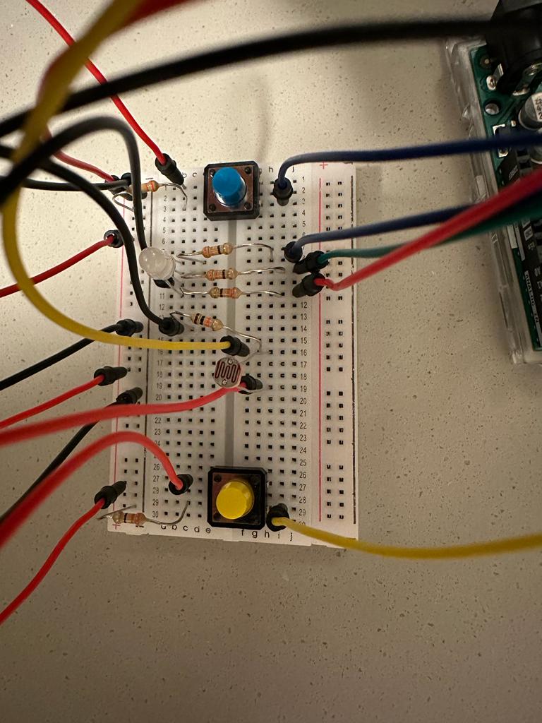
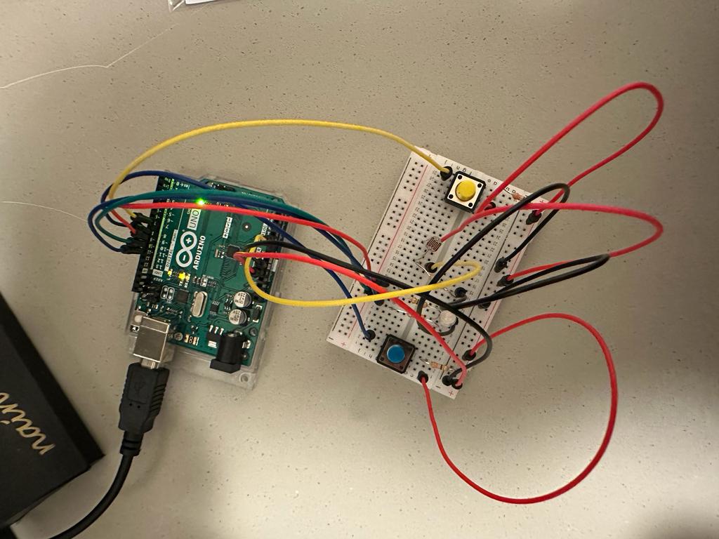
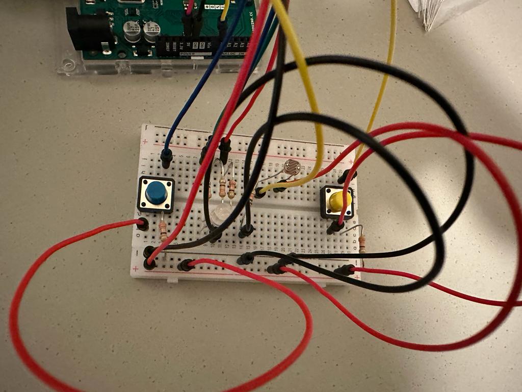
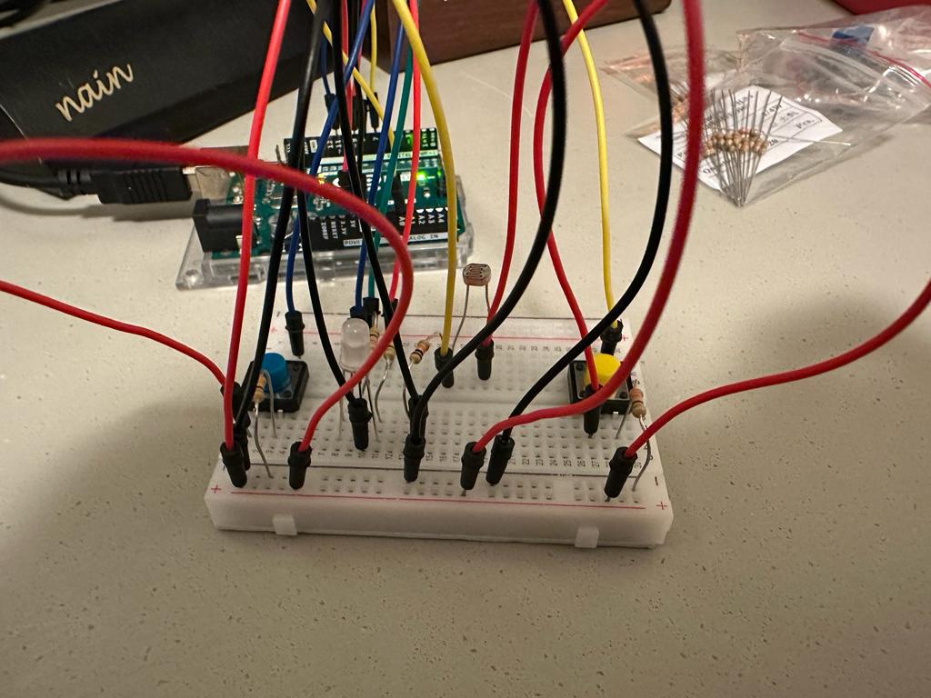
For my circuit, I had two buttons each connected to a resistor and a input slot A2 and A5 where if one of the buttons are pressed, the correlating LED light will blink in an 500 delay interval. If the button is released, then the light will stop blinking. If both of the buttons are pressed, then both lights will blink at 100 delay interval.
Initially I was trying to have the buttons as a trigger to a function that will continue in a loop so that the lights will keep blinking if I pressed the button once and will stop blinking if I pressed it again. However, since I was not so proficient with arduino yet, I failed to achieve the effect. I think this could be an improvement I could work on for future practices.
While brainstorming with my roommate about what to make for this week’s assignment, my suitemate arrived and expressed his frustration about our friends constantly knocking on our door when we’re not there. He complained about the disturbance, particularly during exams and at night. While apologizing to him, an idea popped into my head – a solution that would inform our friends about our availability. The concept involves two LEDs outside our room representing my roommate and me, which will turn on when we’re in the room and off when we’re not. If neither of us are in the room, we can press the two buttons together before leaving, causing the lights to flicker, indicating that we are not available. This solution could potentially address the problem for our friends and our suitemate.
Implementation:
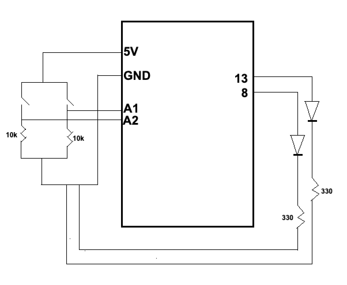
To help navigate the board, I first drew the circuit diagram so that I would know what component would go where. To make my life easier, I used the red wire for 5V, black wire for GND, green wire for the green button, yellow wire for yellow button and the two white wires for the two LEDs. The circuit diagram looks like this:
I did run into a few problems with the code where pushing the button for a relatively longer period would reverse the effect that I wanted. I then added delay in certain places to resolve this issue. The code looks like this:
//globally declaring the three variables. Setting them to 1 so that all the lights are off
int yellowCount = 1;
int greenCount = 1;
int doubleCount = 1;

void setup() {
  //setting pinmodes. 8 and 13 as output since they are connected to the LEDs
  pinMode(8, OUTPUT);
  pinMode(13, OUTPUT);
  pinMode(A2, INPUT); //A1 and A2 as input for the switches
  pinMode(A1, INPUT);
}

void loop() {
  int yellowSwitch = digitalRead(A2); //read the yellow switch
  delay(100);
  int greenSwitch = digitalRead(A1);
  delay(100);

  if (greenSwitch == HIGH && yellowSwitch == HIGH) //when both the switches are pressed together
  {
    doubleCount = doubleCount + 1; //increment this counter

  }
  else
  {
    if (yellowSwitch == HIGH) //for individual switches, increment their respective counters
    {
      yellowCount = yellowCount + 1;
    }

    if (greenSwitch == HIGH)
    {
      greenCount = greenCount + 1;
    }
  }

  if (doubleCount % 2 == 0) //if the counter is even
  {
    digitalWrite(8, HIGH);  //high for one
    digitalWrite(13, LOW); //low for the other
    delay(150); //wait
    digitalWrite(8, LOW); //then invert the voltages
    digitalWrite(13, HIGH); //to give off a flickering effect
    delay(150);

    yellowSwitch = digitalRead(A2); //read the two again
    greenSwitch = digitalRead(A1);

    if (yellowSwitch == HIGH) //if one of them is pressed
    {
      doubleCount = doubleCount + 1; //then this values goes to odd and then the flickering stops
    }

    if (greenSwitch == HIGH)
    {
      doubleCount = doubleCount + 1;
    }

  }
  else
  {
    if (yellowCount % 2 == 0) //if the yellow is pressed again and the count is even
    {
      digitalWrite(8, HIGH); //turn on the led
    }
    else
    {
      digitalWrite(8, LOW); //otherwise turn it off
    }

    if (greenCount % 2 == 0) //same for the green button
    {
      digitalWrite(13, HIGH);
    }
    else
    {
      digitalWrite(13, LOW);
    }
  }
}
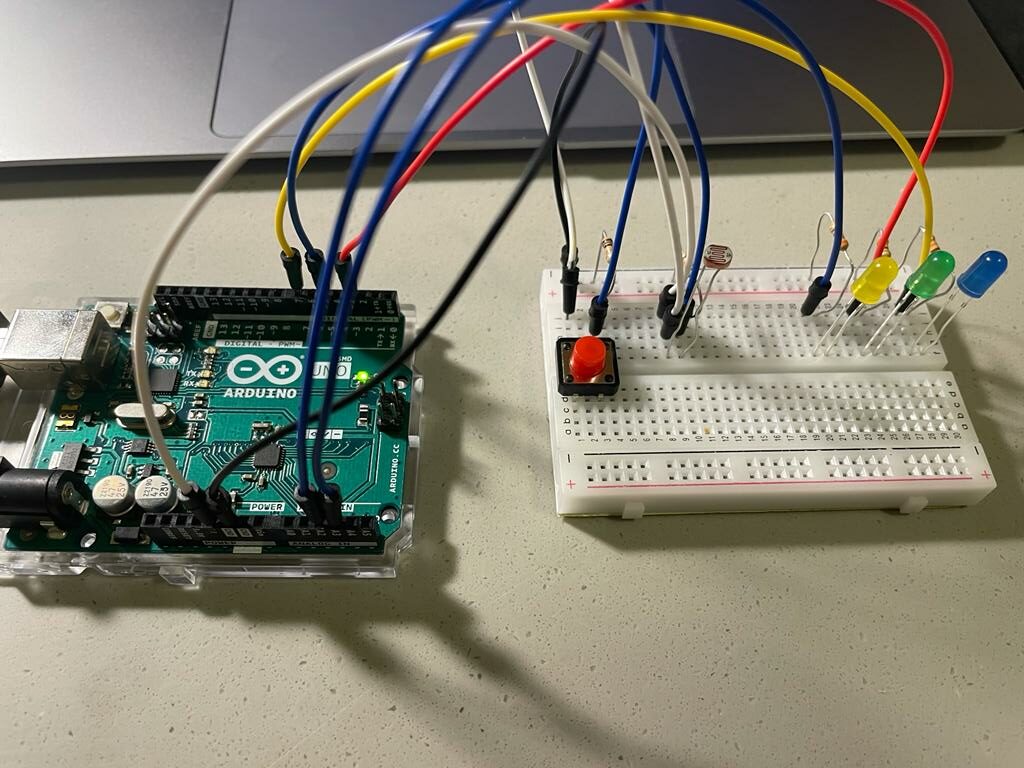
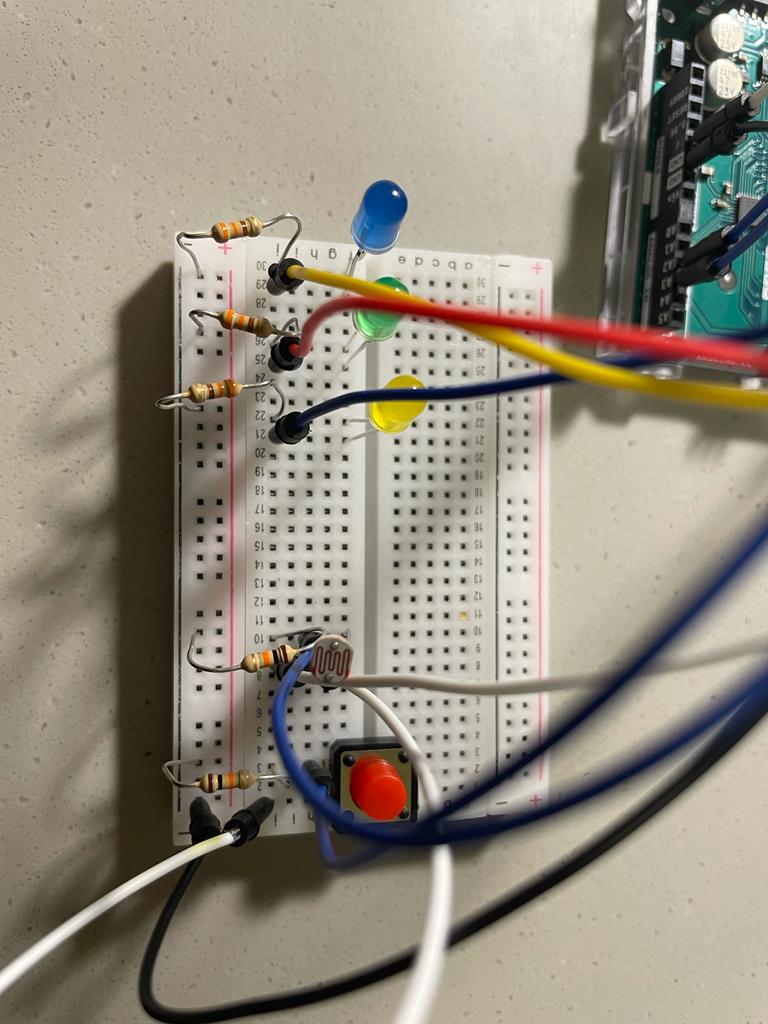
The final implementation looks like this:
Further Improvements:
Instead of LEDs, an LCD or a display could be used that would display messages as “BOTH IN ROOM”, “MOEEZ IN ROOM”, or “NONE IN ROOM” etc. Moreover, the code could use some refinement as well with the delay function. Adding a security layer such as a password using a keypad so that only me and my roommate can update it can also help increase its accuracy.
For the purpose of this Assignment we had to get information from at least one analog sensor and at least one digital sensor, and use this information to control at least two LEDs, one in a digital fashion and the other in an analog fashion, in some creative way. What can be more creative than a game?! So I decided to create a mini game using photoresistor, button and three different LEDs. The aim of the game is to try to get all the three LEDs on and catching that moment by clicking the button. If you would be able to simultaneously light up all three LEDs and press the button you won the game which will be indicated by mini disco show at the end. This game is not easy as the gamer should predict the distance of his finger from the photoresistor and find that sweet spot where all the three LED conditions for turning on are satisfied. Furthermore, player needs to use his/her reflexes to immediately click on the button.
Circuit
Implementation
The Arduino board has three LED lights, with three of them being regulated by an analog input device called a photoresistor. The photoresistor will determine the intensity of the red, blue, and yellow lights. I created a sensor value variable which is
sensorValue = analogRead(LDR);
depending on its value the different LEDs are on if the conditions are satisfies. In the case when the 700 < sensorValue < 800 and if all other if conditions are not satisfied the analogWrite is 0 for all three colors. See the code below:
For the digital interaction the led lights will be controlled by digital input, the button, and under very specific circumstances when the all three LEDs are on and the player was able to successfully catch that second and click the button the mini discoteca show at the end will depict their win. The code below if for this function:
Developing this Arduino project was an exciting and challenging experience for me. It allowed me to combine my knowledge of analog and digital sensors, LED lights, and programming to create an entertaining mini game. there are several areas where I can improve it in the future. For instance, I could incorporate a timer that counts down the seconds before the LEDs turn off, which would add an additional level of difficulty to the game. Another possible improvement would be to incorporate different levels of difficulty, such as changing the optimal distance of the player’s finger from the photoresistor or increasing the number of LEDs required to win the game. Overall, this project was a great learning experience for me, and I look forward to implementing these improvements and exploring other creative Arduino projects in the future.
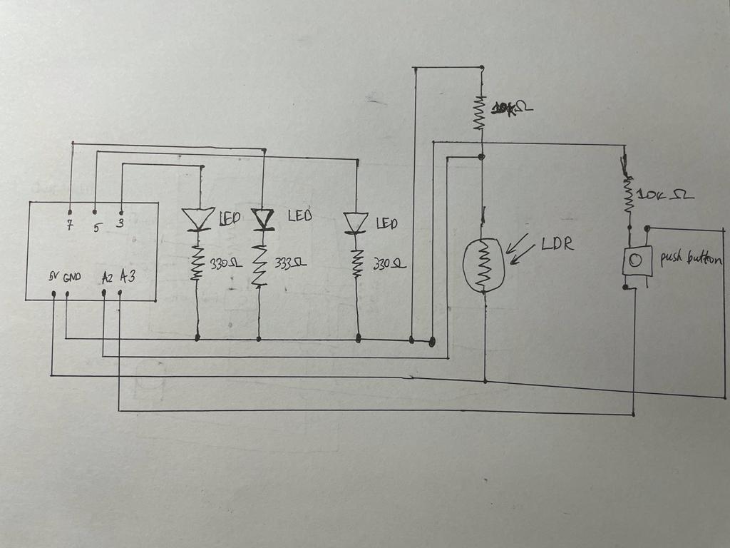
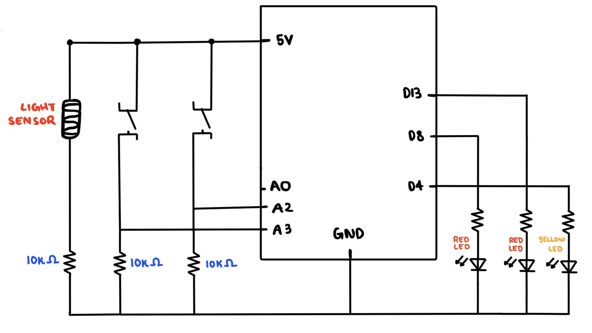
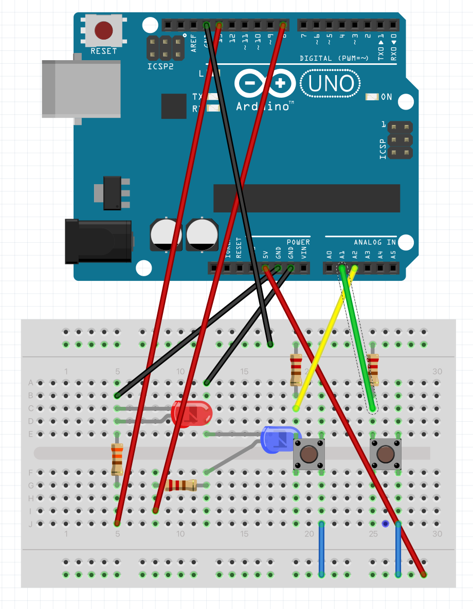
For my assignment, we were told to deal with one a digital and an analog sensor, hence for my digital sensors, I used two switches and for my analog sensors I went with the light sensor. My idea for this assignment was to mimic police siren lights because I thought it might be creative and cool.
How it would work is you have two red led lights which both have their respective switches. Hence, if you press one switch, one of the red led lights would switch on. Same case if you were to press the other switch. However, if you were to press both switches at the same time, they would blink alternatively like police siren lights.
For the light sensor, I would make it such that if the light sensor reads above some specific threshold of voltage, then it would trigger another yellow led to indicate that the light sensor has switched and this would in turn also active both the red led lights to once again alternate while blinking, mimicking that police siren light effect.
Schematic:
Arduino Code:
const int ANALOG_THRESHOLD = 500;   //Constant Threshold of light used for the Light Sensor.


void setup() {
  pinMode(13, OUTPUT);  //Top RED LED
  pinMode(8, OUTPUT);   //Bottom RED LED
  pinMode(4, OUTPUT);   //YELLOW LED
  pinMode(A2, INPUT);   //Switch 1 (Bottom Switch)
  pinMode(A3, INPUT);   //Switch 2 (Top Switch)
  pinMode(A0, INPUT);   //Analog Reader for Light Sensor
}

void loop() {
  int analogValue = analogRead(A0);
  int switch1 = digitalRead(A2);
  int switch2 = digitalRead(A3);

  //If the bottom switch is on, then the bottom light will be on (LED connected to pin-8).
  //Otherwise, it will remain off.
  if(switch1 == HIGH) {
    digitalWrite(8, HIGH);
  } else {
    digitalWrite(8, LOW);
  }

  //If the top switch is on, then the top light will be on (LED connected to pin-13).
  //Otherwise, it will remain off.
  if(switch2 == HIGH) {
    digitalWrite(13, HIGH);
  } else {
    digitalWrite(13, LOW);
  }

  //If both switches are pressed together, then it will call the police_siren() function:
  if(switch1 == HIGH && switch2 == HIGH) {
    police_siren();
  }

  //Above all else, the switches will remain off if neither of the switches are pressed
  else {
    digitalWrite(13, LOW);
    digitalWrite(8, LOW);
  }


  //This is for the light sensor, if the analogValue read from A0 is greater than the threshold value of light.
  //Then it would let the yellow LED turn on and signal to call the police_siren() function.
  if(analogValue > ANALOG_THRESHOLD) {
    digitalWrite(4, HIGH);
    police_siren();
  }

  //If the analogValue read is below the threshold of light, then it will remain off.
  else {
    digitalWrite(4, LOW);
  }
}

//This is the police_siren function which simply takes the two RED LEDS and blinks them alternatively.
//Essentially mimicking a police siren lighting on top of a police car.
void police_siren() {
    digitalWrite(13, LOW);
    digitalWrite(8, HIGH);
    delay(300);
    digitalWrite(13, HIGH);
    digitalWrite(8, LOW);
    delay(300);
}
Imagine you’re in a dark room, and you have two switches in front of you. Each switch corresponds to a color: red and blue. You flip the switch for the red LED, and suddenly, the room is bathed in a warm, red glow. But then you start to wonder: what would happen if you flipped the blue switch too? Would the room turn purple? Would the colors clash or blend together in harmony?
That’s where this code comes in. With just a few lines of code, you can experiment with different combinations of red and blue light and create a range of beautiful color schemes. The code uses analogWrite() to control the brightness of the LEDs, allowing you to create smooth transitions between different levels of light intensity.
But it’s not just about the colors themselves. The code also uses if statements to detect when both switches are flipped at the same time, triggering a unique effect where both LEDs fade in and out together. This creates a mesmerizing effect that can be calming, energizing, or just plain fun to watch.
This code offers a simple and fun way to experiment with LED lighting effects and can be easily customized to create new and unique patterns. For example, you could add more LEDs and switches, or modify the fade amount and brightness values to create different effects. The possibilities are endless!
Circuit
Code
// Define the pin numbers for the red and blue LEDs
int redLedPin = 9;
int blueLedPin = 11;

// Define the fade amount and initial brightness for the LEDs
int fadeAmount = 50;
int redBrightness = 0;
int blueBrightness = 0;

void setup() {
  // Set the pin modes for the switches and LEDs
  pinMode(A1, INPUT);
  pinMode(A2, INPUT);
  pinMode(redLedPin, OUTPUT);
  pinMode(blueLedPin, OUTPUT);
}

void loop() {
  // Read the digital input values of the switches
  int switchPositionRed = digitalRead(A2);
  int switchPositionBlue = digitalRead(A1);

  // If the switch for the red LED is pressed, turn on the red LED and turn off the blue LED
  if (switchPositionRed == HIGH) {
    digitalWrite(redLedPin, HIGH);
    digitalWrite(blueLedPin, LOW);
  }
  // If the switch for the blue LED is pressed, turn on the blue LED and turn off the red LED
  else if (switchPositionBlue == HIGH) {
    digitalWrite(redLedPin, LOW);
    digitalWrite(blueLedPin, HIGH);
  }
  // If neither switch is pressed, turn off both LEDs
  else {
    digitalWrite(redLedPin, LOW);
    digitalWrite(blueLedPin, LOW);
  }

  // If both switches are pressed, fade both LEDs in and out
  if (switchPositionRed == HIGH && switchPositionBlue == HIGH){
    // Set the brightness of the red LED and increase/decrease it by the fade amount
    analogWrite(redLedPin, redBrightness);
    redBrightness += fadeAmount;
    if (redBrightness == 0 || redBrightness == 255) {
      // Reverse the fade direction when the brightness reaches 0 or 255
      fadeAmount = -fadeAmount;
    }

    // Set the brightness of the blue LED and increase/decrease it by the fade amount
    analogWrite(blueLedPin, blueBrightness);
    blueBrightness += fadeAmount;
    if (blueBrightness == 0 || blueBrightness == 255) {
      // Reverse the fade direction when the brightness reaches 0 or 255
      fadeAmount = -fadeAmount;
    }
    // Delay for a short amount of time to create the fading effect
  delay(800);
  }


}
As part of the 6th Assignment of Intro to IM, we were tasked with the objective of reading input from at least one analog sensor, and at least one digital sensor (switch). This data would then be used to control at least two LEDs, one in a digital fashion and the other in an analog fashion, in some creative way.
I have always had a great emphasis on the ‘lighting’ around me, and therefore am fond of purchasing different lamps and setting them up to have a good ambiance. This brings me to an interesting lamp I saw once at the convenience store, called Mood Lamp. If you are not aware of what those are, the following video should help you get an idea of it:
Therefore, being inspired from the concept of a ‘switching’ light and wanting to add some additional functionality to it, I decided to test my Arduino and Circuit Making skills to implement a model Mood Lamp. The concept was to use the button or switch as the digital sensor and the light sensor as the analog sensor (controlled by another button) which modifies the brightness of the light. The primary button would be used to modify the color modes of the LED, and a secondary button would toggle the brightness functionality of the light sensor.
Implementation
Pictures of Circuit
With this, I produced the following circuit:
Demo Video
A demo video, in detail, can be seen here:
The implementation of the Mood Lamp on the breadboard can be seen above. To make it clear, since the quality of Video did not allow the RGB LED Bulb to be captured to perfection, the Switch on the right, Yellow colored, is used to switch between the different modes of light. In our case, the modes are: Switched Off, Rainbow (Fading), Blue, Green, and Red. Alongside this, the blue button on the left, toggles the brightness adjustment option by making use of the light sensor. The meaning of this is, if the light in the room is brighter, the bulb will glow brighter, and if the light is less, it will grow lighter. Since it is a mood lamp, usually used at night, the purpose of it is to adapt with the light. At night, it should automatically adapt to the surrounding light to make its own light visible.
Code
Since the Code cannot be linked with Arduino, unlike P5js, I will be pasting the entire code here for anyone’s reference!
// Declaration of Constants
const int BUTTON_PIN_LIGHT = 7;  // Connecting the Light Button to Pin 7
const int BUTTON_PIN_LDR = 8;  // Connecting the Photoresistor Button to Pin 7
const int PIN_RED   = 9; //Red LED connected on pin 9
const int PIN_GREEN = 10; //Green LED connected on pin 10
const int PIN_BLUE  = 11; //Blue LED connected on Pin 11
const int LIGHT_SENSOR_PIN = A0; // Connecting the Photoresistor to Pin A0

//Color intensities and direction
//Initial Values for the Fading Rainbow Color Mode
int red             = 254;
int green           = 1;
int blue            = 117;
int red_direction   = -1;
int green_direction = 1;
int blue_direction  = -1;

// Function to set the color of the RGB LED
void setColor(int R, int G, int B) {
  analogWrite(PIN_RED,   R);
  analogWrite(PIN_GREEN, G);
  analogWrite(PIN_BLUE,  B);
}

// Declaration of changing variables
int ledState = 1; // tracks the current state of LED
int ldrState = 1; // tracks the current state of LED
int lastlightButtonState; // the previous state of the light button
int currentlightButtonState; // the current state of the light button
int lastLDRButtonState; // the previous state of the ldr button
int currentLDRButtonState; // the current state of the ldr button
int analogValue; // tracks the light intensity from the LDR
int brightness; // tracks the brightness extracted from the analog Input

void setup() {
  Serial.begin(9600);
  // Settings the Inputs and Outputs of the previously specified pins
  pinMode(BUTTON_PIN_LIGHT, INPUT);
  pinMode(PIN_RED,   OUTPUT);
  pinMode(PIN_GREEN, OUTPUT);
  pinMode(PIN_BLUE,  OUTPUT);
  // Detect initial values of the buttons
  currentlightButtonState = digitalRead(BUTTON_PIN_LIGHT);
  currentLDRButtonState = digitalRead(BUTTON_PIN_LDR);
}

void loop() {
  lastlightButtonState  = currentlightButtonState; // Store Previous State of the light button
  currentlightButtonState = digitalRead(BUTTON_PIN_LIGHT); // Get new state of the light button
  // Same for the LDR Button
  lastLDRButtonState  = currentLDRButtonState;
  currentLDRButtonState = digitalRead(BUTTON_PIN_LDR);

  // Gets the Analog Value from the LDR Sensor
  Serial.print("Light Sensor Value: ");
  analogValue = analogRead(LIGHT_SENSOR_PIN); // read the input on analog pin
  Serial.println(analogValue);

  // Detects if there has been a change in the state of the switch - if it has been pressed
  if(lastLDRButtonState == HIGH && currentLDRButtonState == LOW) {
    Serial.println("LDR (Blue) Button is pressed: ");
    // Change state of LDR Switch
    if(ldrState == LOW) {
       ldrState = HIGH;
       Serial.println("Turning Brightness Variation on");
    }
    else {
      ldrState = LOW;
      Serial.println("Turning Brightness Variation off");
    }
  }

  if (ldrState==HIGH){  // If the Brightness option has been switched on
    brightness = map(analogValue, 0,1023, 0, 255);
  }
  else{ // Otherwise
    brightness = 255;
  }

  // If the light button has been toggled
  if(lastlightButtonState == HIGH && currentlightButtonState == LOW) {
    Serial.print("Light (Yellow) Button is pressed: ");

    Serial.println(ledState);

    // Change the state of LED
    if(ledState == 0) {
       ledState = 1;
       setColor(0, 0, 0); //set LED to Off
    }
    else if (ledState == 1){
      ledState = 2;
      Serial.println("Turning LED Rainbow");
    }
    else if (ledState == 2){
      ledState = 3;
      Serial.println("Turning LED Blue");
    }
    else if (ledState == 3){
      ledState = 4;
      Serial.println("Turning LED Green");
    }
    else{
      ledState = 0;
      Serial.println("Turning LED Red");
    }
  }
  // Changing the colors of the LEDs depending on the State they should be in
  if (ledState == 2){
      red = red + red_direction;
      green = green + green_direction;
      blue = blue + blue_direction;

      // Change direction for each color if it reaches 255
      if (red >= brightness || red <= 0)
      {
        red_direction = red_direction * -1;
      }
      if (green >= brightness || green <= 0)
      {
        green_direction = green_direction * -1;
      }
      if (blue >= brightness || blue <= 0)
      {
        blue_direction = blue_direction * -1;
      }
      setColor(red, green, blue);
  }
  else if (ledState == 3){
    setColor(0, 0, brightness); //set LED to Blue
  }
  else if (ledState == 4){
    setColor(0, brightness, 0); //set LED to Green
  }
  else if (ledState == 0){
    setColor(brightness, 0, 0); //set LED to Red
  }
}

// References taken from:
// https://www.thegeekpub.com/277872/arduino-rgb-led-tutorial/
// https://www.thegeekpub.com/275412/use-a-button-to-toggle-an-led-arduino-tutorial/
// https://www.thegeekpub.com/275412/use-a-button-to-toggle-an-led-arduino-tutorial/
The code is making use of complex state machines, particularly the ledState, and even the ldrState. These states are toggled with the pressing of buttons, and then ultimately control the modifications to other values
Difficulties & Improvements
As I am controlling the brightness, in the RGB LED, I was able to control the brightness when each individual light was switched on only itself with some discrete value. However, as the values fluctuated for the Rainbow mode, the implementation of the Brightness option did not go as planned:
if (ledState == 2){
    red = red + red_direction;
    green = green + green_direction;
    blue = blue + blue_direction;

    // Change direction for each color if it reaches 255
    if (red >= brightness || red <= 0)
    {
      red_direction = red_direction * -1;
    }
    if (green >= brightness || green <= 0)
    {
      green_direction = green_direction * -1;
    }
    if (blue >= brightness || blue <= 0)
    {
      blue_direction = blue_direction * -1;
    }
    setColor(red, green, blue);
}
As shown above, I have tried to set the maximum values as the brightness, however, since the values are changing very fast, there is some issue with the brightness not being adjusted with the above code. I have tried to implement the usage of MOD, like red%brightness, but that has resulted in no effort either!
For this weeks homework I decided to continue my work from class and make use of the switch for the digital sensor and the light sensor for the analog one.
I decided to do quite a simple light attached to the switch, when the switch is on the light is on, when you are no longer pressing the switch, the light goes off.
Here is the simple code:
// read the input on digital pin 2:
int buttonState = digitalRead(pushButton);

// if switch is on, turn LED on
if(buttonState==1) {
  digitalWrite(8, HIGH);
}
// if switch is off, turn LED off
else {
  digitalWrite(8, LOW);
}
For the analog sensor, I wanted to do a light dimmer where the dimness corresponds to the dimness that the sensor catches. This required a bit of math and a few if statements, because it is hard to achieve very low values with a light sensor, and unless the values are very low, the LED is quite bright.
Here is the code for that below:
// read the input on analog pin A2:
float sensorValue = analogRead(A2);

// exponential value for analogLEDValue
int analogLEDValue = 25.5*pow(10,(sensorValue/950));

// some more tweaking to get a more drastic change in output
if(analogLEDValue<200) {
  analogLEDValue=analogLEDValue/2-50;
}
else if(analogLEDValue<150) {
  analogLEDValue=analogLEDValue/4-50;
}
// control so it does not go <0
if(analogLEDValue<0){
  analogLEDValue=0;
}

// output
analogWrite(6, analogLEDValue);
The idea of this work was inspired by the car parking sensor. While parking your car starts playing a sound that gets louder the closer you get to an object. Likewise in my Arduino the close you get to the object the “Redder” the RGB LED light becomes. The farther you are from the object, the sensor becomes a blueish color. This way you can visually measure the distance between you and an object.
The ultrasonic sensor measures the time taken to get the response back from the object, which I later converted into the distance. RGB LED light displays the color based on the distance calculated before. A switch turns on the whole program when pressed. To display, the program works a green LED light lights on when the switch is pressed.
This snippet of the code is the main logic of the program. Quite simple. If the button is pressed then display the distance by showing Red and Blue colors. Otherwise, turn them to zero, and the green Led light to Low value.
In the future, I would like to add the sound just like in the car. This will allow measuring distance without looking anywhere. Also, a cool idea would be added to connect a projector to Arduino that displays an image stating “Stop! Too close” or “It’s ok. Go farther”. It would definitely look cool 🙂
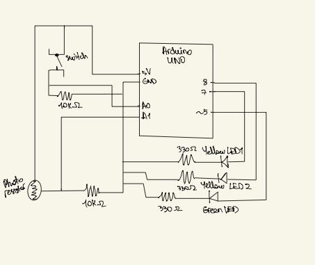
My concept for this homework was inspired by the “Oasis” project which imitates a robotic flower that blooms only at night. For my project, I decided to create a”Sunlight” meter for the plants that warns when there’s not enough light around to conduct photosynthesis, and provides a solution in the form of an artificial “sunlight. I use a light sensor as an analog sensor to measure the “sunlight”, and if it will be below the standard brightness threshold needed for photosynthesis, there will be a RED warning light coming from a blinking red LED. Also, I’m also using a switch and two other yellow LEDs. Yellow LEDs are placed around the light sensor to imitate artificial sunlight such that when the user presses the switch (i.e. when there’s not enough light around for the plant to perform photosynthesis), those two yellow LEDs will light up and will provide artificial sunlight for the plant. P.S. I am not using anything to indicate a plant in this project as I don’t have any plant in my room, but this arduino board can be placed near any plant easily tom measure the light around.
Video Demonstration
Circuit
Code
const int threshold = 150; //threshold for turning on the warning

void setup()
{
  Serial.begin(9600);
     pinMode(5,OUTPUT); //LED that signals the warning

     pinMode(7,OUTPUT); //light LED 1
     pinMode(8,OUTPUT); //light LED 2

     pinMode(A0,INPUT); //switch
     pinMode(A1,INPUT); //light sensor

}
void loop()
{
    //reading analog voltage from the light sensor and storing it in an integer
    int sensorValue  = analogRead(1);

    //scale sensorValue, which is btw 0 to 1023, to values btw 0 to 255 form analogWrite funtion which only receives  values btw this range
    int brightness = map(sensorValue, 0, 1023, 0, 255);

    //if the light sensor's brightness value will be less than threshold value
    if(brightness < threshold){

      //make the warning red LED blink
      digitalWrite(5, HIGH);
      delay(500);
      digitalWrite(5, LOW);
      delay(500);

    } else{
      digitalWrite(5, LOW);
    }

  //switch will be a digital sensor
  int switchPosition = digitalRead(A0);

  //when the switch will be pressed, two yellow LEDs surrounding the light sensor will light up, imitating a sunlight
  if (switchPosition == HIGH) {
    digitalWrite(7, HIGH);
    digitalWrite(8, HIGH);
  }
  else {
    digitalWrite(7, LOW);
    digitalWrite(8, LOW);

  }
}
The circuit is meant to represent a form of smart plant watering system. The light sensor is meant to detect the level of hypothetical sunlight, and the switch is meant to be pressed when the hypothetical soil is dried out. When the switch is held down, there is a third LED that shows that the plants are being watered, and the brightness of this LED slowly fades out, representing that the plants have been sufficiently watered. The initial brightness of this LED is based on the reading from the light sensor, to portray that you will have to water less if the sunlight isn’t as strong. Also, if the switch isn’t held down until this LED completely fades out, it will stay on to show that more watering still needs to be down.
The circuit
The circuit consists of a light sensor hooked to the Yellow LED, and the brightness of this LED is mapped to the reading from the light sensor
I realized even if I fully covered the light sensor with my hand, the reading would still be around 350-400. Thus, instead of directly mapping the input from the sensor to the output for the LED brightness, I set a threshold at 400 and below, which means that at 400 I want the light to be off, as this is a negligible amount of light.
The circuit then consists of a switch hooked to the Green LED to represent whether or not the switch is held down. This LED is digital and simply turns on and off.
There is also a third Blue LED, and this is an analog LED that is impacted by both the light sensor and the switch. The LED’s brightness is determined by the variable waterLevel, and this waterLevel is slowly decremented while the switch is pressed down.