my idea: an imagine play interactive recipe.
current progress:
-
-
-
- The basic structure is built
- the communication between Arduino and p5js is done (all the information is sent back and forth as needed
- The sensors and Arduino parts have been tested
- An instructions page that uses all the sensors has been implemented(this is demonstrated later)
Arduino and Code
Data sent and received
Arduino would send the potentiometer, force sensor, tilt sensor, ultrasonic sensor, button, and limit switch data. The P5js would get that data and use it within the interactive recipe. p5js will also send whether the oven is on or off to the arduino so that it can turn the oven LED on.
force sensor – detect mixing motion
tilt sensor – detect pouring
ultrasonic sensor – detect person picking up ingredients
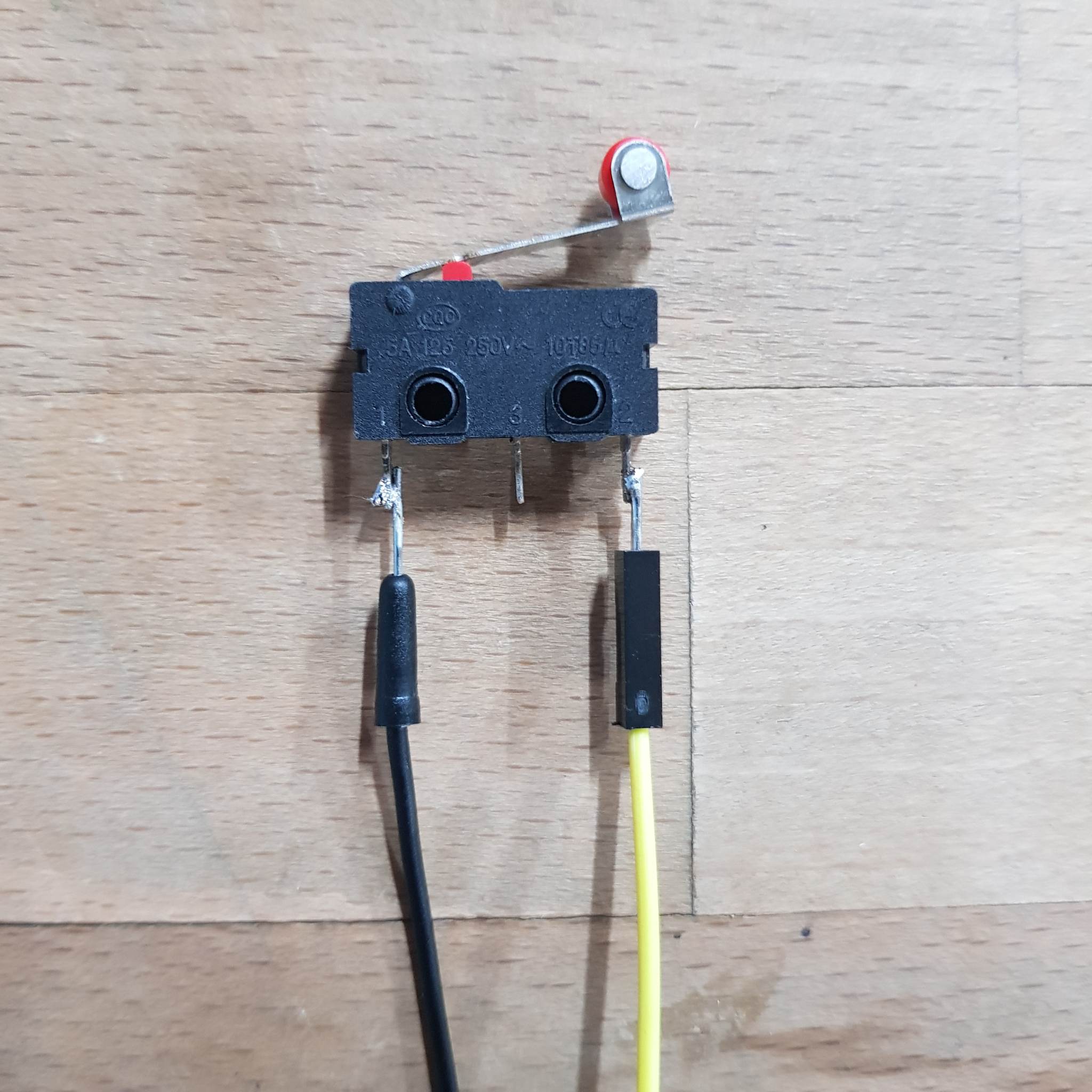
limit switch – to detect the oven door opening and closing
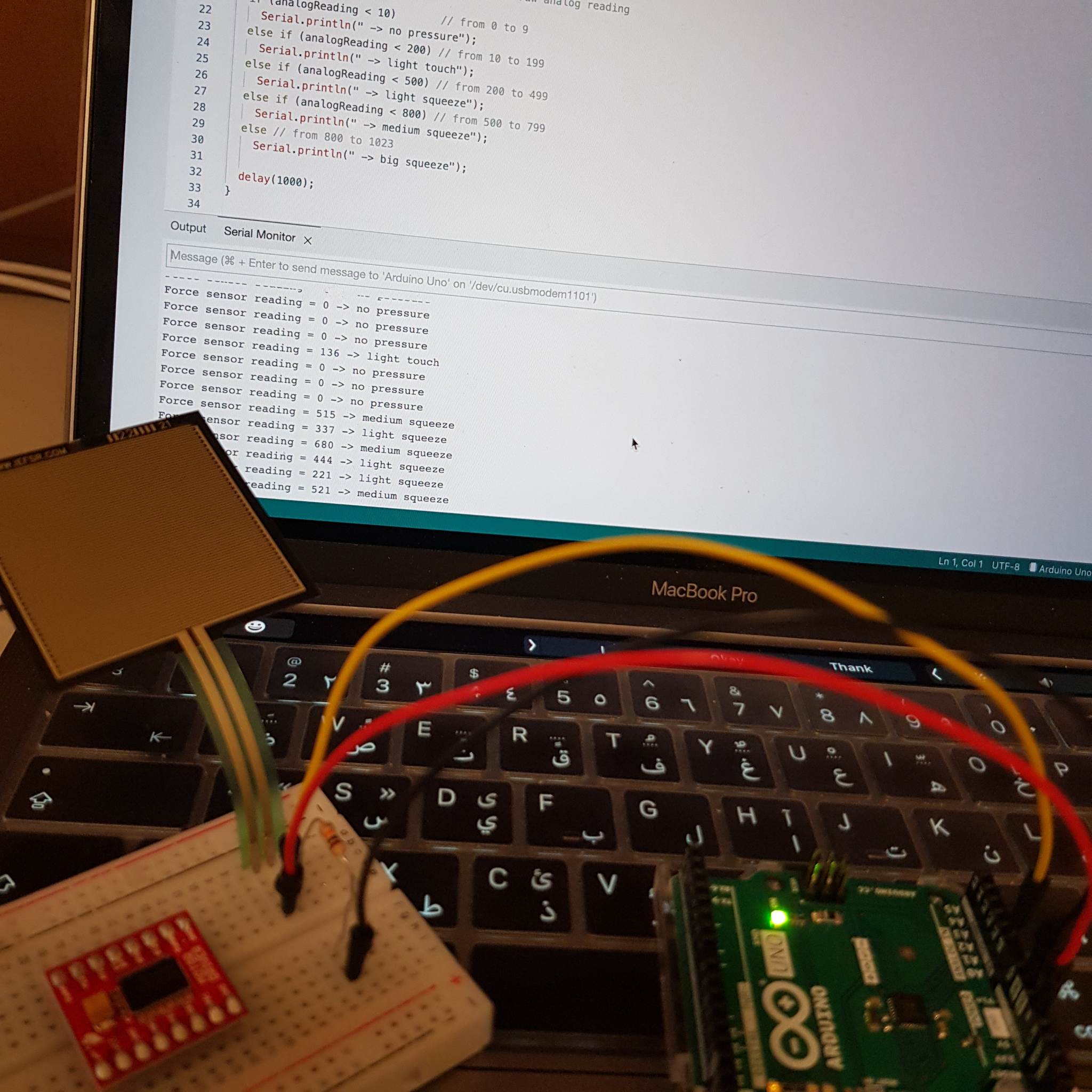
Testing sensors
I tested that the sensors did what I needed them to do.
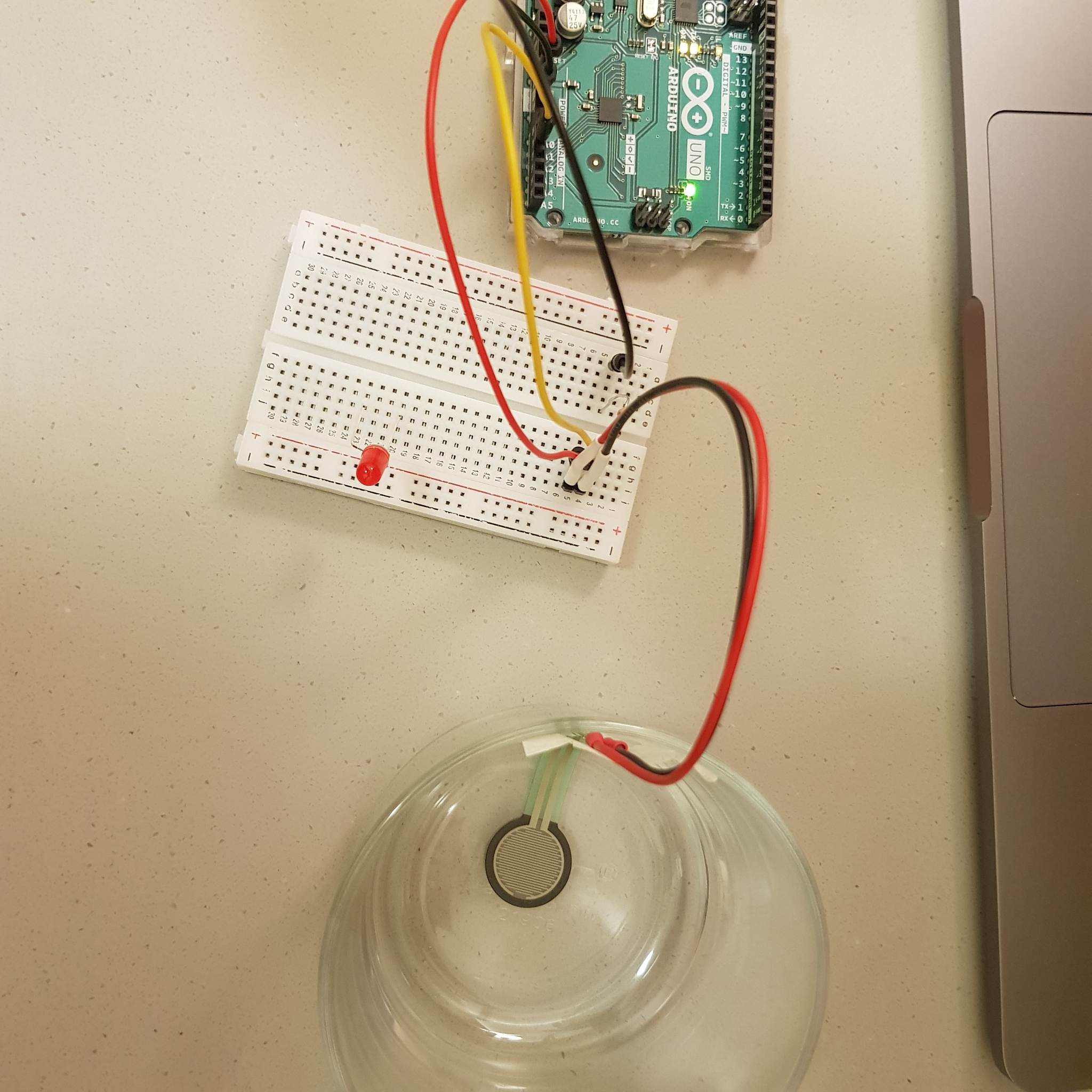
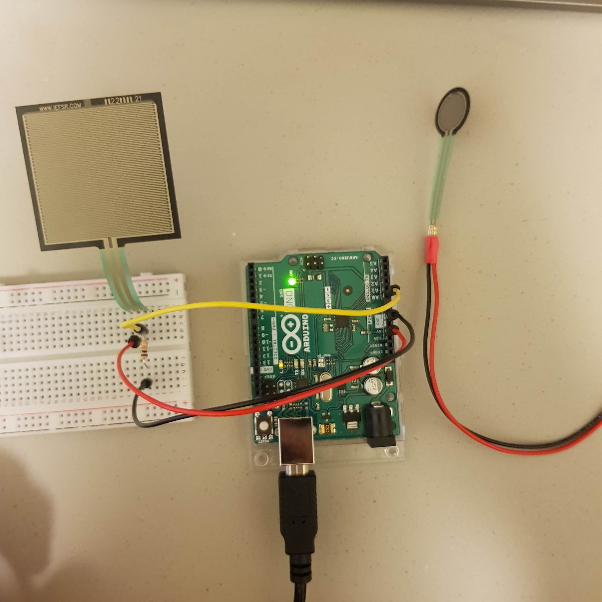
I tried the force sensor and decided to use the square one but did the initial testing with the circle one because it was already soldered.
I also tested 2 tilt sensors(I’m not entirely sure what the difference between them is, but the first fit the use better fit my project in terms of it being easier to place on the prop).
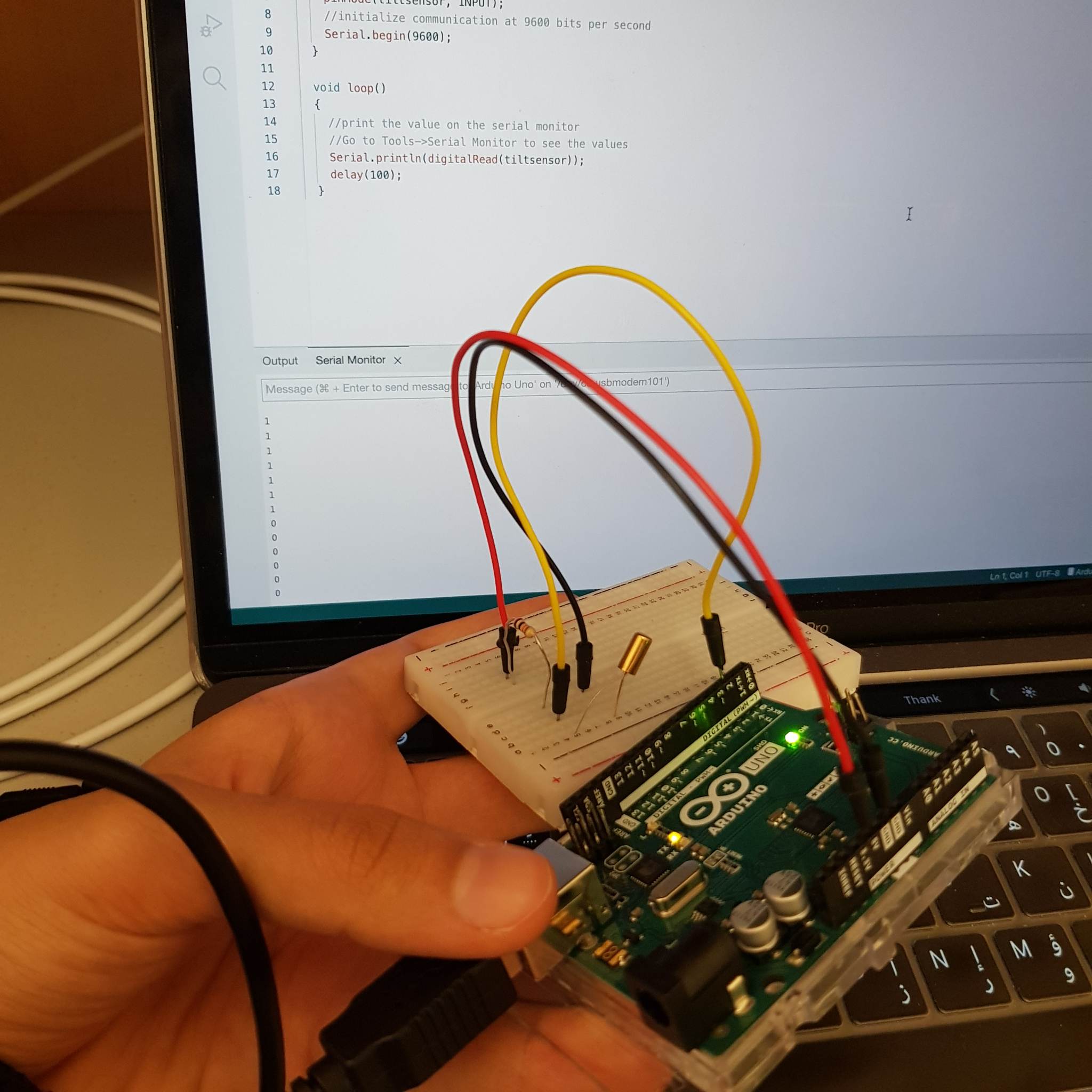
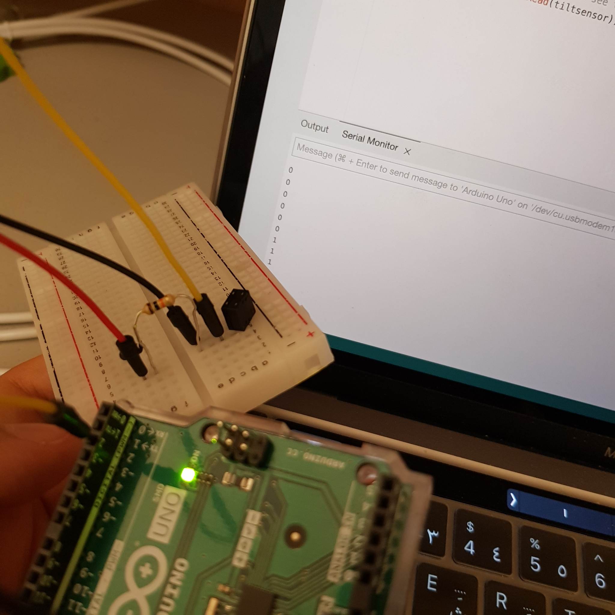
then I tried to mimic how they would be used in the project. They seemed to work as intended. I implemented a simple p5js interface that displayed wether the sensor is triggered or not.
When I tried to add the ultrasonic sensor I couldn’t send the data to p5js. I checked that the ultrasonic sensor code works on it’s own and it did. I also checked that p5js was being sent a value and it was, except that value was always 0. I looked through the code line by line and realized that the pins I was using for the Ultrasonic sensor we’re being assigned as an output (but we’re never used as output, I think they we’re part of the initial code to test something but I never removed them). I removed this, and it worked.
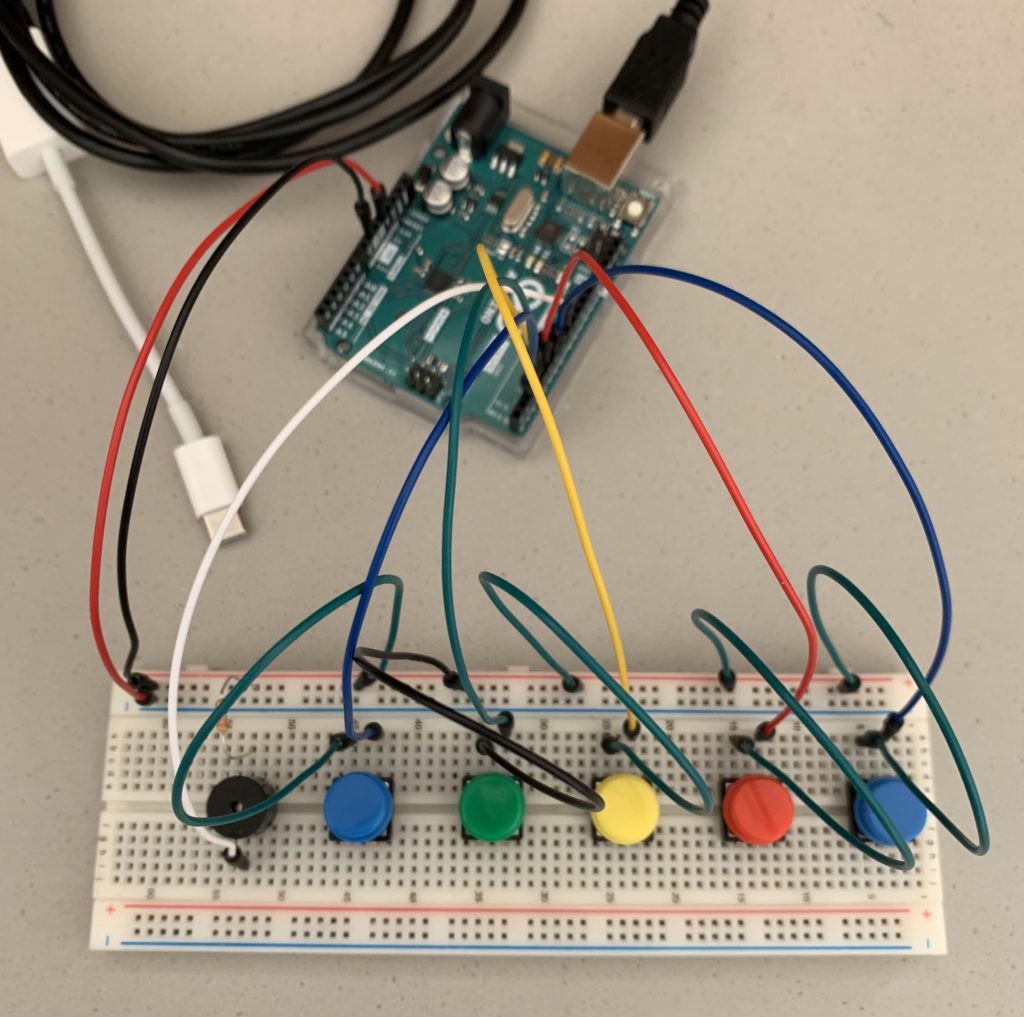
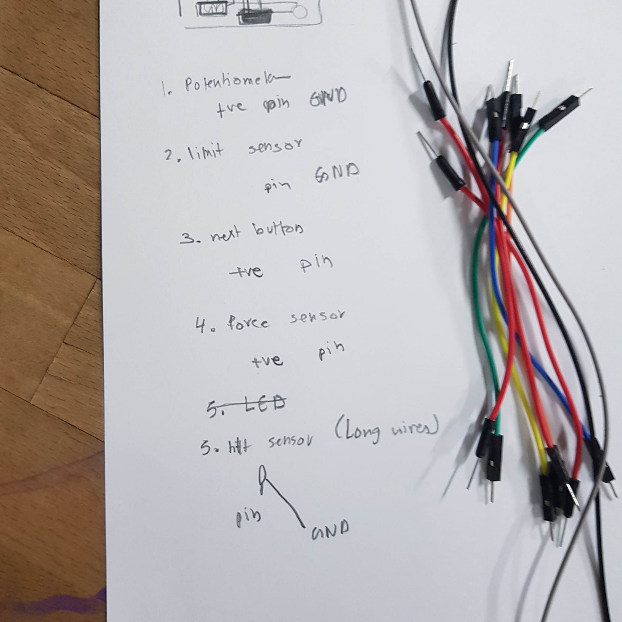
Arduino assembly
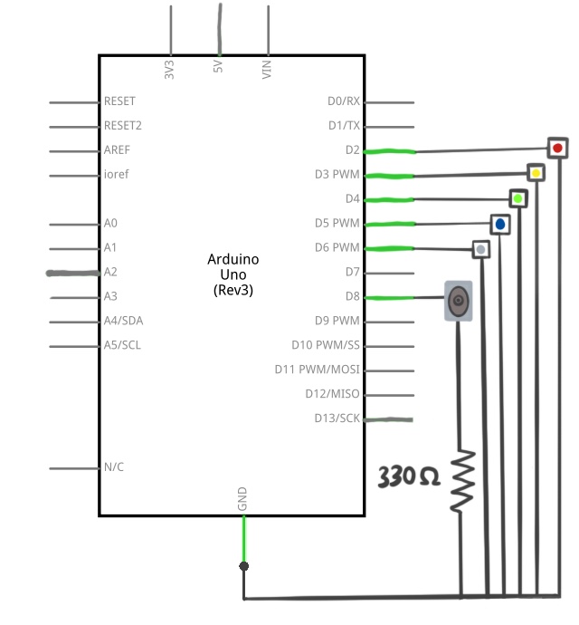
I started with noting down the wires that need to be connected to each Arduino object so that the wire colors reflect that. (I did change a few wires later on, but those pictures were taken before that so they don’t reflect the changes)
I soldered the wires to the Arduino objects. (I used jumper wires to make the process quicker)
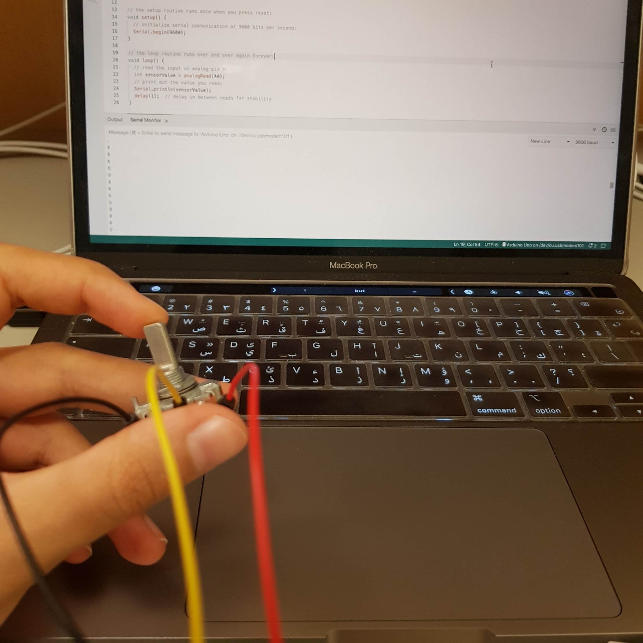
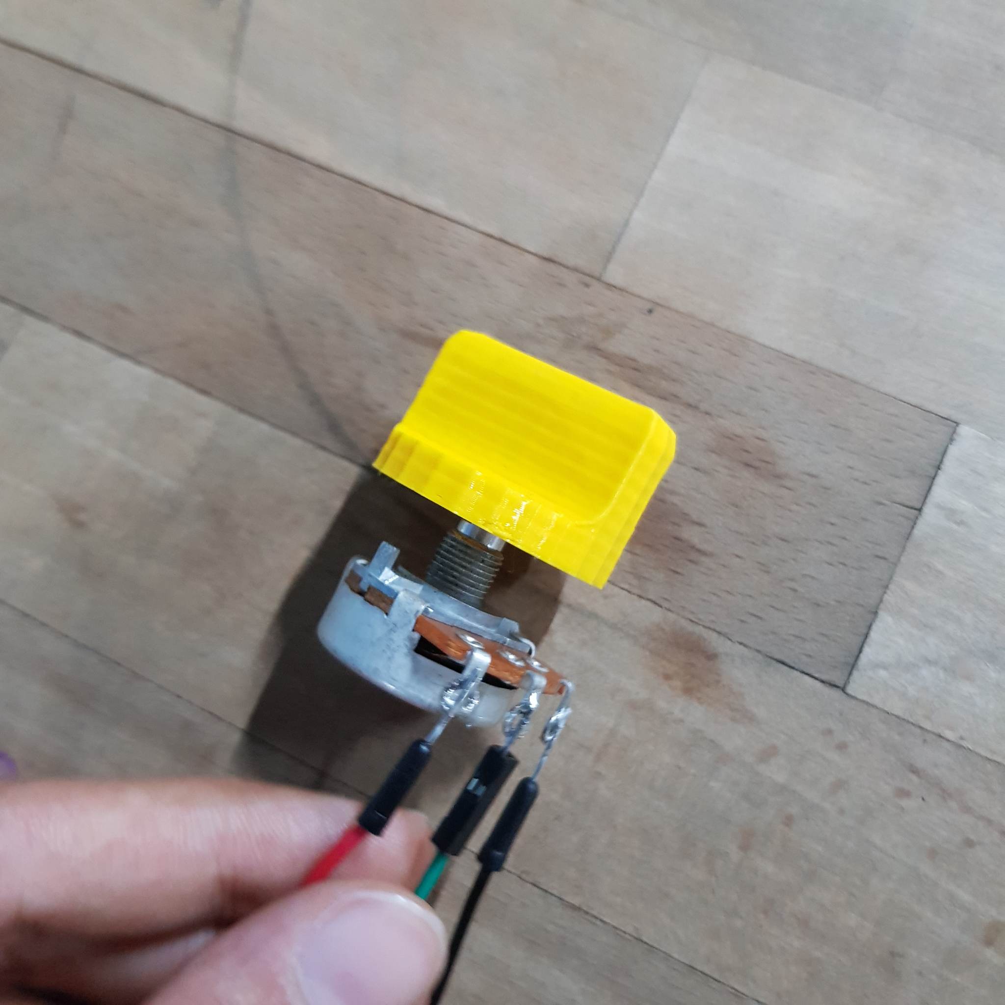
I 3D printed a knob to attach to the potentiometer.
I retested all the Arduino components together with the instructions p5js page.
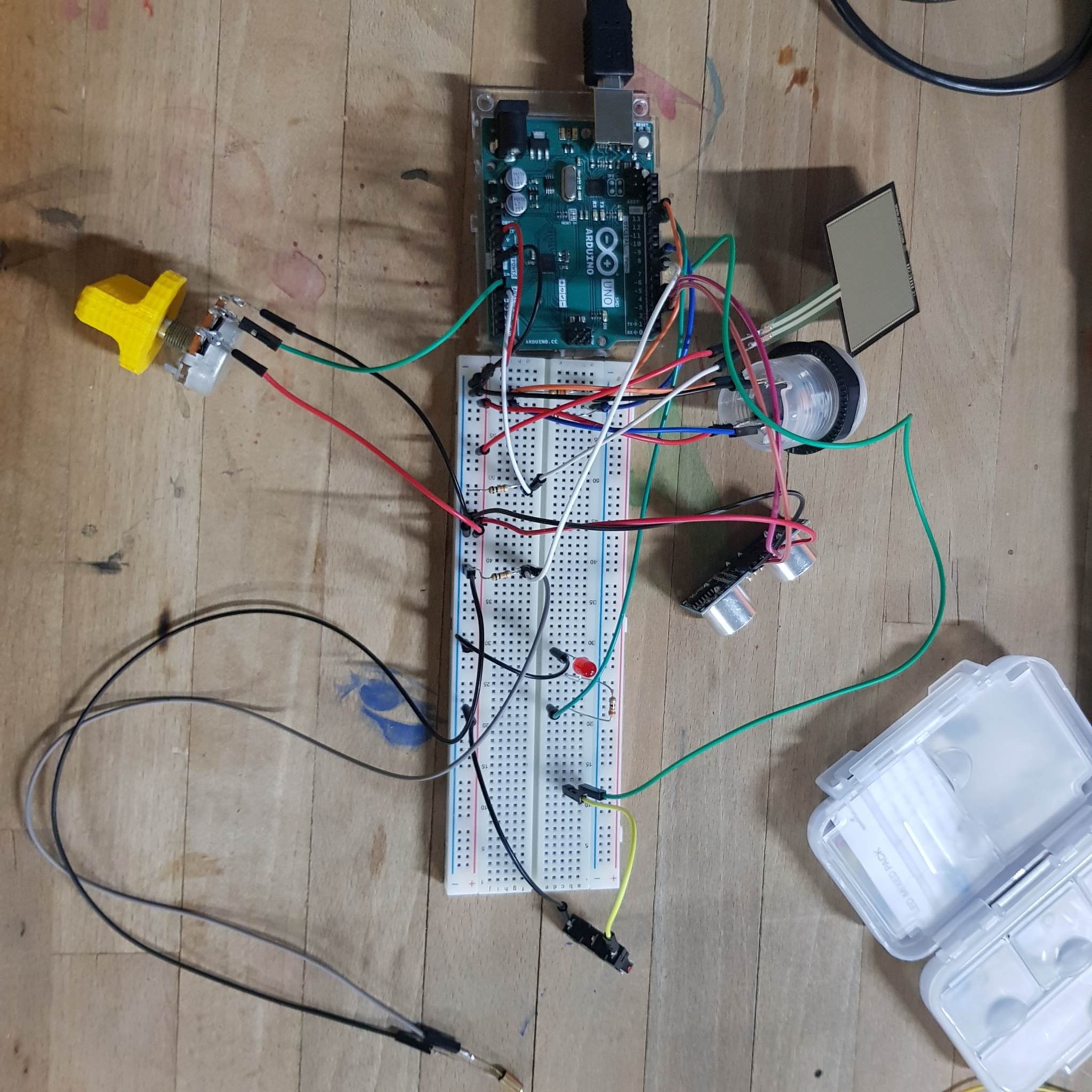
The bread board looks a bit messy but I tried to keep all the components as neat as possible and ended up moving things around a bit later to make it neater.
also, the tilt sensor was not giving a constant value and kept moving between 1 and 0 when tilted, I realized that I wired the sensor the wrong way and forgot to add a resistor
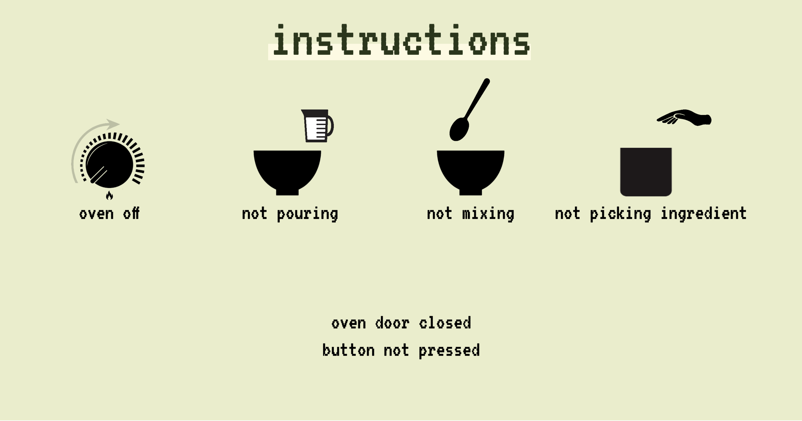
Instructions page
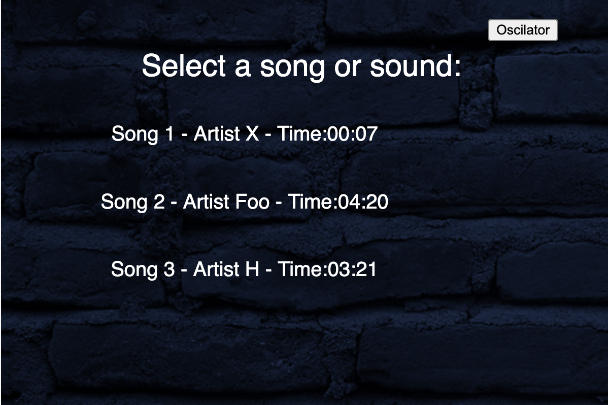
I started with the instructions page because it would utilise all the Arduino functionalities which helps with the testing and would make the future pages easier to implement. The instructions page would have all the controls and allow the user to test them out to understand how to interact with the project. I thought that this way might be a better way to familiarize the user with the game controls, compared to only having text.
Here is how the screen looks like and the images change if the user interacts with the Arduino components.
building the physical structure
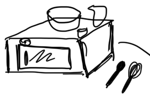
planning
I started to brainstorm the basic structure and decided that the main structure would be an oven with a door and a mixing bowl, a small container and a measuring cup on top. I also wanted to have a small compartment that would have the Arduino components.
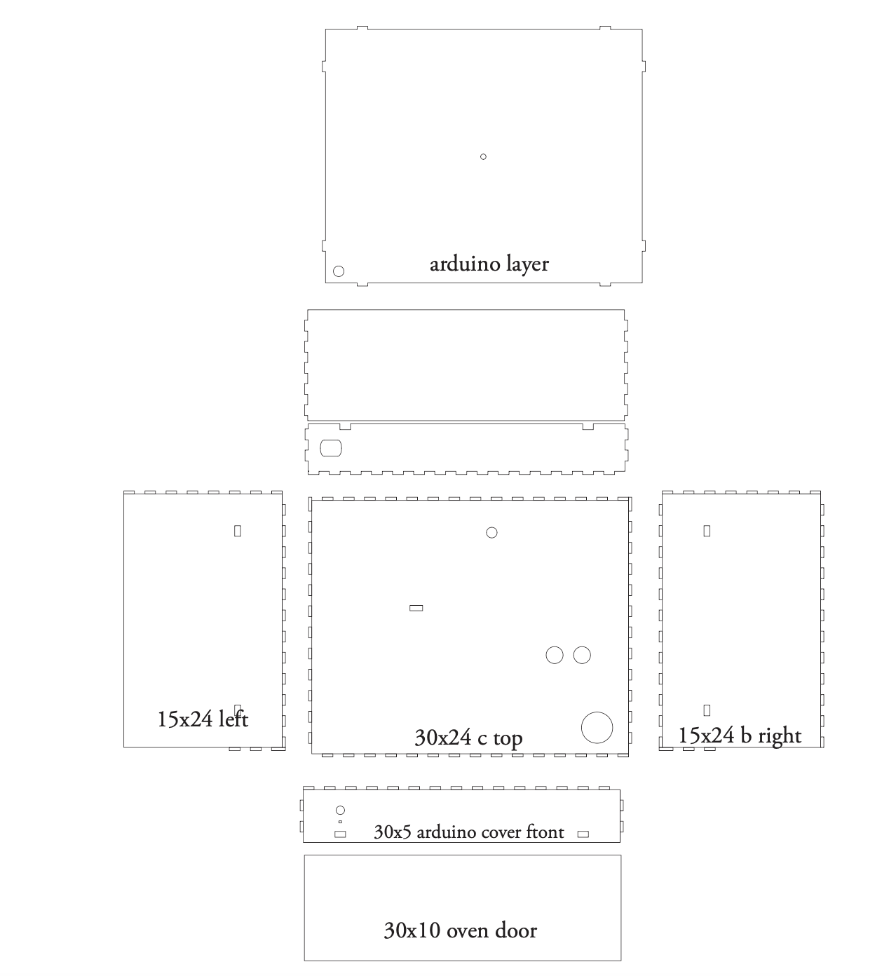
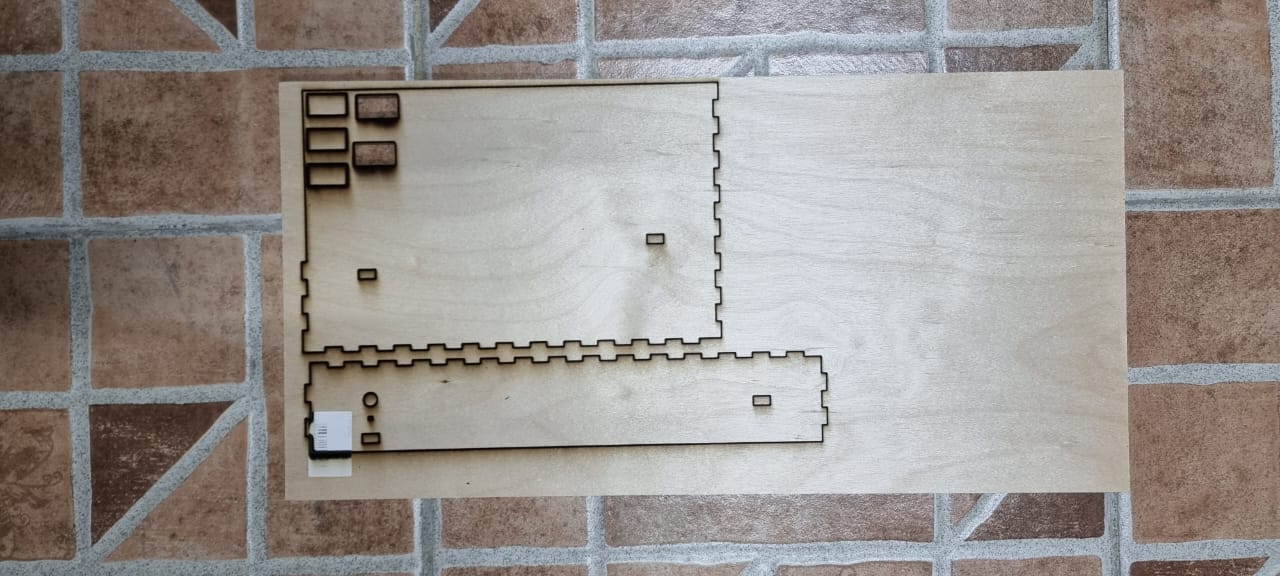
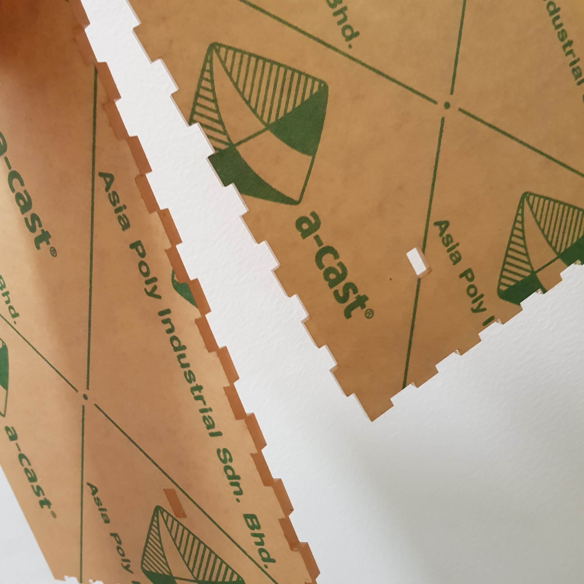
I wanted to use wood for the structure. I created the design to cut the wood in and used the “finger joint” method(I believe this is what it is called based on what I found online) to make sure that the structure is strong. (the letters on the align with a sketch I did of the structure on paper and labeling a, b, c… helped me keep track of the measurements)
testing
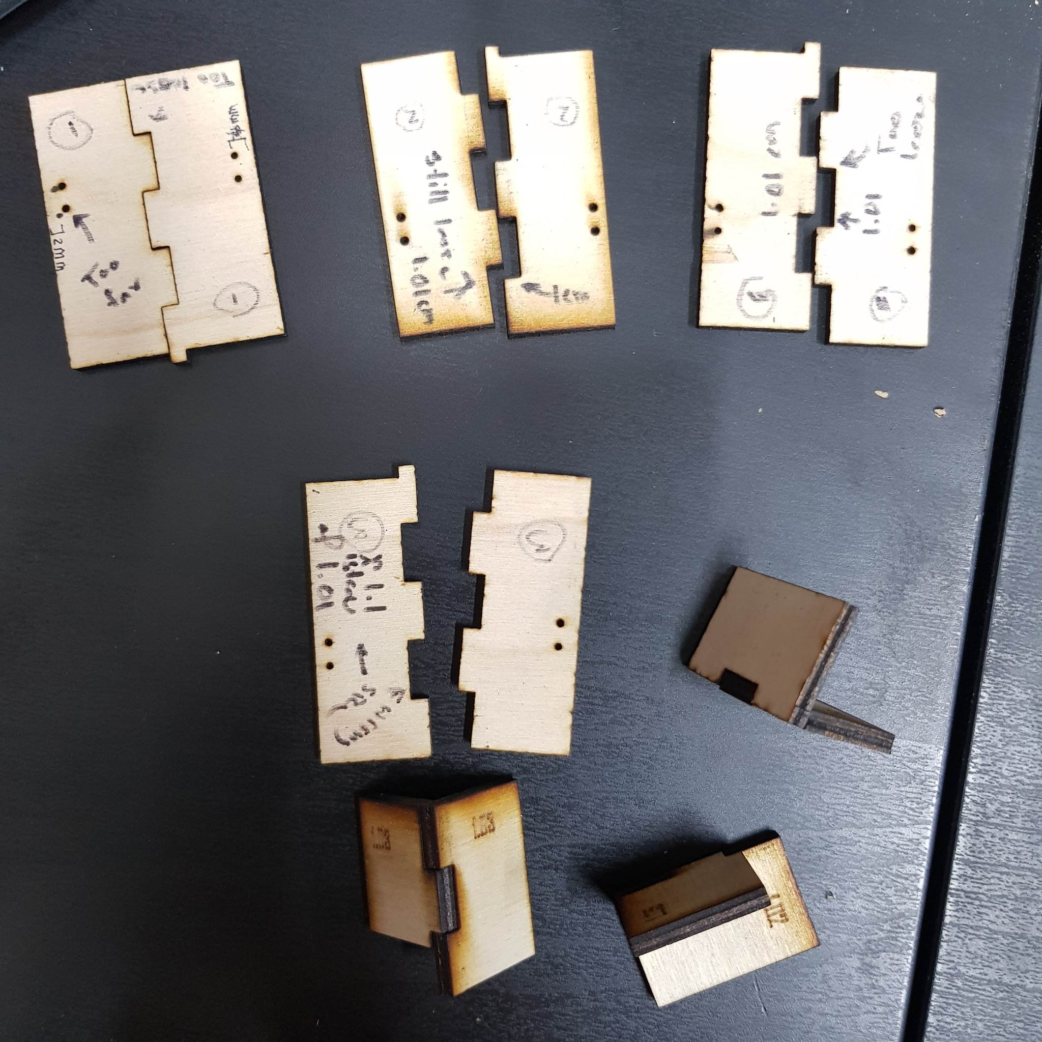
I started with 1 cm between each comb and a 1 cm comb with a height of 0.3(the width of the material)

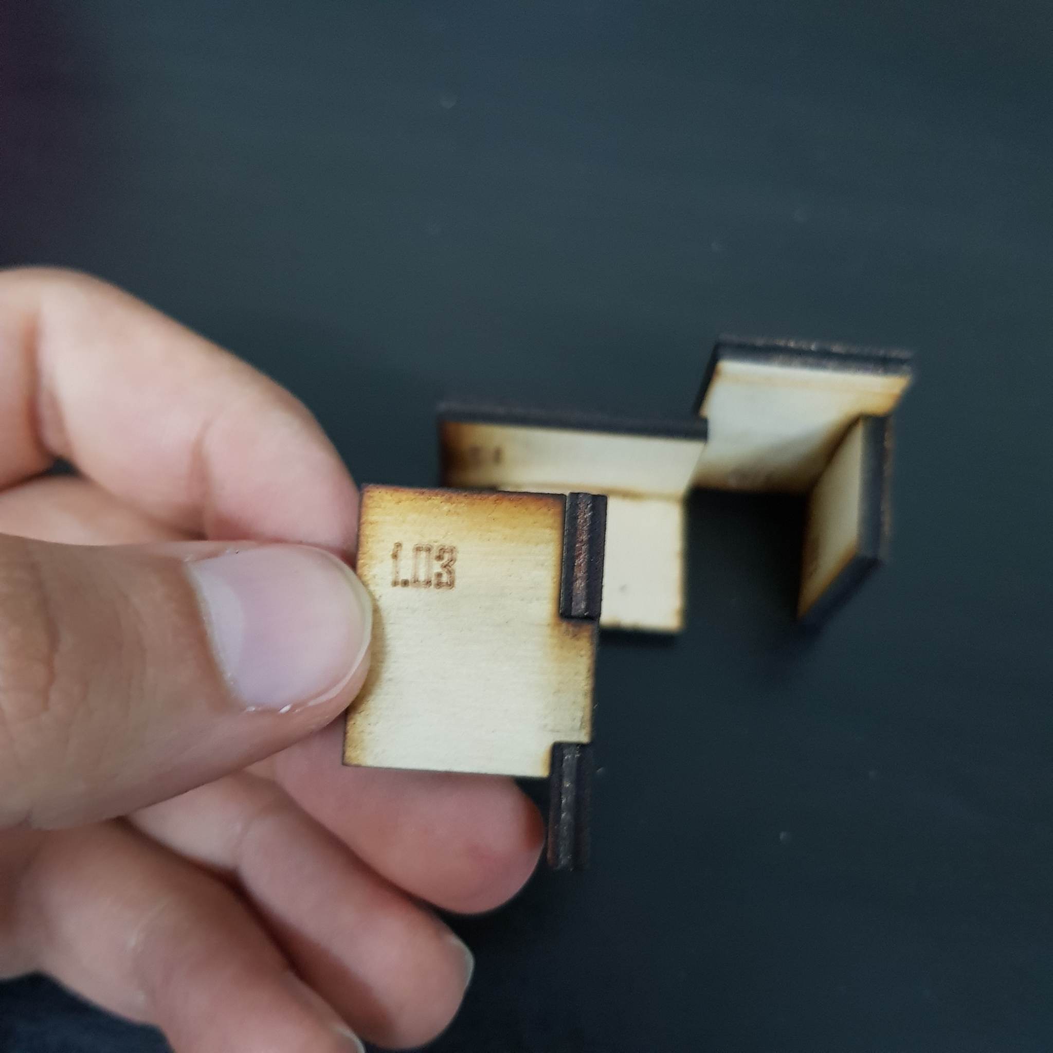
I tested that but it was a bit too loose(plot twist: it wasn’t, the little wiggle room is necessary). I settled for 1.03cm combs (with 1cm – 0.03/2 distance in between, not sure if this makes sense but this results in tighter fitting combs)

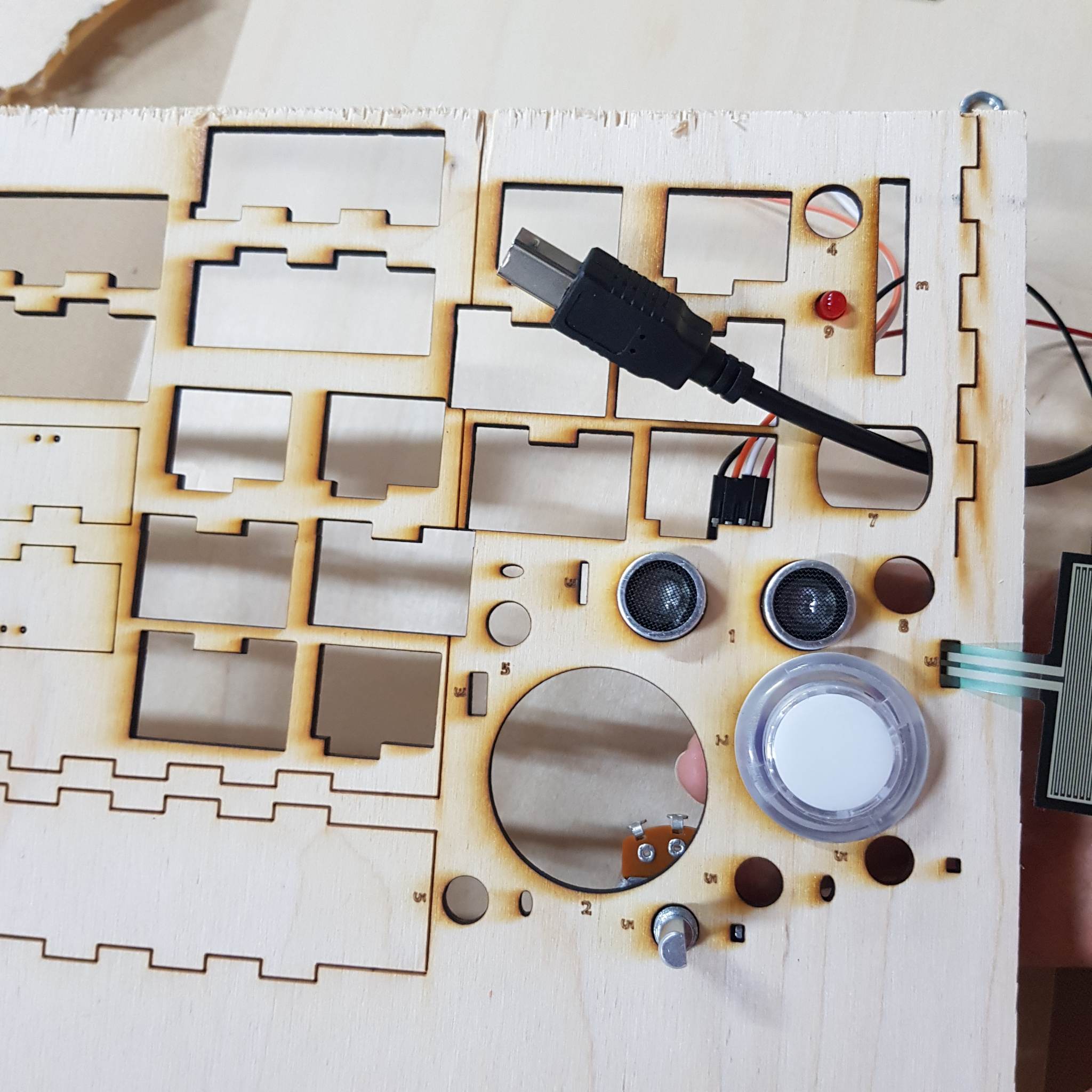
I also wanted to prepare the measurement for all the Arduino components that would be attached to the structure. I listed all the things that needed to be accounted for and measured all the components and their place on the structure.

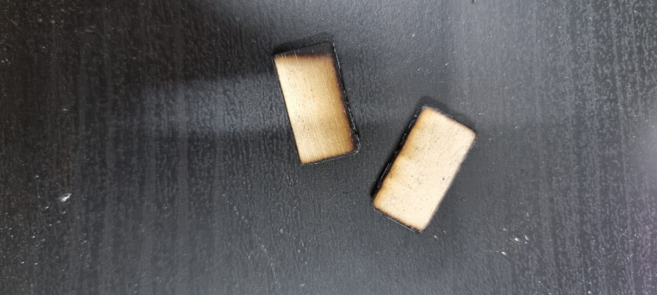
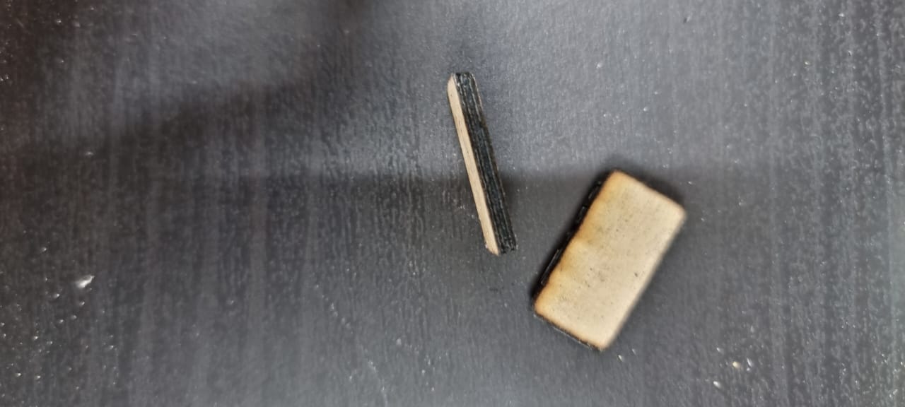
All the testing was done a scrap piece of wood that was the same thickness as the wood I intend to use for the project. After I was done with the design and testing I tried to laser cut the design the wood I plan to use for the project. However, the laser cutter wasn’t cutting the wood, I realized that the wood had a different (“structure?”) than the wood I used for testing. I assumed that changing the laser cutter settings could help, but it either didn’t cut the wood, or burnt the edges to ashes.
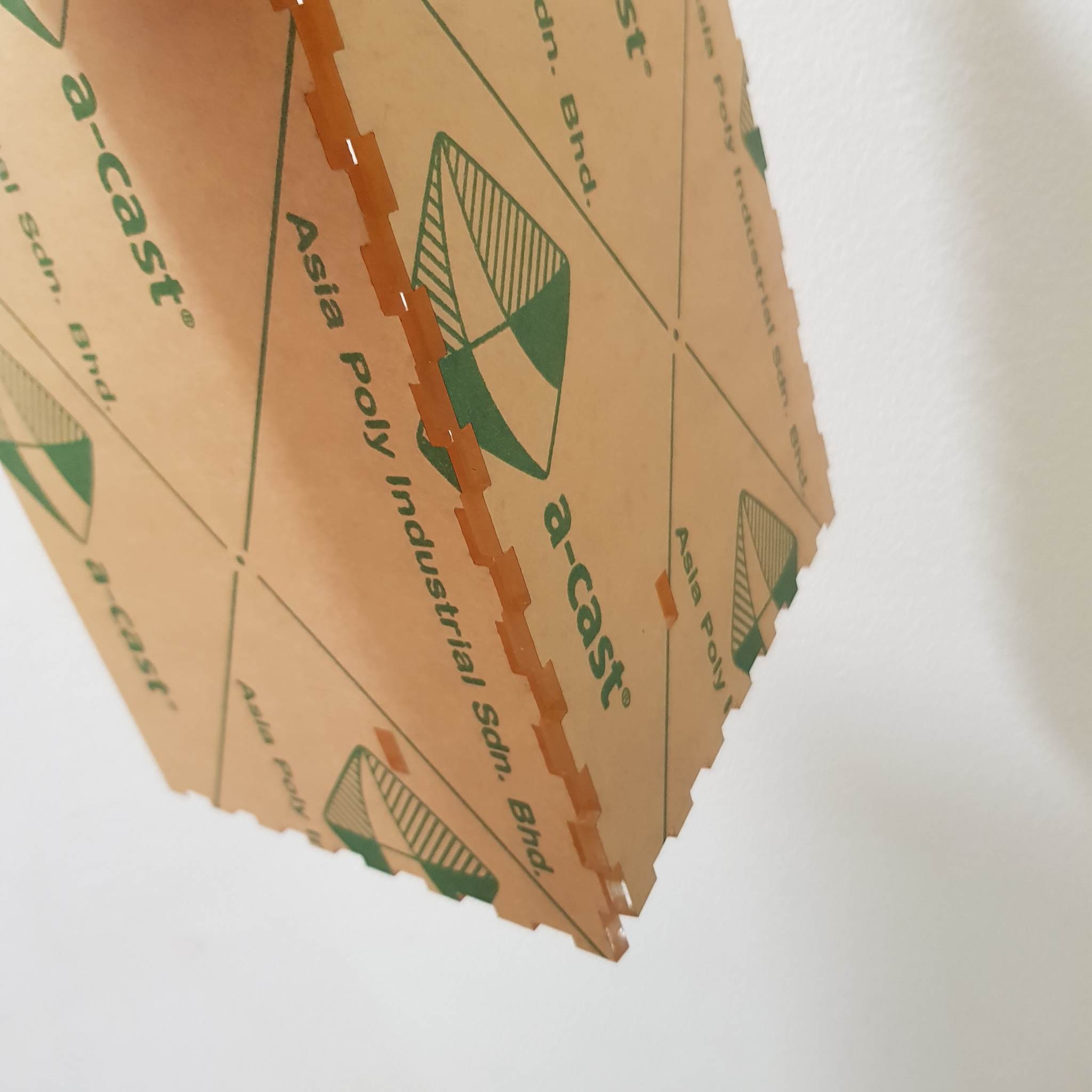
I didn’t have more of the wood I used for testing but I did have acrylic sheets. I switched the material I was going to use(even though I reallyy wanted to used wood).
I cut the design on the acrylic but had a problem(I also changed the height of the combs to the width of the new material). Then I faced another problem, the pieces didn’t fit together, I think there was an error when I changed the width of the combs, because the acrylic fit in certain angles.
cutting and painting
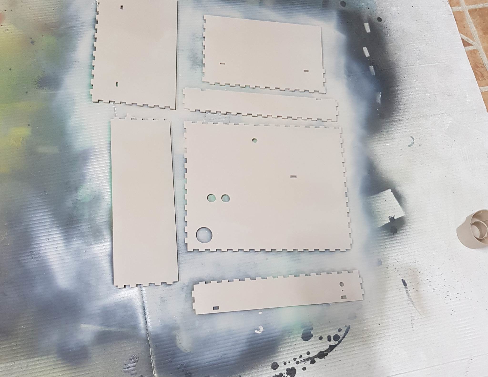
I decided to redo the combs with the original measurements (1 cm between each comb and a 1cm comb). This worked!
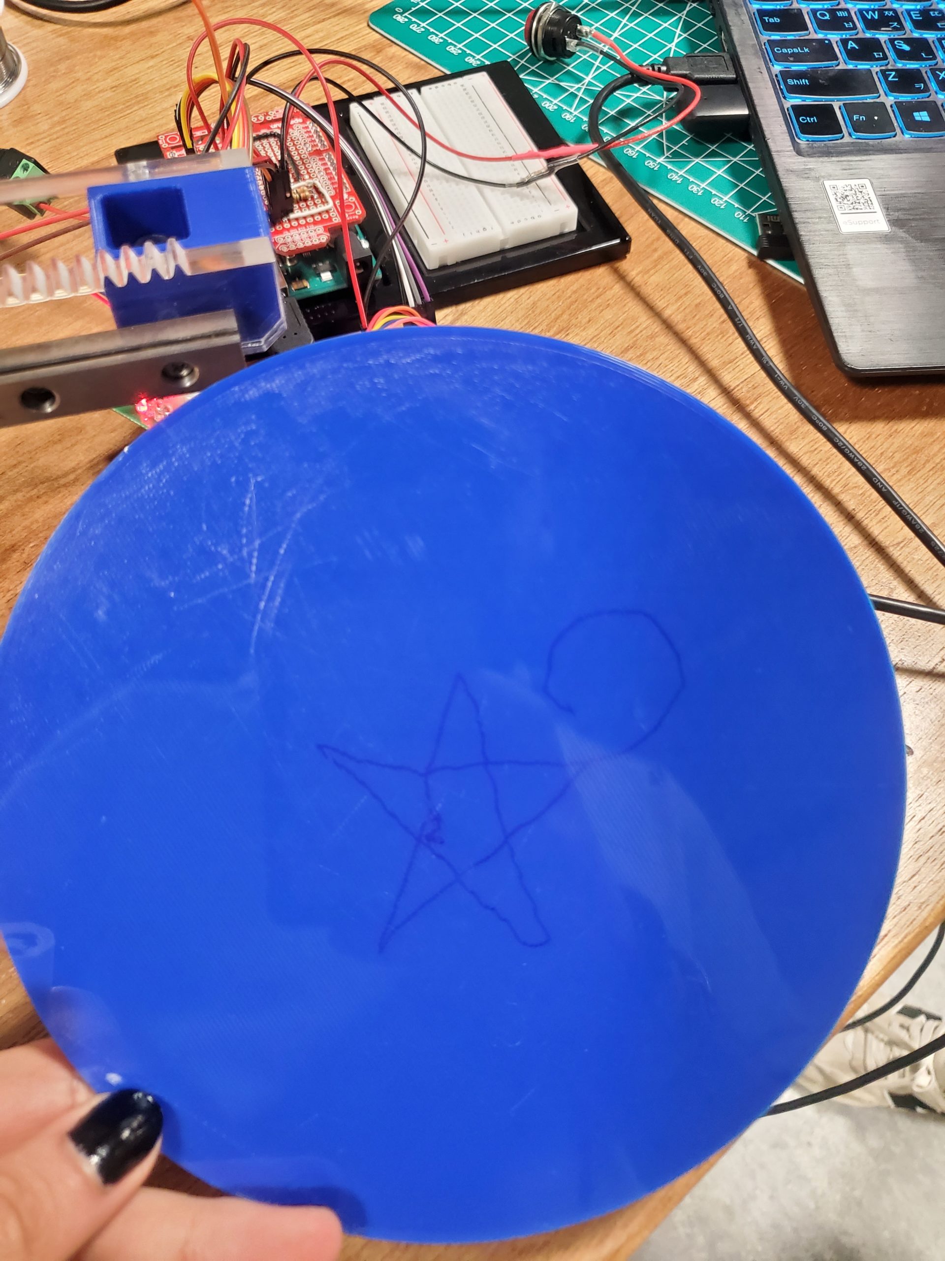
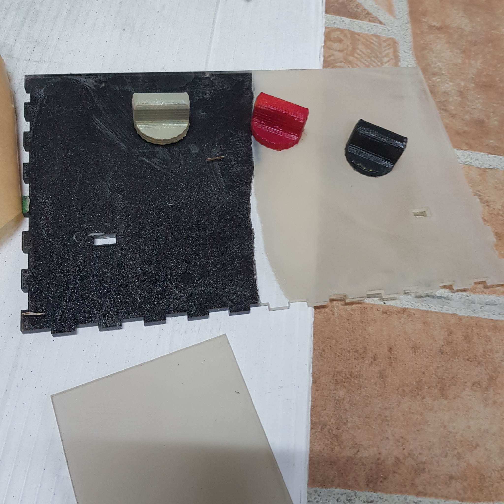
since I was using transparent acrylic I decided to paint it since having all the walls of the structure being transparent might be confusing or too distracting for the user.
I tested out a few colors then painted the structure(I also painted the oven knob so I tested some colors for that too).
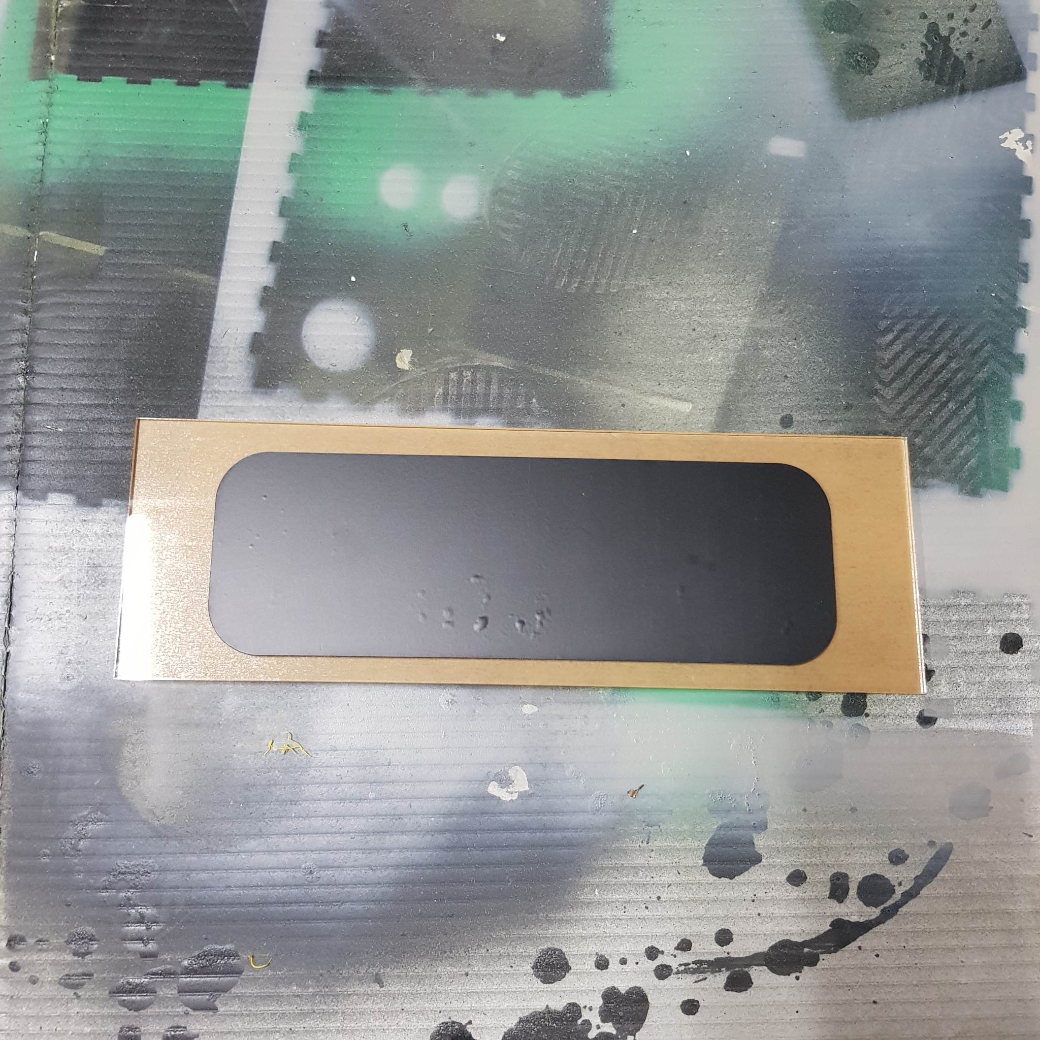
I also painted the oven door (the black part is a sticker to cover the parts I want to keep transparent.
assembly
I used super glue(and little white glue and glue gun in some parts) to stick all the parts together. There are a few structural things I would fix if I had time to make another prototype(for example I stuck the structure together in the “wrong” order, so it is slightly unaligned which affects the fit in some places.). I also used glue to add a hinge and stick some magnets to to the door. I also added magnets to the top back wall piece of the structure for easy access to the Arduino.
interface
I was not sure about how the interface would look like. I needed the task for each screen to be understandable with minimal text so that children who cannot yet read can still enjoy the game.
I decided to go with a front view, with a character that indicates what the current task is. I would also have the icons from the first instructions page to remind the child what to use for this task. Some of the pages also have bars that indicate how long a task should be done for. I also need to consider that I have limited drawing skills, I tried to find game assets online, but didn’t find ones that I really liked. I started sketching a very basic representation of how I want each screen to look:
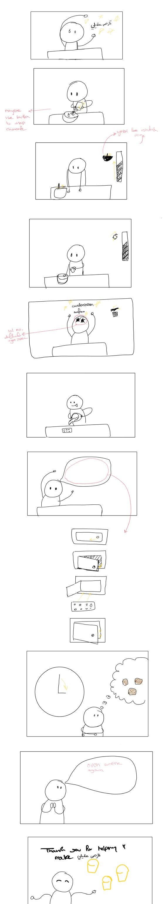
I tried this style but didn’t like it. I like the idea of the character wearing a Kandoora(Emirati traditional dress), but the eyes bordered on creepy and that was not the theme I was going for.

I asked my sister for input and she suggested a few things one of which is using colors without borders:

I liked this style more and I think I might stick with this style with a few adjustments.

Next steps
-
- I will need to connect the arduino into the structure
- I still need to finalize the p5js pages and find/make the graphics
- user testing!

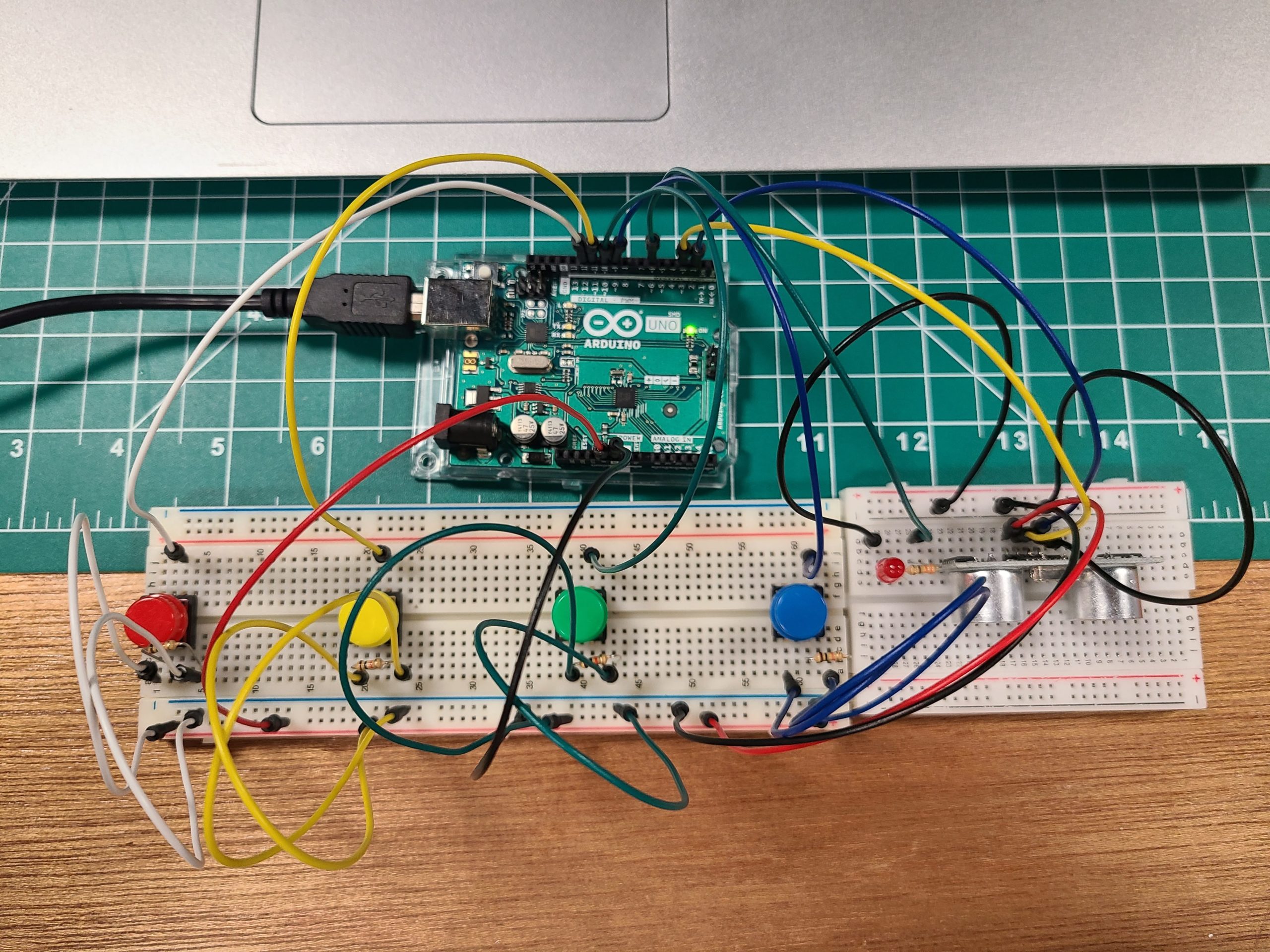
 The actual circuit: