
Concept/ Idea
For the project, we (Tim and Samyam) have decided to develop a system that lets the user sketch a diagram or shape on the p5.js canvas. This sketch then will be used to control the physical arm of our drawing platform. To accomplish this, we will send canvas data from p5.js to Arduino, controlling different parts of the drawing device.
The striking feature of the project is the interconnectivity of the drawing. The user can draw as many shapes or sketches as they desire, but everything will remain connected to each other. This idea is inspired by the Eulerian trail, where the floor is divided into multiple sections when multiple people step on it.
Hardware Design
Following the previous post, we have finalized our concept to be a polar coordinate pen plotter that plots a shape drawn on the computer screen. Unlike our previous design, we have decided to make a 2-DOF system (linear movement on one axis, and rotational motion around an orthogonal axis). Although the mechanical design of the machine became more complex, this will make the software much simpler. For the design, we used Autodesk Fusion 360 to create a 3d model, which was manufactured with a 3d printer and a laser cutter. For the precision of the plotter, we purchased a linear guide rail, commonly used in CNC machines and 3d printers; we used a stepper motor for controlled movement. Below is a 3 d model design for the project:
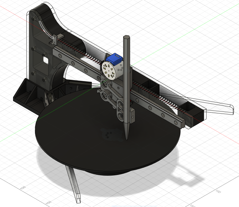
A rack and pinion system was used, so as a gear connected to a stepper motor rotates, it will move the whole pen carrier along a linear rail.
One distinctive feature of this plotter is that the position of the rotating (base) plate can be adjusted freely. This allows the user to produce different drawings every time he or she moves the base plate.
Because drawings on the screen use cartesian coordinates, we had to convert XY coordinates into polar coordinates. This was very simple because T:(X,Y) –> (r, θ), where r = sqrt(x^2+y^2) and θ = tan^-1(y/x). r will determine the movement of a linear DOF and θ will determine how much the base plate will rotate. Do you see how simple the calculation got compared to the previous design?
Making Parts
As mentioned above, a laser cutter and 3d printer was used to make parts.
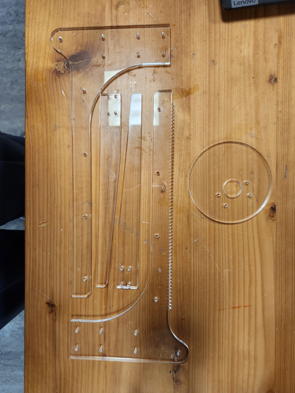
Laser Cutting
Due to the high rigidity of the acrylic plates, we decided to make the main body with acrylic parts. Based on our design, we were able to laser-cut the parts that we needed.
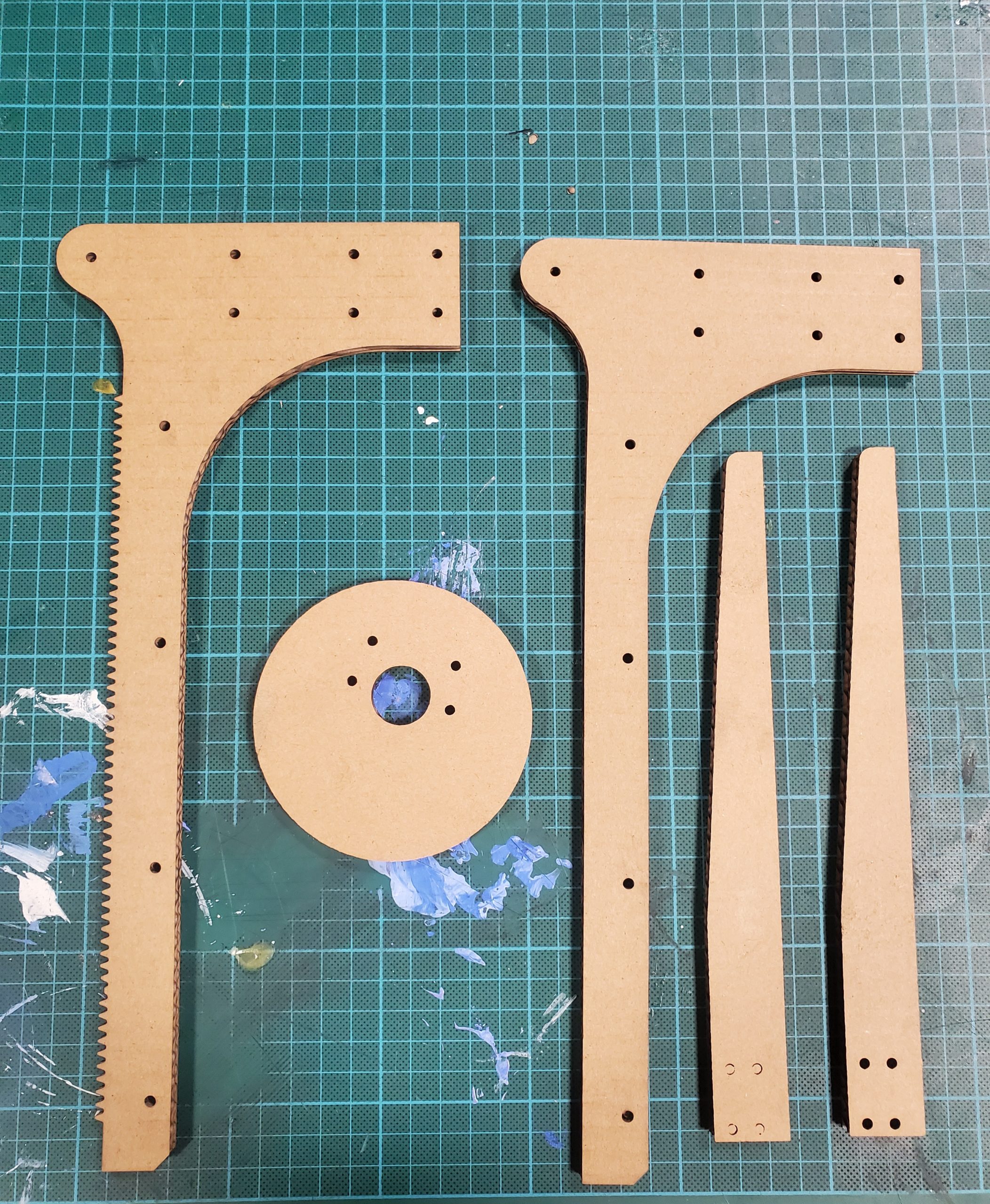
3D Printing
Parts that cannot be made with laser cutters were made using 3d printers. This included a base plate, a spacer between acrylic parts, and a pen moving mechanism.
P5.js Component
The preliminary phase of the project depends on the functionalities of the p5.js component. The user can use the mouse to draw shapes on the p5.js canvas; the shape will be replicated in the actual design using the Arduino component.
In order to sketch a shape on the canvas, the user can click the mouse and drag the cursor to draw the desired shape. This is regulated by two functions titled “mousePressed()” and “mouseReleased()” respectively. When the mouse is clicked, the global variable “isclicked” is set to True and when the mouse click is released, “isClicked” is set to False. This way, the global variable keeps track of the sketch being drawn.
Once the mouse is clicked, the program checks the position of the cursor – if it is static while being tracked, the position is ignored, i.e., the user must move the cursor, while the mouse is being clicked, so that a sketch can be drawn on the screen. It is facilitated by the following code:
// Make sure the mouse is clicked and cursor position is different
if (isClicked && mouseX !== pmouseX && mouseX !== pmouseY)
{
  // Create a vector and add it to the list
  // let pt = createVector(mouseX, mouseY);          // When origin is at the top-left corner
  let pt = createVector(mouseX - width/2, mouseY - height/2);
  positions.push(pt);
  // console.log(pt.x, pt.y);


  // Mapping Cartesian to Polar and appending it in mappedPositions array
  let temp_list = [];
  temp_list = cartToPolar(pt.x, pt.y)
  let pt_mapped = createVector((temp_list[0] * one_px_mm), temp_list[1]);
  mappedPositions.push(pt_mapped);

}
Here, we can see, if the aforementioned conditions are met, a new vector based on the cartesian location of the cursor is created and appended to the (global variable) list “positions”. The entire canvas is translated to the middle of the canvas, that’s why a certain amount is subtracted to the x and y coordinates before appending to the list. Similarly, with the help of a function titled “cartToPolar()”, each vector in the cartesian coordinates is converted to polar coordinates equivalent and appended to a list titled “mappedPositions[]”.
function cartToPolar(x, y)
{
  let radius, angle;

  radius = sqrt(sq(x) + sq(y));
  // console.log(radius);

  angle = atan(y/x);
  // console.log(angle);

  let temp_list = [];
  temp_list[0] = map(radius, 0, sqrt(2 * sq(width/2)), 0, disc_radius);         // Mapped radius
  temp_list[1] = angle;

  return temp_list;

}
The program also consists of two manually coded buttons — RESET and SEND DATA. The former reset the canvas and resets the required variables so that the sketch can be redrawn from the beginning. While the latter is used to send data to the Arduino connected to the system. Both these functions derive from a template function titled “button()” that takes text, x, y coordinates, height and width of the button as arguments. To develop the SEND DATA functionality, a function named “send_data_button()” calls the main button function with the required parameters. The main function returns a boolean value [1 if the cursor is within the button and 0 otherwise]. If the boolean value is 1 and the button is pressed, the values in the “mappedPositions[]” list are forwarded to the Arduino using an inbuilt serial.write() function. In each iteration, the angle of the coordinate is transmitted following its radius.
function reset_button()
{
  let x = 26;
  let y = canvas_h - 70;
  let w = 125;
  let h = 50;

  // If the cursor is within the button button() function returns 1, else 0;
  let resetBool = button("RESET", x, y, w, h);

  // Resetting sketch if the cursor iswithin the button and mouse is clicked
  if (resetBool && mouseIsPressed)
  {
    positions = [];
    mappedPositions = [];
    isClicked = false;
  }

}
The p5.js component also comprises different functions like choosePort(), openPort(), serialEvent() and so forth to keep track of the port selection, data transmission as well as error handling.
Arduino Component
Arduino is connected to 2 stepper motors, each controlled by different stepper drivers. The Arduino will read data sent from p5js and move the pen and plate accordingly. Total of 2 switches will be connected to the board, both for homing the pen carrier (one push button and one limit switch).
When the button is pressed, the Arduino will begin to move the pen carrier back until the carrier hits the limit switch. Once the limit switch is closed, the Arduino will move the pen carrier slightly front and move the carrier back until it hits the switch again. The second part will be done at a much slower speed for accuracy. Homing a pen carrier is significant because the machine must always be aware of the pen’s current position. Homing allows the machine to always start from the same initial position.
This is the sample code showing how the code will work (no motors added yet):
const int limitSw = 7;

const int homeButt = 8;

long long currentTime = 0;

bool homing = false;

bool reachEnd = false;

void setup() {

  // put your setup code here, to run once:

  pinMode(limitSw, INPUT);

  pinMode(homeButt, INPUT);

  Serial.begin(9600);

}


void loop() {

  // put your main code here, to run repeatedly:

  if(!homing && digitalRead(homeButt) == 1){

    homing = true;

  }


  if(homing){

    if(!reachEnd){

      Serial.println("homing fast");

      if(digitalRead(limitSw) == 1){

        Serial.println("SW pressed");

        reachEnd = true;

        currentTime = millis();

      }

    }

    else{

      Serial.println("homing slow");

      if(digitalRead(limitSw) == 1 && millis() - currentTime > 500){

        Serial.println("SW slow pressed. homing complete");

        homing = false;

        reachEnd = false;

      }

    }

  }

}
The other part of the code will include moving each part accordingly to the coordinate values from p5js. This would be relatively easy to achieve because we can calculate how much each part will move in mm when the motor turns by half or a single step.
Further coding can be done once we are ready with fully assembled hardware.
Future Plan
The time it takes to 3D print parts is the only problem we are facing until now. Once we are done printing our parts, we will be able to assemble the parts together soon.
For now, the future plan includes the functionality to successfully coordinate the Arduino component with the data sent from the p5.js component. Since the canvas sketch is drawn based on cartesian coordinates, while the physical drawing is based on polar coordinates, we are planning to program the project so that artistic output is achieved.
Demo
The software phase of the project can be tested here using this link. The project will be completed once the printing phase is completed.