
DESIGN
Because I am still unfamiliar with circuit building, what I created for this project is rather simple. Two elements on the board, a digital switch and a light sensor control two LED’s. When the program starts, the lights flicker in an alternating pattern with a starting interval of 500 milliseconds. However, the frequency at which the LED’s flicker is dependent on the light sensor: low levels of light cause the lights to flicker on a larger interval, and high levels of light cause the lights to flicker on a shorter interval. Finally, the switch changes the LED’s from flickering in an alternating pattern to a simultaneous pattern.
MATERIALS
The materials I used for this project are listed below:
- 2 LED’s
- 3 10k Ohm resistors
- wires
- switch
- light sensor
BUILDING THE CIRCUIT
I began by building a simple 2 LED circuit like we had practiced in class. I then incorporated the switch, and finally I extended it to include the light sensor. A photo of the board is shown below: 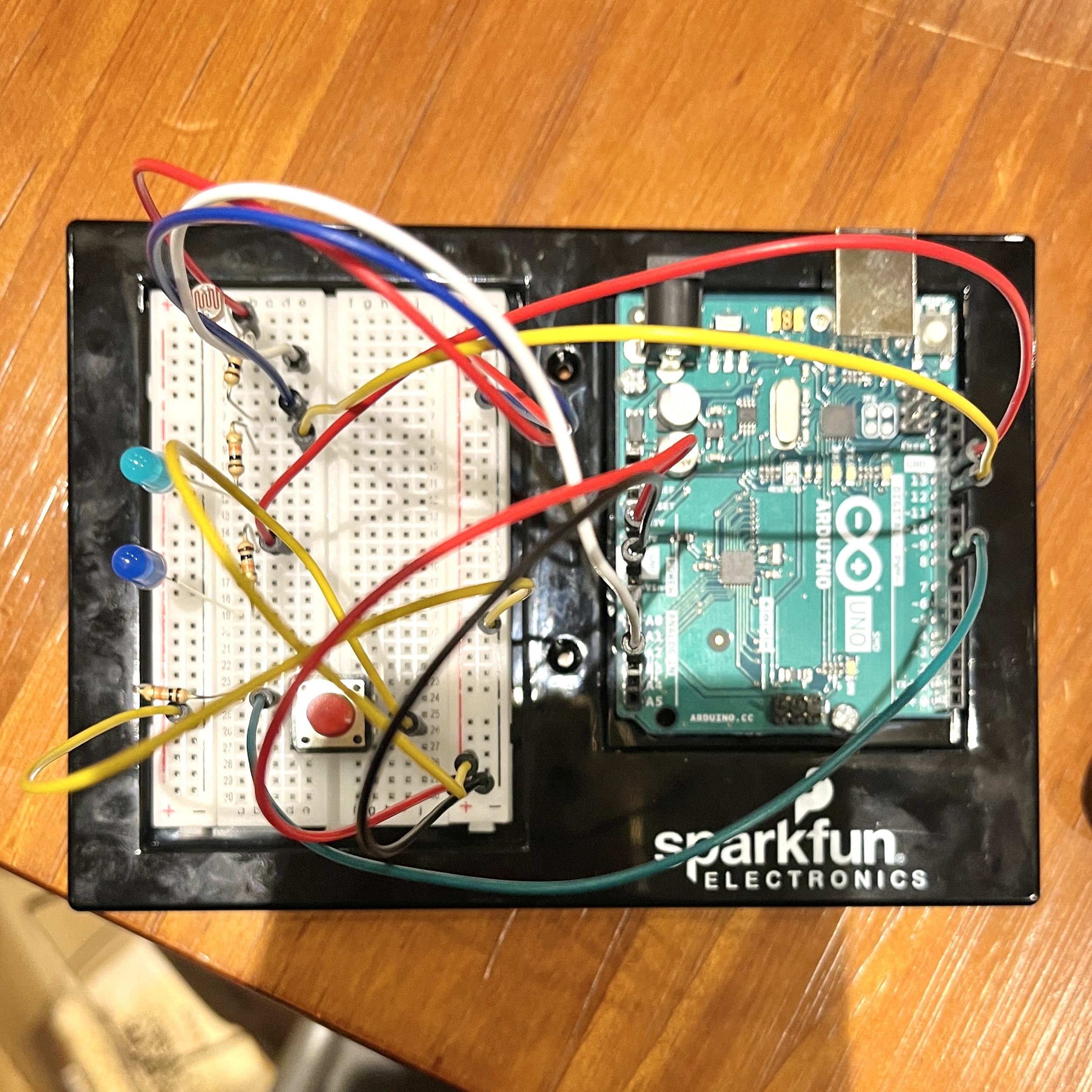
CODE
The most challenging part of this project was getting the button to toggle. In class, we had only worked with buttons that do something once when clicked; however, what I wanted was for the LED’s to maintain a certain pattern from the time the button was pressed to the time it was pressed again. To achieve this, I referenced the Arduino website. Ooutside of the setup() and loop() function, I define variables currentButtonState, previousButtonState, and ledState. The currentButtonState is obtained by reading the input at pin 8, which is where the switch on the board is connected. The ledState is initially set to LOW and is the variable that defines what the LED’s do. In the loop() function, the state of the button is defined by the following if statement:
if (previousButtonState == HIGH && currentButtonState == LOW) {
  ledState = !ledState;
  digitalRead(ledState);
}
This statement essentially says that when the button is pressed, flip the ledState from HIGH to LOW and vice versa. In separate if statements, I define the behavior of the LED’s, which has to options: flash simultaneously when the ledState is HIGH or flash alternating when the ledState is LOW. The code is shown below:
if (ledState) {
  digitalWrite(LED1, LOW);
  delay(interval);
  digitalWrite(LED1, HIGH);
  digitalWrite(LED2, HIGH);
  delay(interval);
  digitalWrite(LED2, LOW);
}

if (!ledState) {
  digitalWrite(LED1, HIGH);
  delay(interval);
  digitalWrite(LED1, LOW);
  digitalWrite(LED2, HIGH);
  delay(interval);
  digitalWrite(LED2, LOW);
}
FINAL PRODUCT
REFLECTIONS
As mentioned above, I find building circuits very challenging, while the coding portion comes more naturally to me. I am relatively comfortable coding in C, so making the transition to using C++ was not too difficult, and I actually had a lot of fun experimenting with the code. I do wish that this project could have been more creative and visually appealing, but I don’t think time allowed. I spent a lot of time taking apart the board and rebuilding the board several times so that I could better understand how the circuit was working.