
SAGA-GT Car Game
We are building a remotely controlled car that will feature both autopilot mode and manual driving mode. The user will have the choice to decide which mode they want to choose to drive the car.
User-controlled: using arrows keys through p5js, we will make a mini-game in p5js or a real obstacle course if we have time after completion of this mode.
Follow a track or the user: using infrared sensors, we want to make the car move independent of input from the user by following a line on the track.
Arduino Components
- Arduino Uno (we are going to move it to the MEGA board)
- 2 IR Range Sensor
- 4 Wheels
- 4 Motors
- 1 ultrasonic sensor
- 1 LDR
- 2 Motor drivers
- Battery DC
- Acrylic Sheet
- Battery Holder
Implementation
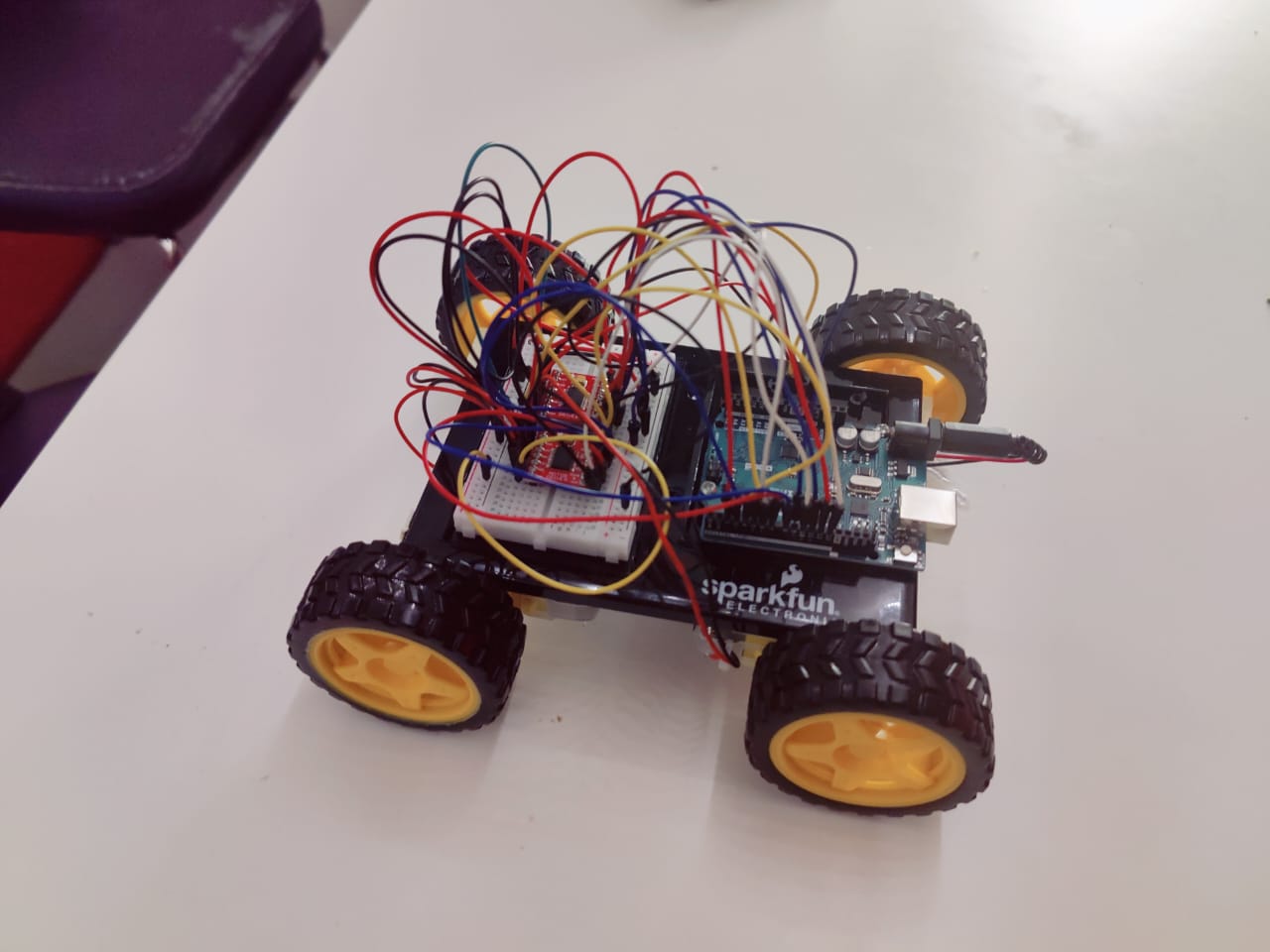
We started by taping the motors using double sided tape and sticking it to the acrylic sheet. Then we connected the wheels to the motor and wired it to the motor driver. We manage to fit all the pins on the Arduino Uno and after couple hours of figuring out the wiring we got both the motor driver on the breadboard. Then came the challenging part of getting the pins defined correctly in the code and using the example code to build up on our car driving code.
We made the car so that it can move in all directions, using two motor drivers and four motors (4 Wheel Drive). This allows the user to control the car’s movement direction using arrow keys on P5.js through Serial Communication with the Arduino connected to the car. We have the manual driving mode working now and the car can be controlled manually from the p5.js interface with the arrow keys.
The p5.js is serially transmitting a direction flag (integer) that is indicating the driving direction and the Arduino is reading this flag and using switch statements to make the car move. These switch statements control the motors’ speeds and rotation directions.
We decided to manually control the movement of the car – without the IR controller – because this is the most functionally important part of this project. We spent the weekend understanding how the motors work and what possibilities there are coding features for motors in Arduino. We are now confident enough in our basic understanding of motors to start finalizing the project.
Here is a video of the car driving:
Here is the p5js sketch we made:
let dir = 0;
let direction = 0;

function setup() {
  createCanvas(640, 480);

  textSize(18);
}

function draw() {

  if (!serialActive) {
    text("Press Space Bar to select Serial Port", 20, 30);
  } else {
    text("Connected", 20, 70);
  }
  switch(direction) {
  case 0:
    dir = 0;
    break;
  case 1:
    dir = 1;
    break;
  case 2:
    dir = 2;
    break;
  case 3:
    dir = 3;
    break;
  default:
    // code block
  }

  print(dir);
}

function keyPressed() {
  if (key == " ") {
    // important to have in order to start the serial connection!!
    setUpSerial();
  }
  else if (keyCode == UP_ARROW) {
    direction = 0;
  }
  else if (keyCode == LEFT_ARROW) {
    direction = 1;
  }
  else if (keyCode == RIGHT_ARROW) {
    direction = 2;
  }
  else if (keyCode == DOWN_ARROW) {
    direction = 3;
  }
}

function readSerial(data) {
  ////////////////////////////////////
  //READ FROM ARDUINO HERE
  ////////////////////////////////////

  if (data != null) {
    //////////////////////////////////
    //SEND TO ARDUINO HERE (handshake)
    //////////////////////////////////
    let sendToArduino = dir + "\n";
    console.log(sendToArduino)
    writeSerial(sendToArduino);
  }
}
Here is the Arduino code:
//Motor controls
const int ain1Pin = 3;
const int ain2Pin = 4;
const int pwmAPin = 5;

const int ain1Pin_2 = 13;
const int ain2Pin_2 = 12;
const int pwmAPin_2 = 11;

const int bin1Pin = 8;
const int bin2Pin = 7;
const int pwmBPin = 6;

const int bin1Pin_2 = 9;
const int bin2Pin_2 = 2;
const int pwmBPin_2 = 10;

int dir = 0; //0 - forward, 1 - right, 2 - left, 3 - reverse
bool reverse = false;

void setup() {

  //setting all motor controls to output
  pinMode(ain1Pin, OUTPUT);
  pinMode(ain2Pin, OUTPUT);
  pinMode(pwmAPin, OUTPUT);

  pinMode(ain1Pin_2, OUTPUT);
  pinMode(ain2Pin_2, OUTPUT);
  pinMode(pwmAPin_2, OUTPUT);

  pinMode(bin1Pin, OUTPUT);
  pinMode(bin2Pin, OUTPUT);
  pinMode(pwmBPin, OUTPUT);

  pinMode(bin1Pin_2, OUTPUT);
  pinMode(bin2Pin_2, OUTPUT);
  pinMode(pwmBPin_2, OUTPUT);

  Serial.begin(9600);

  // start the handshake
  while (Serial.available() <= 0) {
    Serial.println("0,0"); // send a starting message
    delay(300);            // wait 1/3 second
  }
}

void loop() {

  while (Serial.available()) {

      if (!reverse){
          digitalWrite(ain1Pin, LOW);
          digitalWrite(ain1Pin_2,HIGH);

          digitalWrite(ain2Pin, HIGH);
          digitalWrite(ain2Pin_2,LOW);

          digitalWrite(bin1Pin, HIGH);
          digitalWrite(bin1Pin_2,LOW);

          digitalWrite(bin2Pin,LOW);
          digitalWrite(bin2Pin_2,HIGH);
      }

      else {
          digitalWrite(ain1Pin, HIGH);
          digitalWrite(ain1Pin_2,LOW);

          digitalWrite(ain2Pin, LOW);
          digitalWrite(ain2Pin_2,HIGH);

          digitalWrite(bin1Pin, LOW);
          digitalWrite(bin1Pin_2,HIGH);

          digitalWrite(bin2Pin,HIGH);
          digitalWrite(bin2Pin_2,LOW);
      }


      dir = Serial.parseInt();

      //completing the "handshake"!!!!!!!!!!!!!!!!!!!!!
      Serial.println(dir);

      if (Serial.read() == '\n') {
          switch(dir) {
          case 0:
            reverse = false;
            analogWrite(pwmAPin, 255);
            analogWrite(pwmAPin_2, 255);

            analogWrite(pwmBPin, 255);
            analogWrite(pwmBPin_2,255);
            break;
          case 1:
            analogWrite(pwmAPin, 255);
            analogWrite(pwmAPin_2, 0);

            analogWrite(pwmBPin, 255);
            analogWrite(pwmBPin_2,255);
            break;
          case 2:
            analogWrite(pwmAPin, 255);
            analogWrite(pwmAPin_2, 255);

            analogWrite(pwmBPin, 255);
            analogWrite(pwmBPin_2, 0);
            break;
          case 3:
            reverse = true;
            analogWrite(pwmAPin, 255);
            analogWrite(pwmAPin_2, 255);

            analogWrite(pwmBPin, 255);
            analogWrite(pwmBPin_2,255);
            break;
          }
      }
  }

  //GO THROUGH THE KEYPRESSED IN DRAW LOOP OF P5JS

}
Plans
At first, the P5js sketch will have an initial menu screen with the two modes for the user to choose from. If the user chooses the autopilot mode, the car will be able to move around and avoid obstacles (obstacle detections) and also be able to drive automatically on a predefined course/ path (by following a black tape on the course using IR sensors). We plan to build a driving course to accompany our car for this project. The user use this course for “test-drives”.
We plan to add wireless transmission using the XBEE shield and chip we checked out as per the Professor’s suggestion. The Arduino connected with the computer will be in Serial Communication with p5js and will send out signals to the Arduino connected with the car to maintain the p5js to car communication. We also plan on adding motion sensors to the car to gauge braking distance – we will add a simply braking functionality too.
In summary:
- Add wireless Transmission feature
- Line follower (Auto driving feature): Add 2 infrared sensors
- Glue the motors to the board and and align the wheels properly
- Screw the Arduino firmly to the board
- Create the driving course
- Work on the P5.js interface