
Goal and Implementation
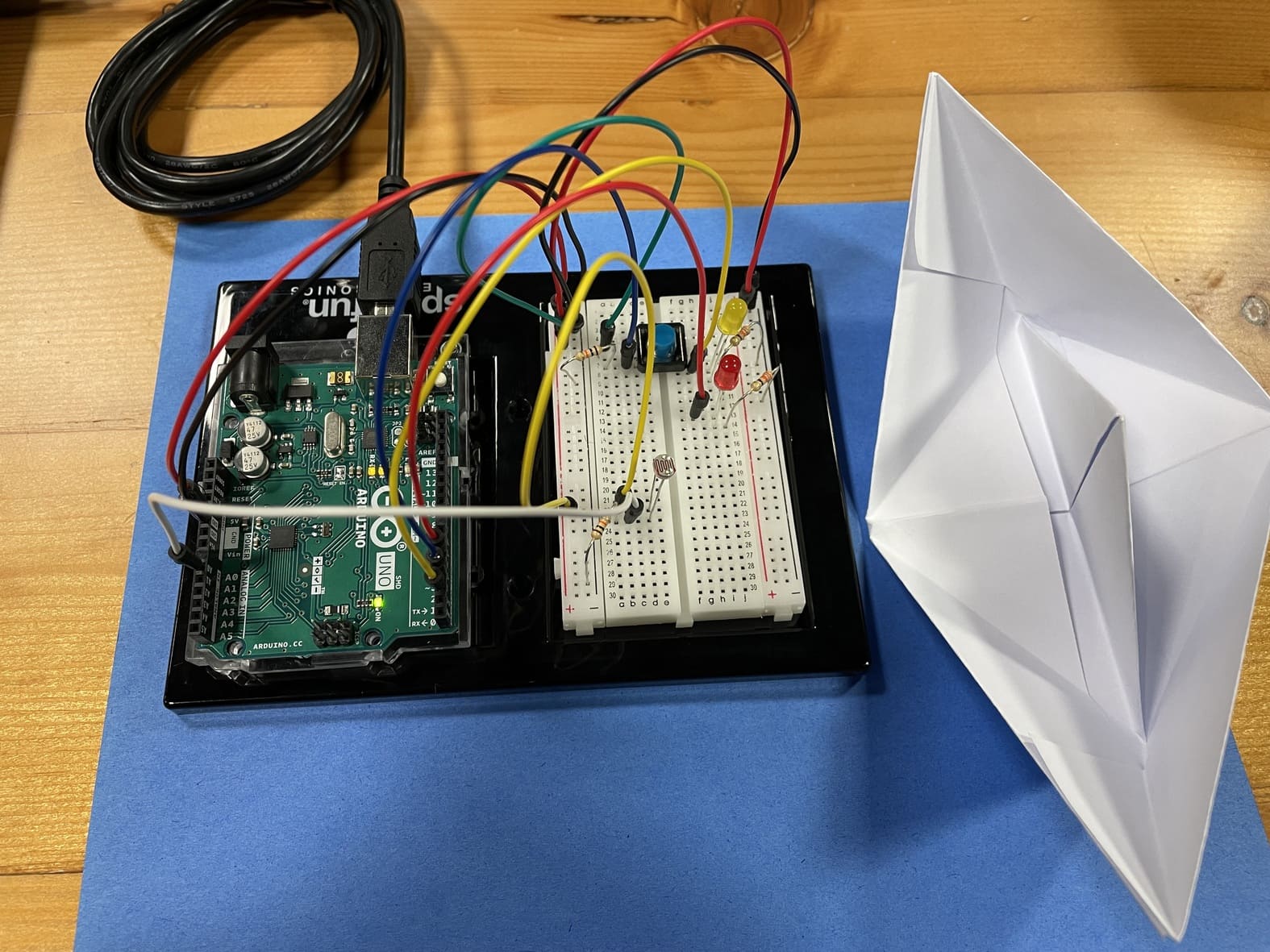
With this assignment I set out to buid a simplified lighthouse using two seperate LEDs.
The yellow LED is controlled by a switch (digital input). So this LED is either turned on or off, similar to how a lighthouse works at set times during the night.
The red LED is dependant on the intensity of light in the environment. It’s brightness is mapped to the resistance of the LDR that varies with light. Therefore, in absence of light, the LDR’s resistance increases, and the LED glows brighter. In real life, this would mean as the sun sets, the lighthouse would emit more light, hence being more visible to far off ships.
These two LED’s represent two plausable ways lighthouses function. The LDR value is read by the analogue input and the switch value is read by the digital inputs.
const int yLedPin = 2;
const int rLedPin = 7;
const int buttonPin = 3;
bool onOff = LOW;
byte prevButtonState = LOW;

void setup() {
  // put your setup code here, to run once:
  pinMode(yLedPin, OUTPUT);
  pinMode(rLedPin, OUTPUT);
  pinMode(buttonPin, INPUT);
  Serial.begin(9600);

}

void loop() {
  // put your main code here, to run repeatedly:
  byte buttonState  = digitalRead(buttonPin);
  int lightValue = analogRead(A0);
//  Serial.println(lightValue);
  int mappedLightValue = map(lightValue, 500, 900, 255, 0);

  int constrainedLightValue = constrain(mappedLightValue, 0, 255);
  analogWrite(5, constrainedLightValue);

  if (buttonState == HIGH && prevButtonState == LOW) {
    // change blinking to not blinking
    onOff = !onOff;
    digitalWrite(yLedPin, onOff);
  }
  prevButtonState = buttonState;

}