Week 8: Hands-free switch

Inspiration:

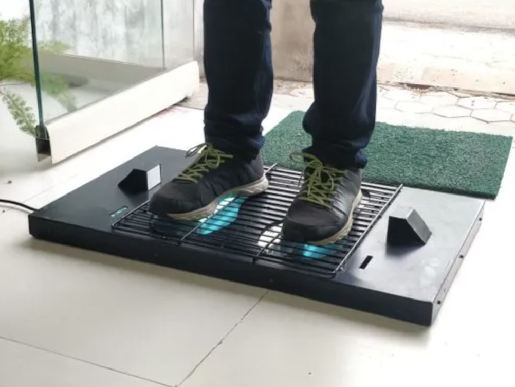
For this assignment, I was mainly inspired by the UV shoe sanitizer that is used to help fight bacteria in hospitals.

Process:

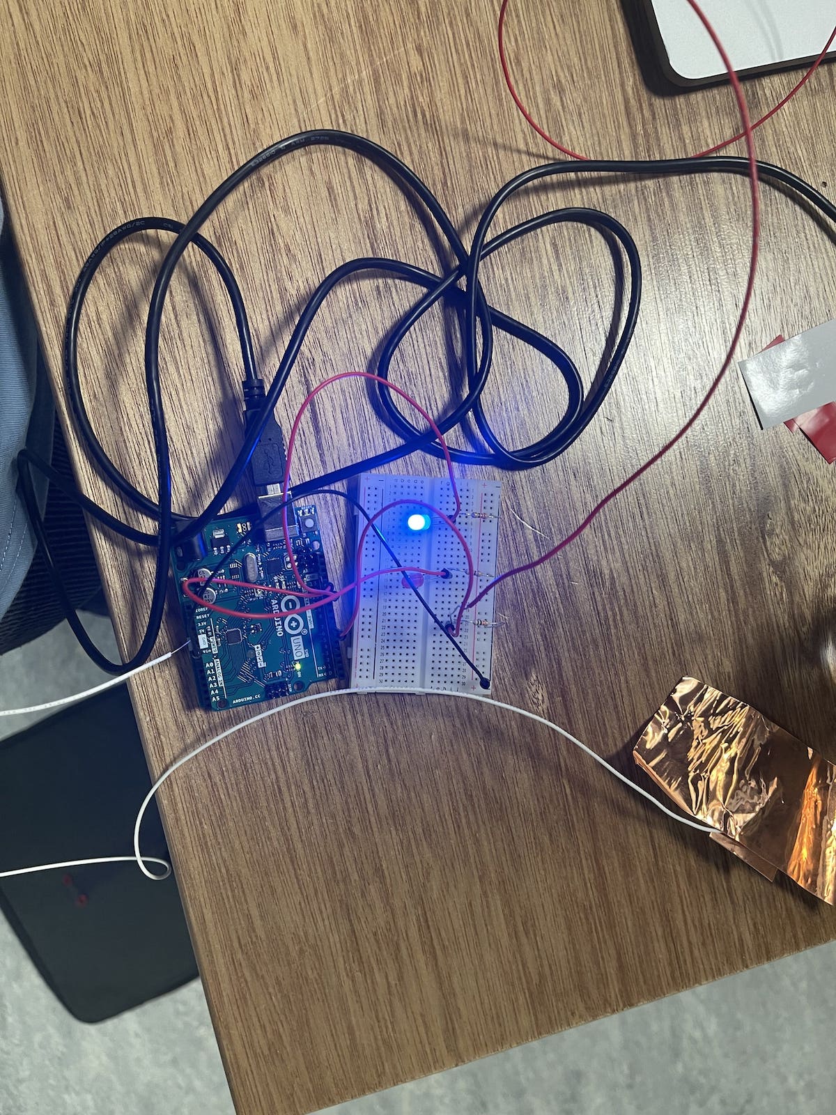
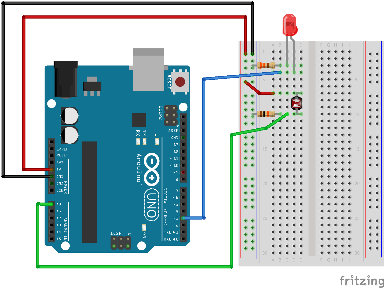
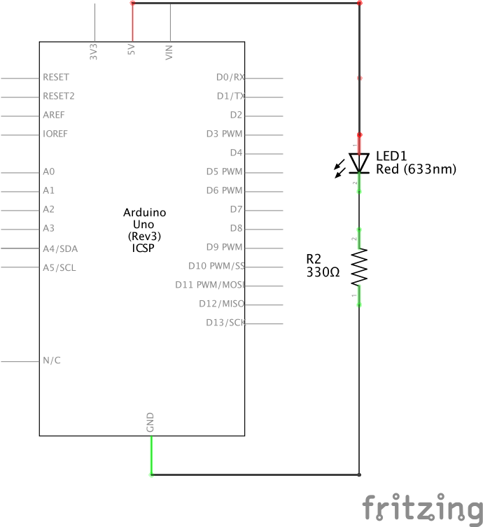
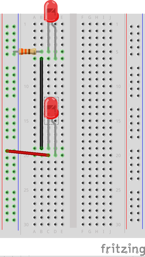
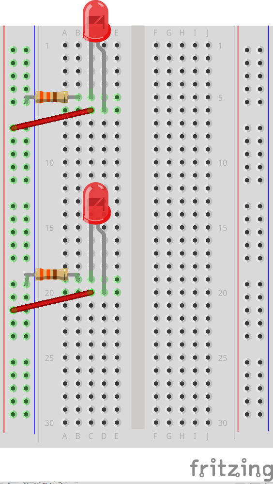
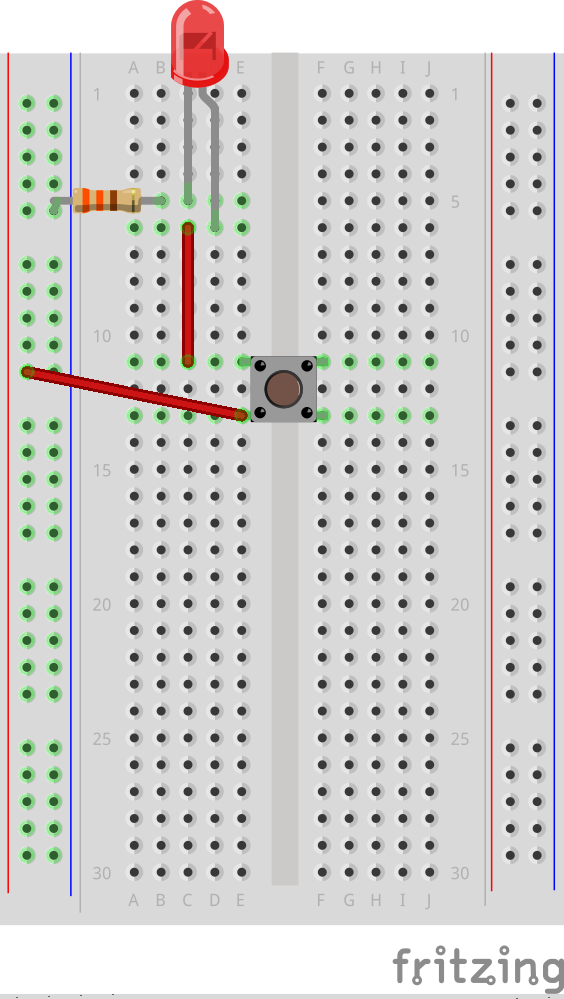
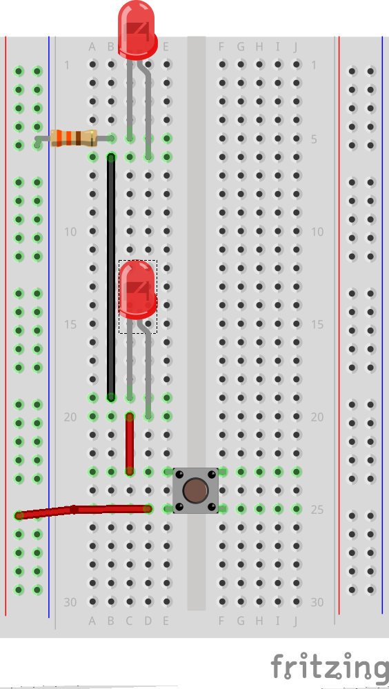
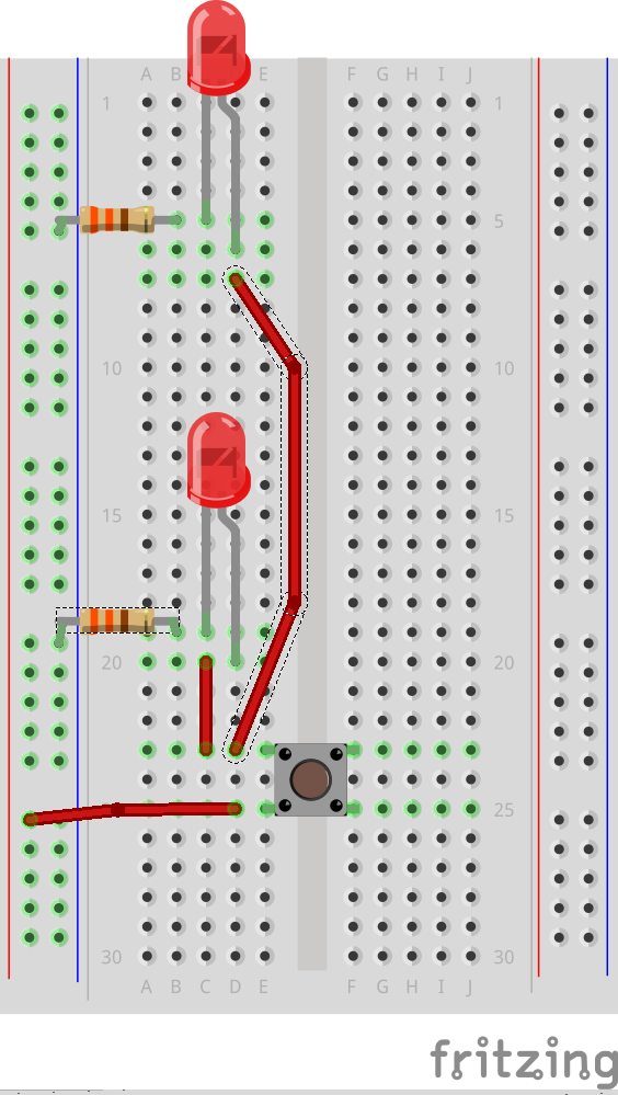
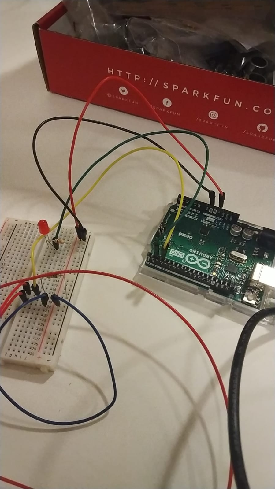
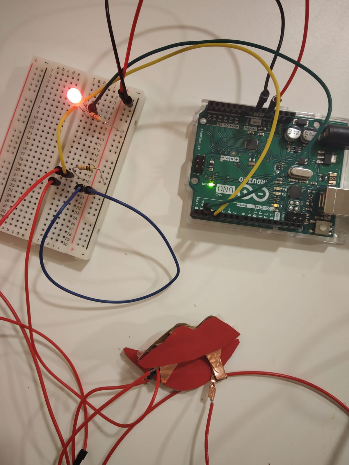
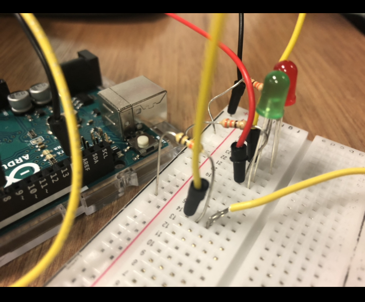
For the circuit, I have used 5 LEDs ( 4 red, 1 green), 8 wires, and one 320Ω resistor. The basic idea is that the individual waits for the green light to put his shoe on the platform, then the disinfection starts and takes 5 seconds to complete, when the green light goes on again, the individual can then remove his shoe.
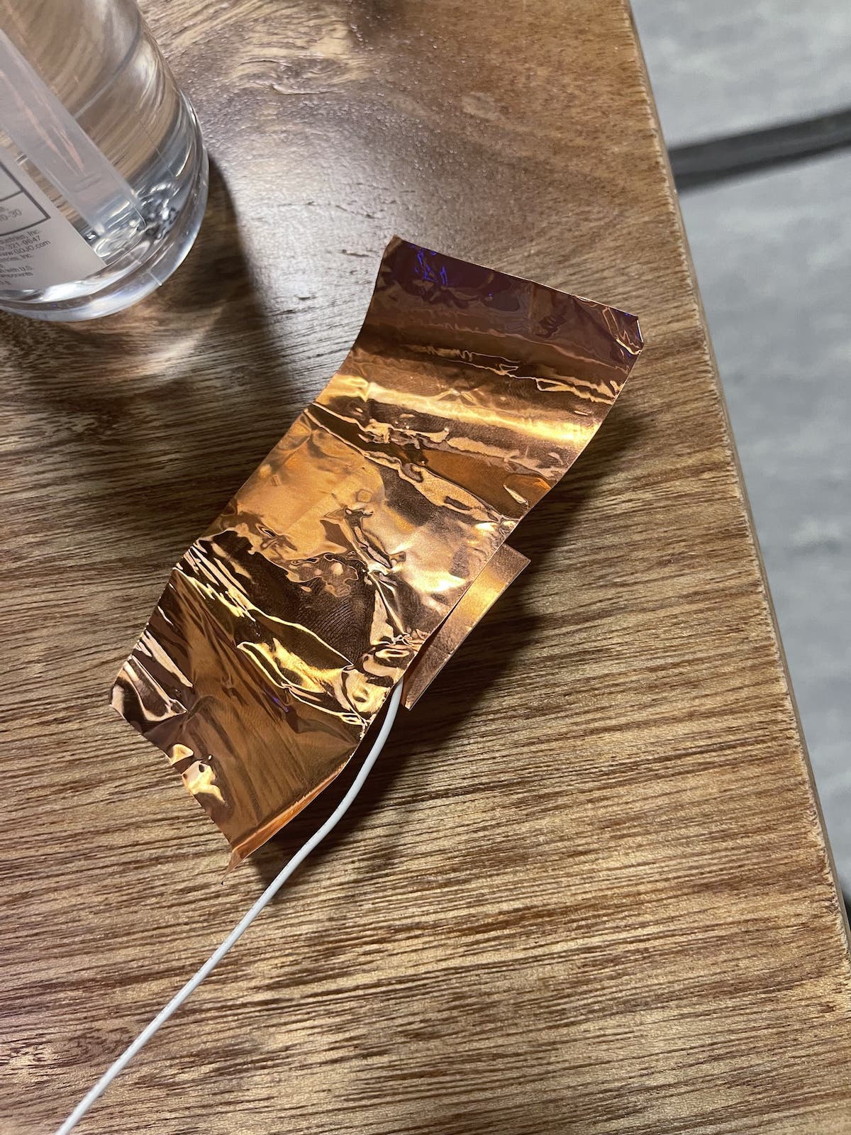
View post on imgur.com

Platform:

View post on imgur.com

Setup:

I have used a for() loop and pinMode to avoid unnecessary repetition. I also have an array to store all the LEDs.

void setup() {
  pinMode(7, OUTPUT);
  for (int i=0; i<4; i++){
    pinMode(Led[i], OUTPUT);
  }
}
LEDs:

To tell the user that the disinfection is still going on, I have added an animation to the red LEDs, in which the light bounces between the two edges of the strip. To do that, I used the Delay function as well as two for() loops (for each direction), and digitalWrite() to control the LEDs.

// Check when the shoe is sanitized
if (DONE){
  for (int i=0; i<4; i++){
    digitalWrite(Led[i], LOW);
    digitalWrite(7, HIGH);
  }
}

// If not sanitized
if (DONE==false){
  digitalWrite(7, LOW);
  // One way, left to right
  for (int i=0; i<4; i++){
    // 2 Leds at the same time
    digitalWrite(Led[i], HIGH);
    digitalWrite(Led[i+1], HIGH);
    // Delay of 120
    delay(120);
    digitalWrite(Led[i], LOW);
    digitalWrite(Led[i+1], LOW);}
  // The other way , right to left
  for (int i=3; i>=0; i--){
    digitalWrite(Led[i], HIGH);
    digitalWrite(Led[i-1], HIGH);
    delay(120);
    digitalWrite(Led[i], LOW);
    digitalWrite(Led[i-1], LOW);
  }
}
Timer:

For the timer, I have used millis() to change a boolean variable every 5 seconds.

// Timer for the sanitization
unsigned long curr = millis();
if (curr-prev>=5000){
  prev=curr;
  DONE=!DONE;
}

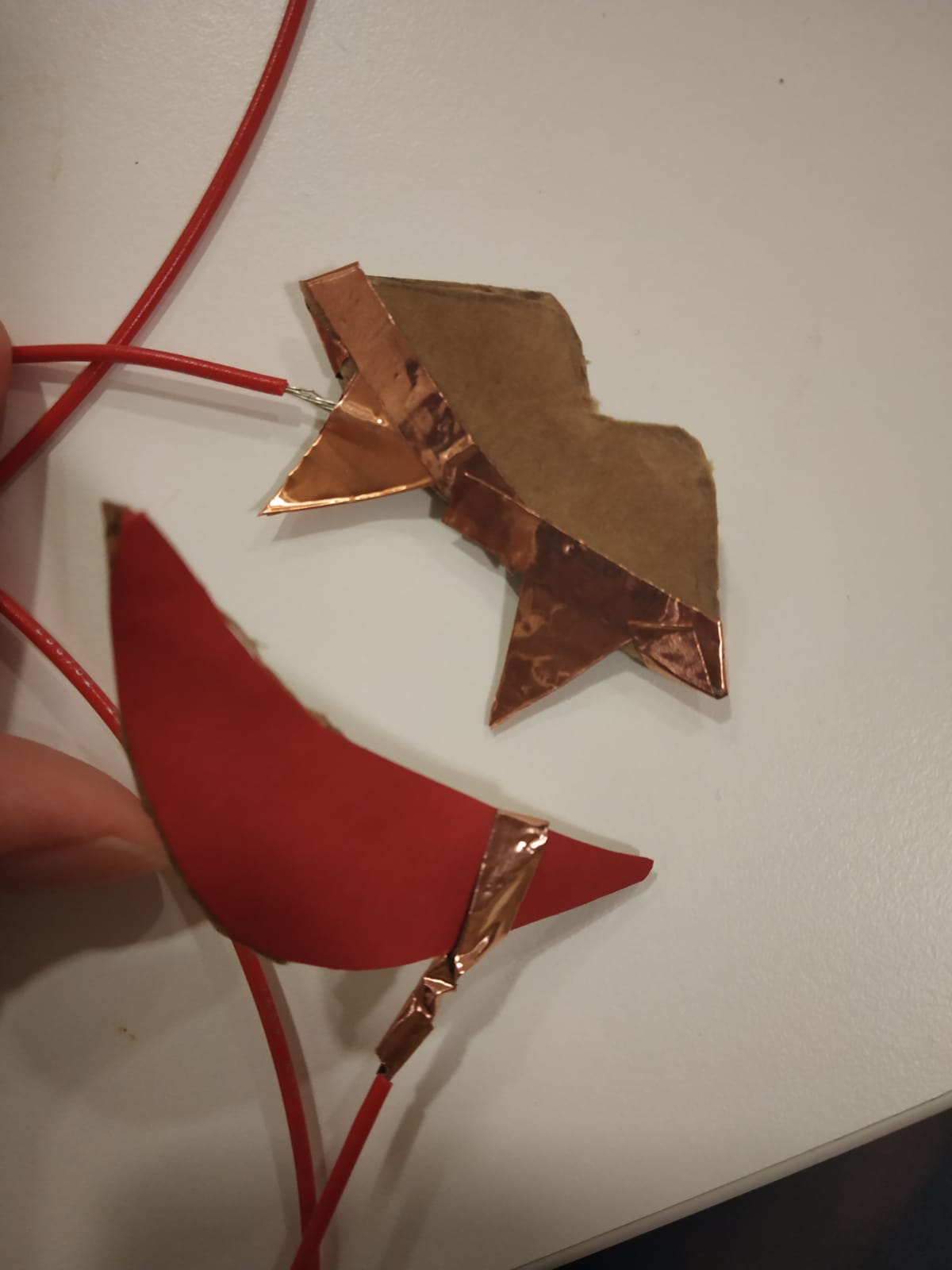
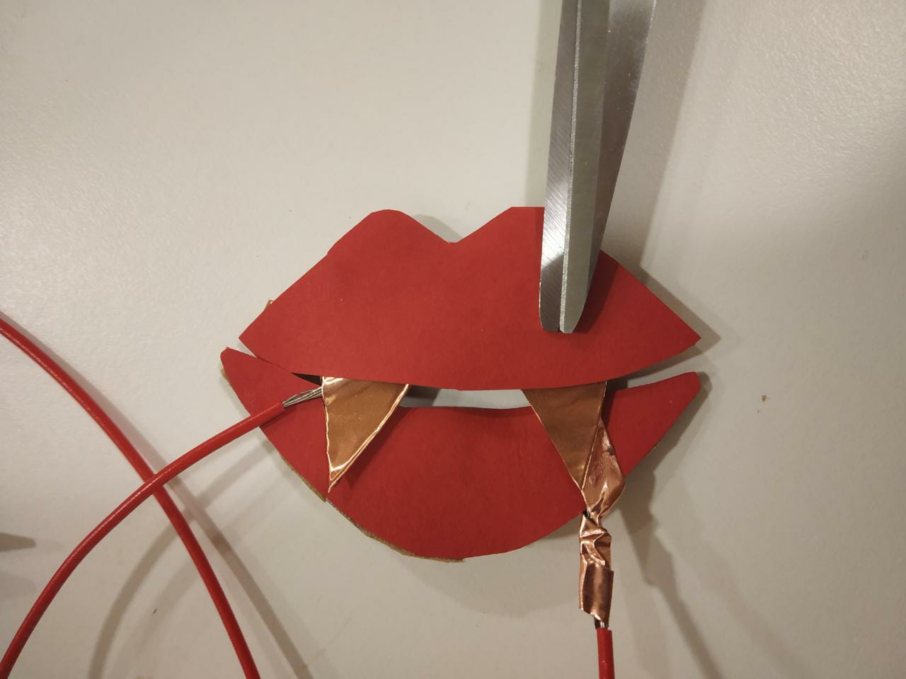
One of the challenges I faced was setting up a good connection between wires as the tape was not ideal.

Demo:

View post on imgur.com

Code:
int Led[]= {9, 10, 11, 12}; // list of Leds
boolean DONE= false; // check when the sanitization is done
unsigned long prev=0; // for the timer

void setup() {
  pinMode(7, OUTPUT);
  for (int i=0; i<4; i++){
    pinMode(Led[i], OUTPUT);
  }
}

void loop() {
  // Timer for the sanitization
  unsigned long curr = millis();
  if (curr-prev>=5000){
    prev=curr;
    DONE=!DONE;
  }
  
  // Check when the shoe is sanitized
  if (DONE){
    for (int i=0; i<4; i++){
      digitalWrite(Led[i], LOW);
      digitalWrite(7, HIGH);
    }
  }

  // If not sanitized
  if (DONE==false){
    digitalWrite(7, LOW);
    // One way, left to right
    for (int i=0; i<4; i++){
      // 2 Leds at the same time
      digitalWrite(Led[i], HIGH);
      digitalWrite(Led[i+1], HIGH);
      // Delay of 120
      delay(120);
      digitalWrite(Led[i], LOW);
      digitalWrite(Led[i+1], LOW);}
    // The other way , right to left
    for (int i=3; i>=0; i--){
      digitalWrite(Led[i], HIGH);
      digitalWrite(Led[i-1], HIGH);
      delay(120);
      digitalWrite(Led[i], LOW);
      digitalWrite(Led[i-1], LOW);
    }
  }
}


Week 8 – Sitting changes colour

Description

Create an unusual switch that doesn’t require the use of your hands. Use Arduino digital input and output for the interaction.

Process

So, I was just sitting on my chair trying to think about what to make. I got the idea, why don’t I just make something that involves sitting on the chair. So here it goes.

I used two LEDs ( red and blue). I used 3 resistors ( two 330 v and one 10k) to control the flow of electricity. I used basic conductors wires and jumper twins to finish the circuit. I connected the Red LED to Digital Input 13, Blue LED to Digital Input 12. I connected the switch to 7.

I connected the copper wires to the copper tape to give it a bigger surface area to conduct electricity.

This is the final video of me testing out the product:-

The code was pretty simple.

HERE IT GOES:-

const int ledRed = 13;
const int switch1 = 7;
const int ledBlue = 12;
bool currentState = false;
bool switchState = LOW;

void setup() {
  // put your setup code here, to run once:
  pinMode(ledRed, OUTPUT);
  pinMode(ledBlue, OUTPUT);
  pinMode(switch1, INPUT);
}

void loop() {

///put your main code here, to run repeatedly:
    switchState = digitalRead(switch1);
    if (currentState != switchState ){
      digitalWrite(ledBlue, LOW);
      digitalWrite(ledRed, HIGH);
     } else {
      digitalWrite(ledBlue, HIGH);
      digitalWrite(ledRed, LOW);
    }

}

Analog Input & Output

Potentiometer:

Inside a potentiometer:
potentiometer1.gif (472×323)

Photoresistor:

Pulse Width Modulation:
What is PWM: Pulse Width Modulation

const int ledPin = 2;
bool ledState = LOW;

// a really longer number with no + or - sign
unsigned long toggleTime = 0;
int triggerInterval = 500;

void setup() {
  pinMode(ledPin, OUTPUT);
  Serial.begin(9600);
}

void loop() {
  // read the analog input
  int knobValue = analogRead(A0);
  // map that input to a range appropriate for our use
  // in this case, we take the range of the photocell and map it to millis between 10 & 500
  // this is the blink interval for the LED
  triggerInterval = map(knobValue, 190, 860, 10, 500);

  // print out the original value and the mapped value on the same line
  Serial.print(knobValue);
  Serial.print(" ");
  Serial.println(triggerInterval);

  // if the current time (millis) is more than the exact time when we are supposed to toggle
  if (millis() > toggleTime) {
    // flip the LED to the opposite of what it was
    ledState = !ledState;
    // set the next time the LED should toggle
    // to the current time + whatever the blink interval amount of time is
    toggleTime = millis() + triggerInterval;
  }

  // turn the LED on or off based on the ledState vaviable
  digitalWrite(ledPin, ledState);
}


Arduino First Steps!

Electricity slides from class

Basic Circuits:

518c0b34ce395fea62000002.jpg (1000×669)

Series

Parallel

Button

Series with Button

Parallel with Button


Digital Read and Write:

Digital Read a button on pin 2 and digital write an LED on pin 3:

Remember to include a 330 ohm resistor for the LED and a 10k ohm pull down resistor to ground for the button.

int buttonPin = 2;
int ledPin = 3;
int ledState = LOW;
int prevButtonState = LOW;

void setup() {
  // set pin modes
  pinMode(ledPin, OUTPUT);
  pinMode(buttonPin, INPUT);
  // needed in order to start serial communication
  Serial.begin(9600);
}

// PSUEDO CODE:
// check if button is currently pressed
// if button is pressed then check to see if it was pressed during the last frame too
// (we need to remember our button state)
// if button is bressed and previous button is not pressed then flip our LED state

 void loop() {
  // check to see what state our button is in, and store that information
  int currentButtonState = digitalRead(buttonPin);

  // if the button is currently being prssed down, AND during the last frame is wasn't pressed down
  if (currentButtonState == HIGH && prevButtonState == LOW) {
      // flip the LED state
      if (ledState == HIGH){
        ledState = LOW;
      } else if (ledState == LOW){
        ledState = HIGH;
      }
  }
  // if you want to print out the LED state
//  Serial.println(ledState);

  // set our LED to turn on and off according to our variable that we flip above
  digitalWrite(ledPin, ledState);

  //we need to remember the state of our button for the next time through LOOP
  prevButtonState = currentButtonState;
}

Resistor Color Code Calculator

Week I’m Not Sure: Bloody Buttons!

The prompt for this week was to create an unusual switch which didn’t require hands, which we could use in place of the buttons we had been using in class. My initial ideas for this were either a wand touching a “Lumos” placard or a ghost figurine on a stick touching some Halloween-y thing like a Jack-o-lantern, and then the touches resulting in the LED lighting up. However, as I confirmed with Professor, these involved too direct a use of hands. I would have been directly making the object touch the other objects with my hand.

So, I had to think of a new idea, and I was feeling the Halloween spirit from my earlier idea. I decided to make that my theme. Influenced by the moustache video we saw in class, I started thinking around the mouth area and I thought I could make a switch where if the mouth is closed, the light is switched on and otherwise it’s not. I then remembered a spooky thing which goes there – a vampire’s fangs!

I had a certain image in my head and I got to work to execute it the best I could. I got cardboard and copper tape and long red wires with stranded cores from the IM lab. I didn’t want to just directly attach fangs to my lips because I wasn’t sure how safe it was, and because I thought making cartoon lips would be much more fun. So, I cut the shape of the lips out of the cardboard (one of the most time-consuming things in this project) and 4 fang shapes out of the thicker copper tape. I stuck one of the two long wires between two of these and joined the other two back-to-back too, to make it conductive on both sides. Luckily I had some red coloured paper which I could cut in the shape I wanted and paste it on the cardboard for the lips. For the bottom lip, I did this right away and then attached the required wire in its place with copper tape. It almost looked like the vampire had a lip piercing.

For the upper lip, I had to somehow connect the fangs on two ends and I didn’t want that to be visible. So I first ended up making something like this after using the thin copper tape for connection:

This was shaping up to be what I wanted it to be like, but first I thought I should test if my idea even works without red paper covering the tape. My circuit was a quite simple change from the ones we worked on in class. Instead of the button, I had two wires placed in the bread board where the legs would have been. This helped me place the resistors and other wires as required. The two wires which were replacing the button, each had their ends connected to one of the longer red wires, simply by twisting them together. So, if everything worked correctly and the right fang touched the “lip piercing”, the circuit should be complete and the LED would light up.

I had chosen the colour red because well, it reminded me of blood. And I decided that if the LED blinked when the vampire “bit” and sort of gave an alarm/heartbeat effect, it would be cool. My code combined the two main circuits we had done in Wednesday’s class. Here, LED was the output and the wire leading to the fangs was the input. When the input is HIGH, the light would start flashing at the given intervals. Otherwise, it should stop. It took me a bit of trial and error to arrive at a code which did what I wanted, but I finally got it.

const int ledPin = 2;
const int fangsPin = 3;

unsigned long timer = 0;
int timerAmount = 300;
bool flip = false;

void setup() {
  // put your setup code here, to run once:
  pinMode(ledPin, OUTPUT);
  timer = millis();
  pinMode(fangsPin, INPUT);
}

void loop() {
  // put your main code here, to run repeatedly:
  bool currentState = digitalRead(fangsPin);
  if (currentState == HIGH && millis() >= timer) {

    flip = !flip;
    digitalWrite(ledPin, flip);
    timer = millis() + timerAmount;

  }
  else if (currentState == LOW) {
    digitalWrite(ledPin, LOW);
  }

}

And this code worked with the lips I currently had, so I decided to go ahead and glue on the upper red part too. And too my relief, it worked with that too.

Lips don’t lie

A look at the overall circuit

I hope these make my circuit a bit clearer.

Then came the hardest part: Attaching these lips to my own lips. This involved a lot of tape and adjusting for the flimsiness of the whole thing. I had to make the copper wire “piercing” on the lower lip much thicker by adding more and more rounds of wire- so that it would be easier for the fang to reach. And I had to figure out the pressure and angle I should use. A couple of times by the time I went to take a video, the tape attached to my lips would wear out and I would have to redo everything. This video is not perfect- the tape was a little flimsy again so I wasn’t able to close my mouth properly for a second, but you can see that it works without me having to touch my hand to the fang- which was what was happening initially. I also realised too late that in my bid to draw something which would completely cover my real lips, I had perhaps made the lips too thick. But oh well, I wanted something cartoony anyway. They might look a little lopsided here.

I think that’s about it. Though this isn’t as smooth and perfectly artistic as I would have wanted, I’m still pleasantly surprised that the concept worked out (I don’t know what I would have done if it hadn’t).

Happy end of spooky season to y’all!

Week 8: Bicep function detector :)

Description

Create an unusual switch that doesn’t require the use of your hands. Use Arduino digital input and output for the interaction.

Process

Do your biceps work? Let’s find out! This is a switch that works using the mechanisms of your elbow. As you close your elbow the switch shows a green light, and when open it shows a red one.

So the programme requires basic coding. I use two LED lights, one red and one green, and wires to connect the flow of electricity. Using cardboard, I created two patches each to be applied on either sides of the inner side of the elbow, and put wires on each side, one going for the output (5V port)  and one for the input and taped it around my arm.

Then creating the following code where if and only if the electricity is flowing through the wire will the lights turn green, otherwise red indicating if the elbow is closed or open. Hence, showing if your biceps are working in your body or not!

CODE:

//declaring the constant variables
const int redPin = 8;
const int book = 6;
const int greenPin = 3;
bool currentState = false;
bool bookState = LOW;

void setup() {
  //determining the source function
  pinMode(redPin, OUTPUT);
  pinMode(greenPin, OUTPUT);
  pinMode(book, INPUT);
}

void loop() {
    bookState = digitalRead(book); //reading the input of book switch
    //condition to change the lights 
    if (currentState != bookState ){
      digitalWrite(greenPin, HIGH); //green on, red off
      digitalWrite(redPin, LOW);
     } else {
      digitalWrite(greenPin, LOW);//green off red on 
      digitalWrite(redPin, HIGH);
    }
}