Jade and Bhavicka’s Keys of Misery


Description / Mechanism

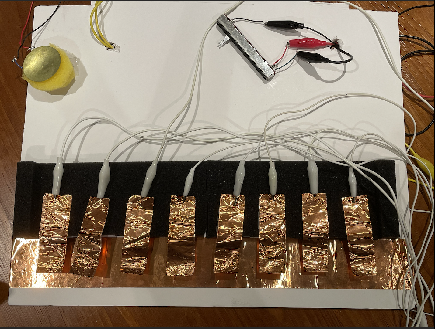
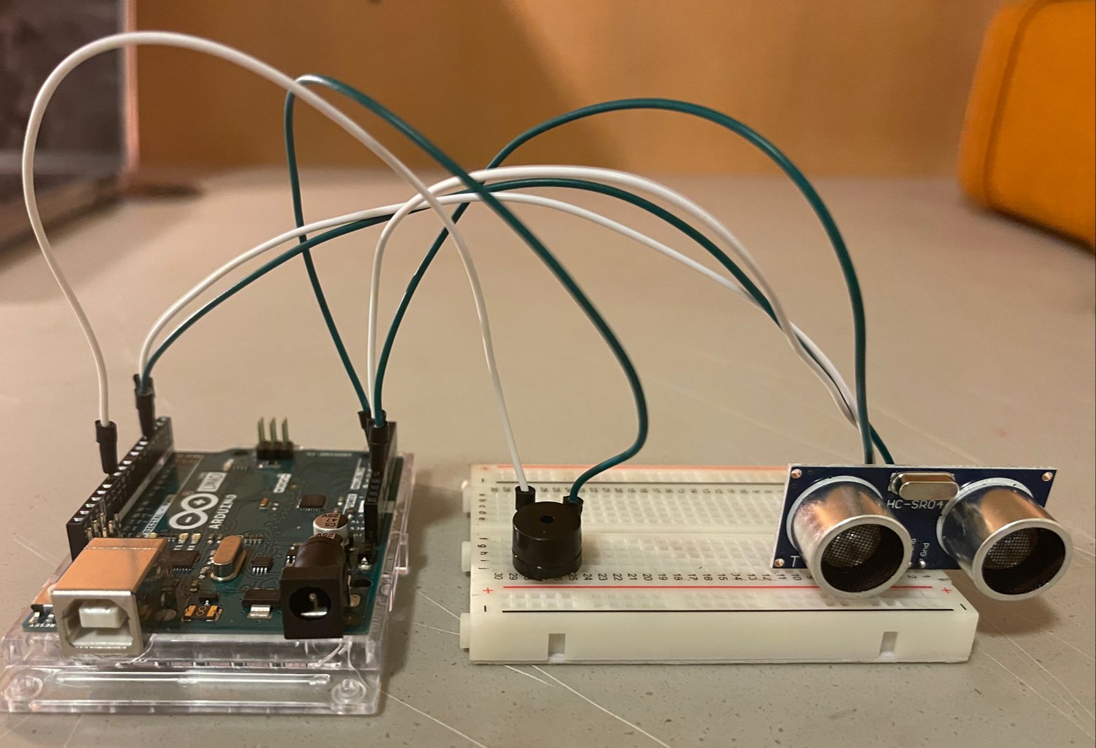
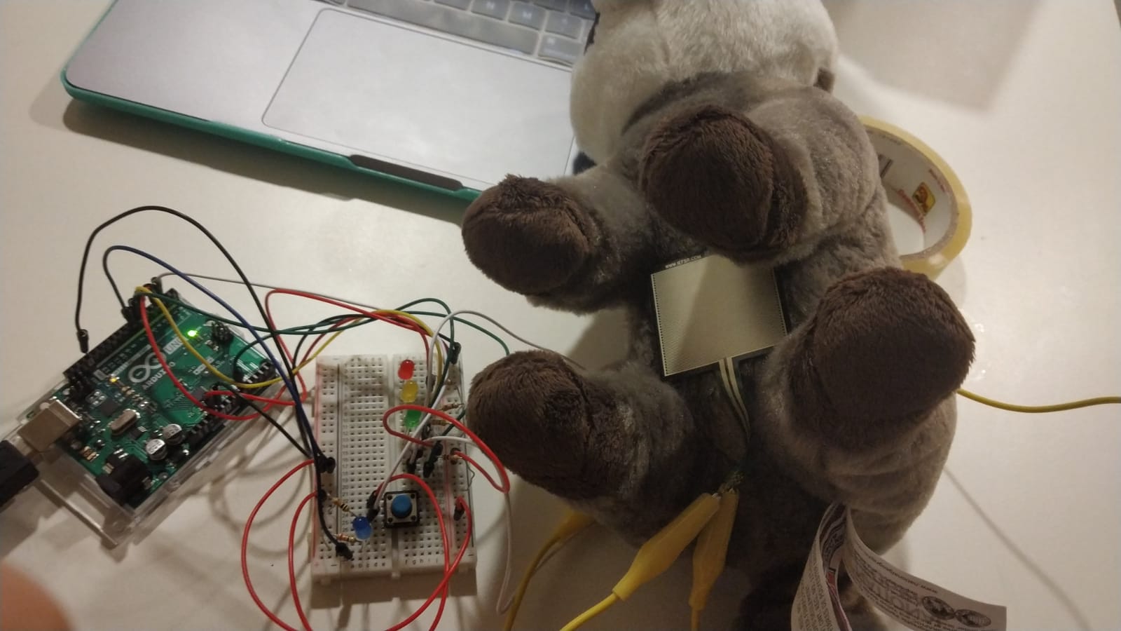
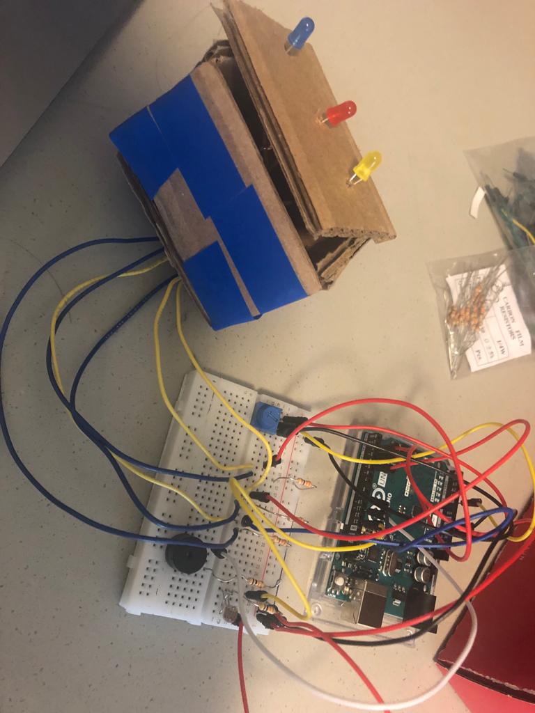
For this week, Bhavicka and I made a keyboard with a little drum around. We planned to make something like a DJ mixer, so we used the copper tapes as a keyboard, piezo as a drum and the slider as the sliding control.

At the very beginning, we thought about using MP3 shield, AD card and another speaker to play MP3 files of the sound for drum and keyboard. But it was too complicated because of all the codes that are beyond our understanding, libraries that should be installed and some compatible issues, so eventually it didn’t work out.

Then there is plan B. We used four notes for the drum sound, making it sounds like an opening theme. For the keys, we used C, D, E, F, G, A, B, C (higher) in order. The slider could change the pitch of the keys, so the pitch gets higher as we slide it to the middle and even higher when it reaches the other end.


Code

# include "pitches.h"

const int knockSensor = A0;
const int buzzer = 7;
const int slide = A1;
const int threshold = 1000;
int sensorReading = 0;
int slideReading = 0;

const int note1 = 2;
const int note2 = 3;
const int note3 = 4;
const int note4 = 5;
const int note5 = 6;
const int note6 = 8;
const int note7 = 9;
const int note8 = 10;

int drum[4] = {NOTE_C1, NOTE_C2, NOTE_C3, NOTE_C4};

int pitch0[8] = {NOTE_C3, NOTE_D3, NOTE_E3, NOTE_F3, NOTE_G3, NOTE_A4, NOTE_B4, NOTE_C4};
int pitch1[8] = {NOTE_C4, NOTE_D4, NOTE_E4, NOTE_F4, NOTE_G4, NOTE_A5, NOTE_B5, NOTE_C5};
int pitch2[8] = {NOTE_C5, NOTE_D5, NOTE_E5, NOTE_F5, NOTE_G5, NOTE_A6, NOTE_B6, NOTE_C6};

int pitch = 0;

void setup() {
  Serial.begin(9600);
  pinMode(note1, INPUT);
  pinMode(note2, INPUT);
  pinMode(note3, INPUT);
  pinMode(note4, INPUT);
  pinMode(note5, INPUT);
  pinMode(note6, INPUT);
  pinMode(note7, INPUT);
  pinMode(note8, INPUT);
}

void loop() {

  slideReading = analogRead(slide); // 562-1023
  sensorReading = analogRead(knockSensor);

  Serial.print("Knob Value: ");
  Serial.println(sensorReading);
  Serial.print("Slide Value: ");
  Serial.println(slideReading);
  
  if (sensorReading >= threshold) {
    tone(buzzer, drum[0], 200);
    delay(200);
    tone(buzzer, drum[1], 200);
    delay(200);
    tone(buzzer, drum[2], 200);
    delay(200);
    tone(buzzer, drum[3], 200);
  }

  if (slideReading <= 700) {
    pitch = 0;
  }

  else if (slideReading <= 880) {
    pitch = 1;
  }

  else {
    pitch = 2;
  }


  if (pitch == 0) {
    if (digitalRead(note1) == HIGH) {
      tone(buzzer, pitch0[0], 500);

    } else if (digitalRead(note2) == HIGH) {
      tone(buzzer, pitch0[1], 500);

    }
    else if (digitalRead(note3) == HIGH) {
      tone(buzzer, pitch0[2], 500);

    }
    else if (digitalRead(note4) == HIGH) {
      tone(buzzer, pitch0[3], 500);

    }

    else if (digitalRead(note5) == HIGH) {
      tone(buzzer, pitch0[4], 500);

    }

    else if (digitalRead(note6) == HIGH) {
      tone(buzzer, pitch0[5], 500);

    }
    else if (digitalRead(note7) == HIGH) {
      tone(buzzer, pitch0[6], 500);

    }

    else if (digitalRead(note8) == HIGH) {
      tone(buzzer, pitch0[7], 500);

    } else {
      noTone(buzzer);
    }
  }

  else if (pitch == 1) {
    if (digitalRead(note1) == HIGH) {
      tone(buzzer, pitch1[0], 500);

    } else if (digitalRead(note2) == HIGH) {
      tone(buzzer, pitch1[1], 500);

    }
    else if (digitalRead(note3) == HIGH) {
      tone(buzzer, pitch1[2], 500);

    }
    else if (digitalRead(note4) == HIGH) {
      tone(buzzer, pitch1[3], 500);

    }

    else if (digitalRead(note5) == HIGH) {
      tone(buzzer, pitch1[4], 500);

    }

    else if (digitalRead(note6) == HIGH) {
      tone(buzzer, pitch1[5], 500);

    }
    else if (digitalRead(note7) == HIGH) {
      tone(buzzer, pitch1[6], 500);

    }

    else if (digitalRead(note8) == HIGH) {
      tone(buzzer, pitch1[7], 500);

    } else {
      noTone(buzzer);
    }
  }

  else {
    if (digitalRead(note1) == HIGH) {
      tone(buzzer, pitch2[0], 500);

    } else if (digitalRead(note2) == HIGH) {
      tone(buzzer, pitch2[1], 500);

    }
    else if (digitalRead(note3) == HIGH) {
      tone(buzzer, pitch2[2], 500);

    }
    else if (digitalRead(note4) == HIGH) {
      tone(buzzer, pitch2[3], 500);

    }

    else if (digitalRead(note5) == HIGH) {
      tone(buzzer, pitch2[4], 500);

    }

    else if (digitalRead(note6) == HIGH) {
      tone(buzzer, pitch2[5], 500);

    }
    else if (digitalRead(note7) == HIGH) {
      tone(buzzer, pitch2[6], 500);

    }

    else if (digitalRead(note8) == HIGH) {
      tone(buzzer, pitch2[7], 500);

    } else {
      noTone(buzzer);
    }
  }
}


Our Process

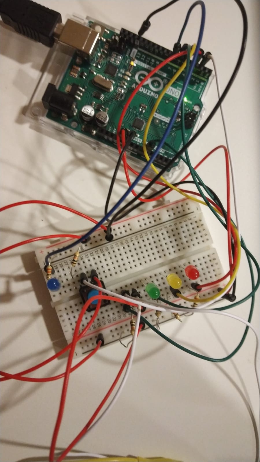
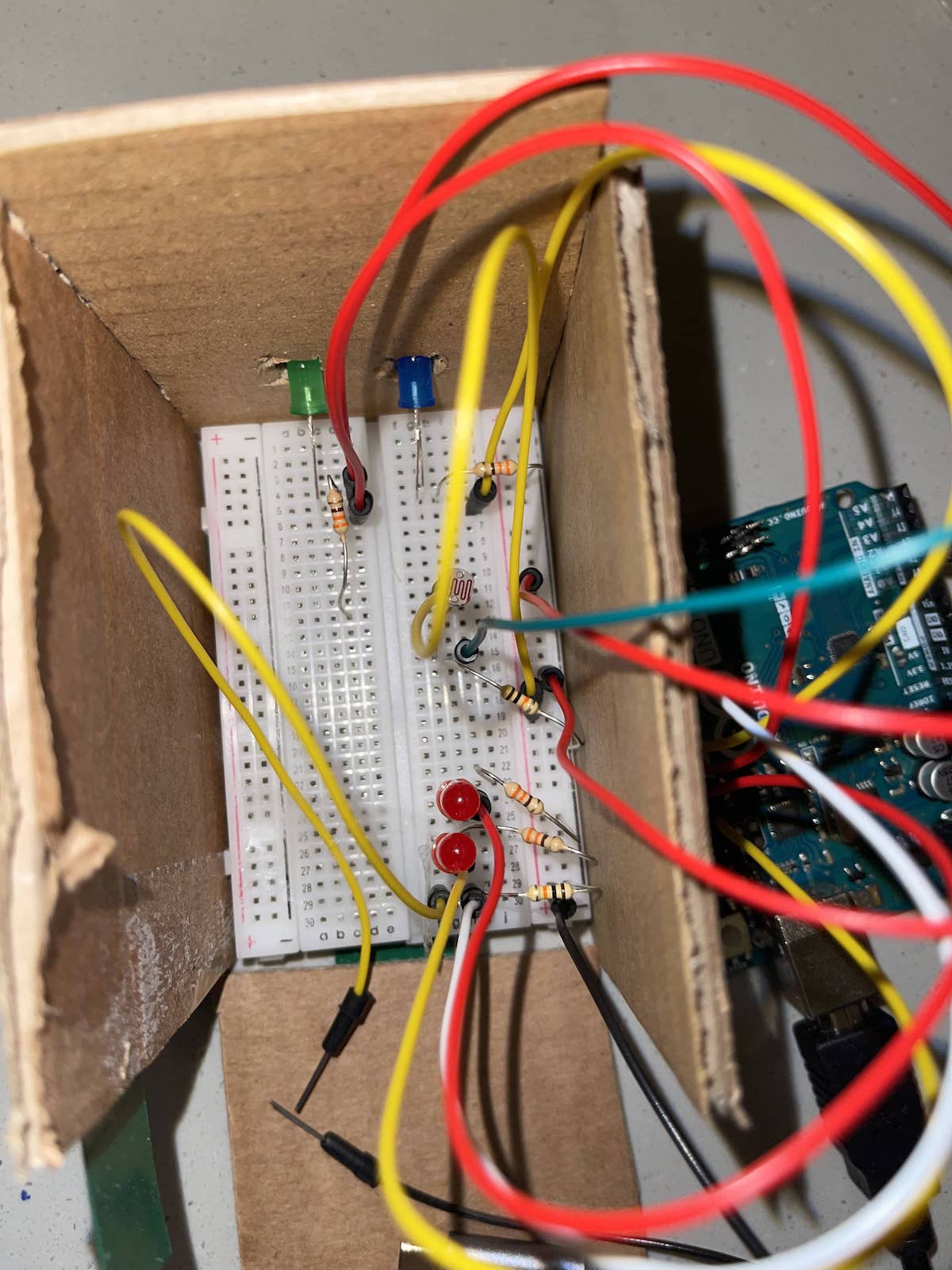
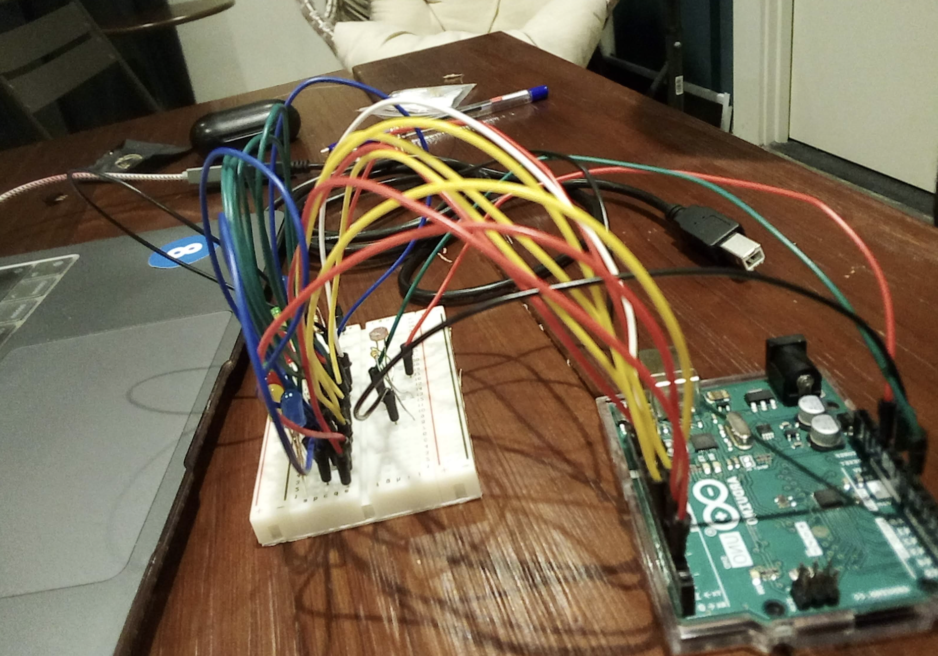
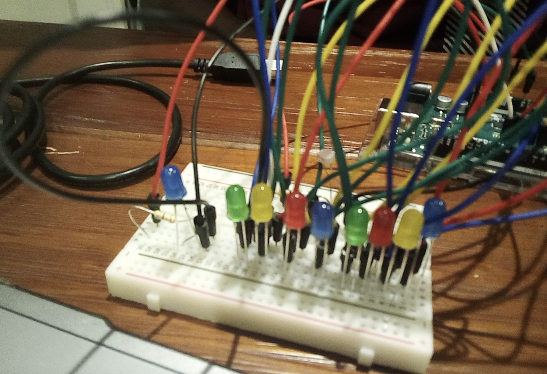
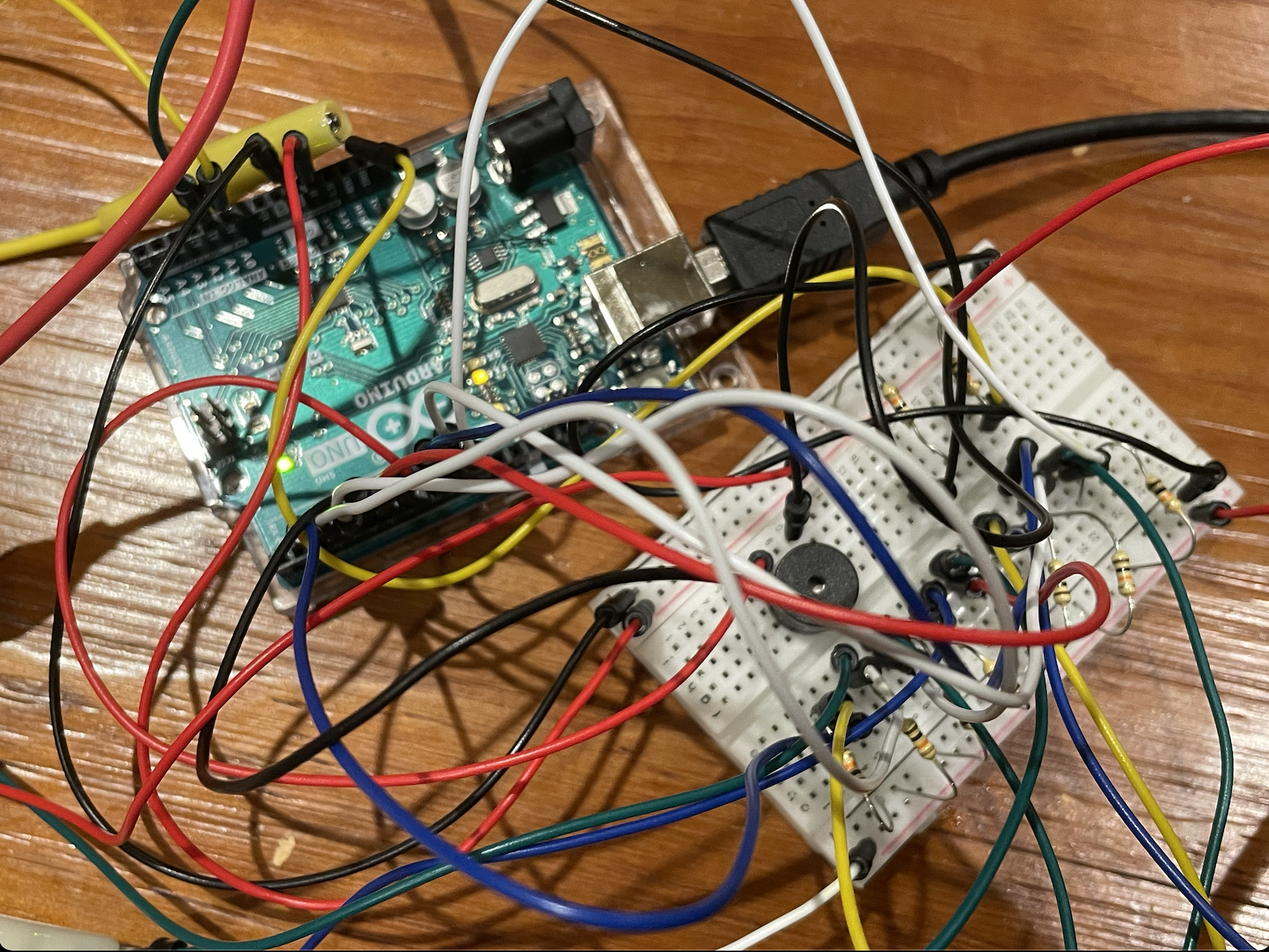
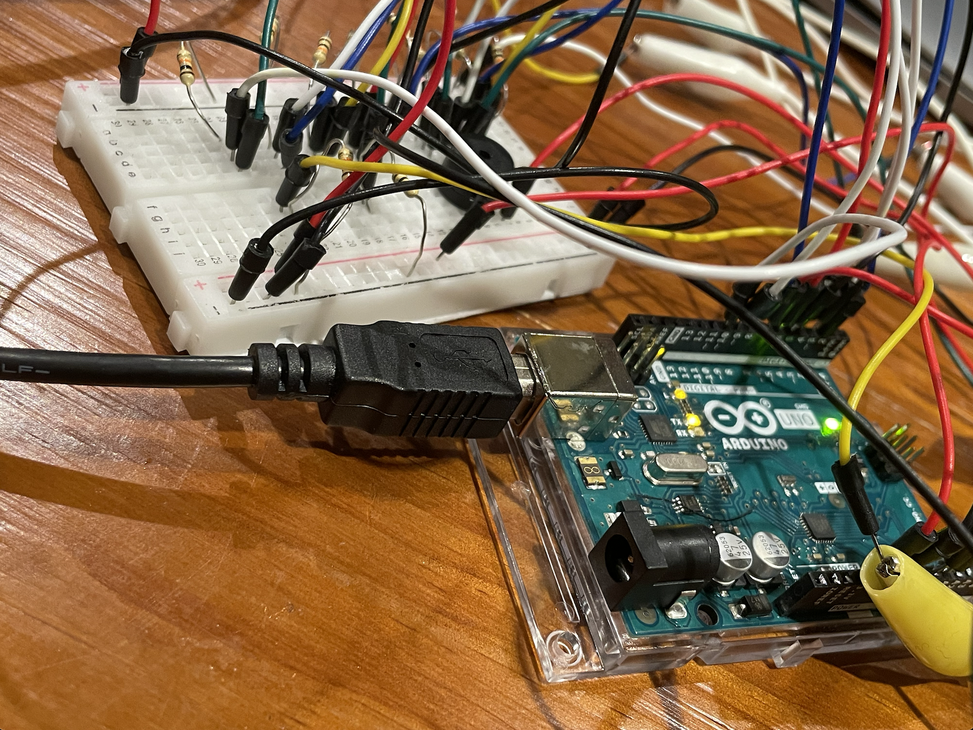
This is the most challenging project so far. We spent a lot of time figuring out the circuits as there were 8 keys, a piezo and a slider. One difficulty we encountered which took us so much time was to close the circuits for the 8 keys.

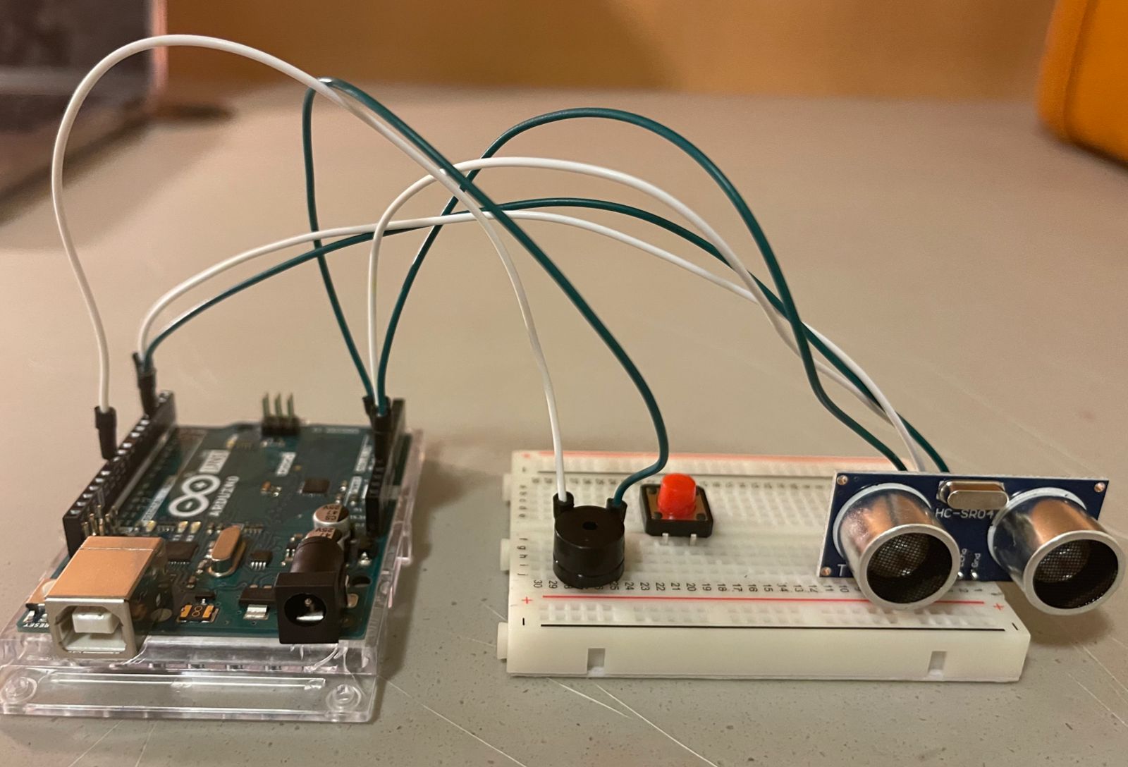
We attached a jumper cable to the copper tape below which connects to power. Then we attached other jumper cables to the keys and connected them to various pins respectively, and we also put resistors to the ground to create a switch. So when the keys touched the copper tape below, this should close a circuit.

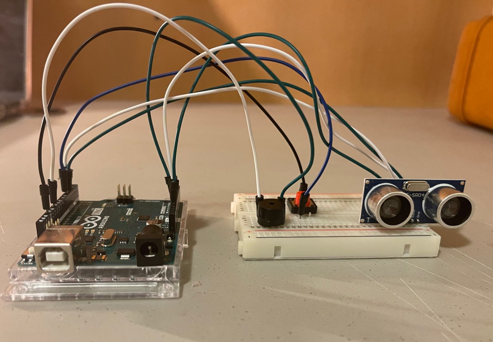
Our plan didn’t work out well at first, maybe because we put these key circuits near the circuits for the piezo and slider, which may cause a short circuit. After we moved all the cables to the other side of the bread board, the problem was solved. Since there were so many wires, we had to be really careful to not let them collide with each other, causing short circuits.

The coding part was not so challenging as the circuit part. The only problem was about the tone() and noTone() function. We realized that we should use else if condition for different notes.

else if (digitalRead(note7) == HIGH) {
 tone(buzzer, pitch0[6], 500);
 } else if (digitalRead(note8) == HIGH) {
 tone(buzzer, pitch0[7], 500);
 } else {
 noTone(buzzer);
 }

At first, we wrote the codes like:

if (digitalRead(note7) == HIGH) {
 tone(buzzer, pitch0[6], 500);
 } else {
 noTone(buzzer);
 }

if (digitalRead(note8) == HIGH) {
 tone(buzzer, pitch0[7], 500);
 } else {
 noTone(buzzer);
 }

which was problematic because when the other keys were not pressed, then noTone() was always executed. As a result, this caused the buzzer to make strange broken noise.


Although the project is demanding, the process of doing it was interesting and pleasant. The teamwork was great and it was really enjoyable working with Bhavicka!


[ Shamma – Toomie’s ] MUSICAL INSTRUMENT GROUP : Shamma’s Documentation !

SCATTERED PIANO: MUSIC IN THE AIR

WELCOME !

INTRODUCTION:

Starting off with this week's project , me and Toomie have teamed up to create an interactive music instrument, which brought us joy, and we hope you would enjoy watching it. As far as planned, our scope for what we were initially planning to do changed due to the difficulties with some of its components.  On account of that,  we had the courage to dump that idea and start all over by yesterday - a day till the deadline . Stressful ? YES. Yet we still managed to incorporate the piano in a distinct way and for that we present to you Scattered Piano - Music in the Air.

INSPIRATION:

The initial idea for our project was to create an Arduino-based piano where the notes are controlled by specific keys on the board. Yet, it didn't work. In particular, trying to get the piano keys sensor to work when we connected them with the conductive tape and wires, some keys would just work while others wouldn't. The piano, though, inspired the notion of creating music in the air using the Ultrasonic, which controls  the frequency of the buzzer according to the distance between the object and the board. The character, which I named Pianair (pian-air: piano in the air), used to denote the sounds is a toy I brought from home to provide the project with some sort of lightheartedness and cheeriness to resemble the project’s purpose.

IDEA OVERVIEW:

The idea was to interface a distance sensor or ultrasonic sensor with Arduino, measure the distance of the sensor from an obstacle and accordingly play different frequencies using the buzzer. We also used a switch to control how to turn the sensor on and off. So, we went ahead and created our musical Instrument where we can move our hand in front of the sensor and according to the distance of our hand in front of the sensor, the buzzer will play different tones. So, we can change the tone based on the distance from the sensor. A switch and led were used to indicate if our musical instrument were active or not. It was an alternate on/off logic where you can press once to turn on and press again to turn off.

PROCEDURE:

As always, our first target was to interface the distance sensor & Arduino and we gathered the following hardware for our project:
Arduino Uno R3 board with USB cable

Push Button (switch)

Breadboard

Buzzer

Jumper wires to complete the connections.

 Ultrasonic or Distance Sensor (analog to be used later)
Firstly, we just attached the ultrasonic sensor to the board. We connect it as following so that we can access all 4 pins of the ultrasonic sensor.

Next, we connected 4 wires to the ultrasonic sensor as seen. One from Vcc to 5V, other from TRIG to PIN 3 in Arduino, then echo to pin 4 in Arduino, and at last ground to ground.

Moving forward, the buzzer has been placed taking into consideration its plus and minus sides.

Then, the buzzer has been connected. We use 2 jumper wires behind the buzzer, one from the buzzer's positive side to pin 11, and the other from buzzer's negative side to ground in Arduino board.


The push button was placed in the middle where there is a split as it connects to points on a circuit when pressed. We need the two diagonal ends of the switches which are shorted once the switch is pressed.

2 extra jumper wires were placed diagonally for the push button (switch),  one end of the button to pin 5 , and the other end from button to ground in Arduino.


CHALLENGES AND PROBLEMS:


We discussed and brainstormed how can we build a unique musical instrument using sensors. Initially we thought of making a piano using conductive tape but after hours of trial and error we were unfortunately unable to complete it so we decided to build something else. Instead, we decided to use ultrasonic which is a distance sensor and a switch to make our instrument. It was very engaging to learn on how they could both work together.  

FINAL WORK:

CONCLUSION:

Overall, despite the fact that we began the project with high hopes and a determination to outperform our prior efforts, we were confronted with the harsh reality of our initial concept failing when being implemented. After a long night of trial and error, we were compelled to change our whole project in a matter of hours. But it's fine, as without trial and error, nothing comes to being. Fortunately, we came up with another concept during our brainstorming session which later came handy as we could put into action as our final idea. It was basically that we used a distance sensor to monitor the distance from an obstacle and accordingly play different tones using different frequencies in the tone() function. To show whether our musical instrument was active or not, we used a switch and the led on Arduino. What we both learned is that one shall always take their chances and trust the process with its ups and downs. Have alternatives as you never know what will go wrong. However,  don't forget that ...
AFTER EVERY STORM COMES A RAINBOW  –

FINAL CODE:

//Defined the pins 
int SW=5;// connect switch to 5
int LED=13; // connect led to 13
//Variables that are capturing the values of different parameters 
long duration, cm;
// this is to implement the switch logic 
int count;

//we initialize pins as our input and output 
void setup() 
{
  pinMode(LED, OUTPUT);// configure led as output
  pinMode(3, OUTPUT);// configure pin 3 of ultrasonic sensor as output, this is PING
  pinMode (4, INPUT);//attach pin 4 to Echo and congiure as input 
  pinMode (SW,INPUT_PULLUP);//configure switch as input, pull up resistor on to read  switch properly

  digitalWrite(LED,LOW);// led off by default
  

}

//Infinite loop which will run forever, contains main logic 

void loop()
{
  //read input from switch and store it as variable 
  bool switch_status = digitalRead(SW);

//press switch, becomes low , in other words it says switch has been pressed 

  if(switch_status == LOW)
  {
    //if we press first time, value is 1 
    count++; 
    // if switch is pressed twice , make the value go back to default which is zero  
    if(count == 2)
    {
      
      count = 0;
    }
  }

// true case if count is 1 , it means switch was pressed for first time 
  if(count == 1) // Sensor ON
  {
    digitalWrite(LED,HIGH);


  // Give a short LOW pulse beforehand to ensure a clean HIGH pulse:
  // here just sending a pulse to trigger pin in the ultrasonic 
  // the transmittor 
  
  digitalWrite(3, LOW);  delayMicroseconds(2);  
  digitalWrite(3, HIGH);  delayMicroseconds(5);  
  digitalWrite(3, LOW);

  // the recievor 
  // we calculate time taken by pulse to come back
  duration = pulseIn(4, HIGH);


  // convert the time into a distance
  //inches = microsecondsToInches(duration);
  // getting the direct value of the distance which is calculated by microsecond to centimeters  
  cm = microsecondsToCentimeters(duration);
 
 
//initialize a variable Tonetoplay

  int toneToPlay = 0;

//according to different distance, we give different values 

// Standard values , each if statemnet represents a different note on a piano 

  // different distance range from ultrasonic sensor 
  if(cm <= 160 && cm > 140)
  {
    // here it stores the frequency that will be played in hertz 
     toneToPlay = 523; 
  }
  if(cm <= 140 && cm > 120)
  {
     toneToPlay = 493; 
  }
  if(cm <= 120 && cm > 100)
  {
     toneToPlay = 440; 
  }
  if(cm > 100)
  {
    toneToPlay = 0;
  }
  if(cm <= 100 && cm > 80)
  {
     toneToPlay = 392; 
  }
  if(cm <= 80 && cm > 60)
  {
     toneToPlay = 349; 
  }
  if(cm <= 60 && cm > 40)
  {
     toneToPlay = 329; 
  }
  if(cm <= 40 && cm > 20)
  {
     toneToPlay = 294; 
  }
  if(cm <= 20)
  {
     toneToPlay = 261; 
  }
  
  if(toneToPlay == 0)
  {
    //noTone means dont generate any frequency by the sound , basically switch off the buzer 
    noTone(11);
  }
  else
  {
    //Here generate frequency of value equal to Tonetoplay
    //syntax is tone(pin, frequency, duration)
    tone(11, toneToPlay, 200);
  }
  

  }

  else if(count == 0)
  {
    digitalWrite(LED,LOW);
  }
  
  delay(250);
}


long microsecondsToCentimeters(long microseconds)
{
  // The speed of sound is 340 m/s or 29 microseconds per centimeter.
  // The ping travels out and back, so to find the distance of the
  // object we take half of the distance travelled.
  // distance is being calcualted from the time taken by pulse to come back 
  return microseconds / 29 / 2;
}


[Chi-Ting & Theyab] How to troll your friends, again, in an Arduino way

INSPIRATION

On the internet, there’s a way of making people listen to a specific song, but in a new way every time. We decided to use Arduino to do just that.

IDEA

A switch to start playing the song and stop playing the song.

A potentiometer to fasten or slow down the tempo of the song.

BREADBOARD

Here

VIDEO DEMO

CODES

int speaker_pin = 2;
bool Switch = LOW;


volatile int tone_length = 100; // determines tempo


// Parts 1 and 2 (Intro)

int melody[] =
{
  554, 622, 622, 698, 831, 740, 698, 622, 554, 622, -1, 415, 415,
  554, 622, 622, 698, 831, 740, 698, 622, 554, 622, -1, 415, 415,
  -1, 277, 277, 277, 277, 311,
  -1, 261, 233, 208,
  -1, 233, 233, 261, 277, 208, 415, 415, 311,
  -1, 233, 233, 261, 277, 233, 277, 311,
  -1, 261, 233, 233, 208,
  -1, 233, 233, 261, 277, 208, 208, 311, 311, 311, 349, 311, 277, 311, 349, 277, 311, 311, 311, 349, 311, 208,
  -1, 233, 261, 277, 208, -1, 311, 349, 311,
  466, 466, 415, 415, 698, 698, 622, 466, 466, 415, 415, 622, 622, 554, 523, 466, 554, 554, 554, 554, 554, 622, 523, 466, 415, 415, 415, 622, 554, 466, 466, 415, 415,
  698, 698, 622, 466, 466, 415, 415, 831, 523, 554, 523, 466, 554, 554, 554, 554, 554, 622, 523, 466, 415, -1, 415, 622, 554, -1,
  466, 466, 415, 415, 698, 698, 622, 466, 466, 415, 415, 622, 622, 554, 523, 466, 554, 554, 554, 554, 554, 622, 523, 466, 415, 415, 415, 622, 554, 466, 466, 415, 415,
  698, 698, 622, 466, 466, 415, 415, 831, 523, 554, 523, 466, 554, 554, 554, 554, 554, 622, 523, 466, 415, -1, 415, 622, 554, -1

};

int rhythmn[] =
{
  6, 10, 6, 6, 1, 1, 1, 1, 6, 10, 4, 2, 10,
  6, 10, 6, 6, 1, 1, 1, 1, 6, 10, 4, 2, 10,
  2, 1, 1, 1, 1, 2, 1, 1, 1, 5, 1, 1, 1, 1, 3, 1, 2, 1, 5, 1, 1, 1, 1, 1, 1, 1, 2, 1, 1, 1, 1,
  3, 1, 1, 1, 1, 2, 1, 1, 1, 1, 1, 1, 4, 5, 1, 1, 1, 1, 1, 1, 1, 2, 2, 2, 1, 1, 1, 3, 1, 1, 1, 3,
  2, 1, 1, 1, 1, 2, 1, 1, 1, 5, 1, 1, 1, 1, 3, 1, 2, 1, 5, 1, 1, 1, 1, 1, 1, 1, 2, 1, 1, 1, 1,
  3, 1, 1, 1, 1, 2, 1, 1, 1, 1, 1, 1, 4, 5, 1, 1, 1, 1, 1, 1, 1, 2, 2, 2, 1, 1, 1, 3, 1, 1, 1, 3,
  1, 1, 1, 1, 3, 3, 6, 1, 1, 1, 1, 3, 3, 3, 1, 2, 1, 1, 1, 1, 3, 3, 3, 1, 2, 2, 2, 4, 8, 1, 1, 1, 1,
  3, 3, 6, 1, 1, 1, 1, 3, 3, 3, 1, 2, 1, 1, 1, 1,  3, 3, 3, 1, 2, 2, 2, 4, 8, 4,
  1, 1, 1, 1, 3, 3, 6, 1, 1, 1, 1, 3, 3, 3, 1, 2, 1, 1, 1, 1, 3, 3, 3, 1, 2, 2, 2, 4, 8, 1, 1, 1, 1,
  3, 3, 6, 1, 1, 1, 1, 3, 3, 3, 1, 2, 1, 1, 1, 1,  3, 3, 3, 1, 2, 2, 2, 4, 8, 4,
  1, 1, 1, 1, 3, 3, 6, 1, 1, 1, 1, 3, 3, 3, 1, 2, 1, 1, 1, 1, 3, 3, 3, 1, 2, 2, 2, 4, 8, 1, 1, 1, 1,
  3, 3, 6, 1, 1, 1, 1, 3, 3, 3, 1, 2, 1, 1, 1, 1,  3, 3, 3, 1, 2, 2, 2, 4, 8, 4
};

// Parts 3 or 5 (Verse 1)


void setup()
{
  pinMode(2, OUTPUT);

  pinMode(3 , INPUT_PULLUP);

  Serial.begin(9600);

  //while (digitalRead(3));
}

void loop()
{
  Switch = digitalRead(3);
  int note_delay;

  check_pot();
  if (Switch == HIGH) {
    for (int i = 0 ; i < sizeof(rhythmn) ; i++)
    {
      if (melody[i] > 0) {

        check_pot();
        note_delay = tone_length * rhythmn[i];
        tone(speaker_pin, melody[i], note_delay);
      }
      delay(note_delay);
      delay(tone_length * 0.3);

    }
    delay(note_delay);
    noTone(speaker_pin);
  }


}

void check_pot()
{
  tone_length = map(analogRead(A0) , 0 , 1023 , 10 , 200);

}


CHALLENGES

It was a hassle trying to locate the frequencies of the notes and manipulate the duration intervals between each note.

Serial Communication

int left = 0;
int right = 0;

void setup() {
  Serial.begin(9600);
  Serial.println("0,0");
  pinMode(2, OUTPUT);
  pinMode(5, OUTPUT);
}

void loop() {
  while (Serial.available()) {
    right = Serial.parseInt();
    left = Serial.parseInt();
    if (Serial.read() == '\n') {
      digitalWrite(2, right);
      digitalWrite(5, left);
      int sensor = analogRead(A0);
      delay(1);
      int sensor2 = analogRead(A1);
      delay(1);
      Serial.print(sensor);
      Serial.print(',');
      Serial.println(sensor2);
    }
  }
}

/*

import processing.serial.*;
Serial myPort;
int xPos=0;
int yPos=0;
boolean onOff=false;
boolean onOff2=false;

void setup(){
  size(960,720);
  printArray(Serial.list());
  String portname=Serial.list()[1];
  println(portname);
  myPort = new Serial(this,portname,9600);
  myPort.clear();
  myPort.bufferUntil('\n');
}

void draw(){
  background(255);
  ellipse(xPos,yPos,30,30);
  if (mousePressed){
    if(mouseX<=width/2)
      onOff2=true;
    else
      onOff=true;
  }else{
    onOff=onOff2=false;
  }
}

void serialEvent(Serial myPort){
  String s=myPort.readStringUntil('\n');
  s=trim(s);
  if (s!=null){
    println(s);
    int values[]=int(split(s,','));
    if (values.length==2){
      xPos=(int)map(values[0],0,1023,0, width);
      yPos=(int)map(values[1],0,1023,0, height);
    }
  }
  myPort.write(int(onOff)+","+int(onOff2)+"\n");
}

 */

All serial examples: https://github.com/aaronsherwood/introduction_interactive_media/tree/master/arduinoExamples/serialExamples

  1. make something that uses only one sensor  on arduino and makes the ellipse in processing move on the horizontal axis, in the middle of the screen, and nothing on arduino is controlled by processing
  2. make something that controls the LED brightness from processing
  3. take the gravity wind example below and make it so every time the ball bounces one led lights up and then turns off, and you can control the wind from one analog sensor
PVector velocity;
PVector gravity;
PVector position;
PVector acceleration;
PVector wind;
float drag = 0.99;
float mass = 50;
float hDampening;

void setup() {
  size(640,360);
  noFill();
  position = new PVector(width/2, 0);
  velocity = new PVector(0,0);
  acceleration = new PVector(0,0);
  gravity = new PVector(0, 0.5*mass);
  wind = new PVector(0,0);
  hDampening=map(mass,15,80,.98,.96);
}

void draw() {
  background(255);
  if (!keyPressed){
    wind.x=0;
    velocity.x*=hDampening;
  }
  applyForce(wind);
  applyForce(gravity);
  velocity.add(acceleration);
  velocity.mult(drag);
  position.add(velocity);
  acceleration.mult(0);
  ellipse(position.x,position.y,mass,mass);
  if (position.y > height-mass/2) {
      velocity.y *= -0.9;  // A little dampening when hitting the bottom
      position.y = height-mass/2;
    }
}
  
void applyForce(PVector force){
  // Newton's 2nd law: F = M * A
  // or A = F / M
  PVector f = PVector.div(force, mass);
  acceleration.add(f);
}

void keyPressed(){
  if (keyCode==LEFT){
    wind.x=-1;
  }
  if (keyCode==RIGHT){
    wind.x=1;
  }
  if (key==' '){
    mass=random(15,80);
    position.y=-mass;
    velocity.mult(0);
  }
}


“RA?” Party Saver

INSPIRATION

The most dreadful thing at a party is when someone knocks on the door. The booming bass abruptly stops and people scramble to hide. Now we need someone to check while others are in their safe spots. To communicate discreetly, we need a visual indicator.

IDEa

When the button is pressed, a conspicuous red exclamation appears. Once the button is released, the bright green question mark comes back. If someone turns on the light, which is very bright compared to the dim party environment, the LED indicators brighten up to signal the message better.

BREADBOARD & ARDUINO BOARD

HERE

DEMO

CODES

bool button = LOW; 
int light = 0; 

void setup() {
  // put your setup code here, to run once:
    pinMode(7, INPUT);
  for (int i = 2; i < 14; i++) {
    pinMode(i, OUTPUT);
  }
  Serial.begin(9600);
}

void loop() {
  // put your main code here, to run repeatedly:
  button = digitalRead(7);
  light = analogRead(A0);

  int mappedLight = map(light, 0, 1023, 0, 255);
  Serial.print("Analog value : ");
  Serial.print(light);
  Serial.print(" Mapped value : ");
  Serial.println(mappedLight);
  
  if (button == HIGH) {
    for (int i = 2; i < 7; i++) {
      digitalWrite (i, HIGH); //turns on red LED
      analogWrite(i, mappedLight);
    }
    for (int j = 8; j < 14; j++) {
      digitalWrite (j, LOW);        //turns off green LED
    }
  }
  else {
    for (int i = 2; i < 7; i++) {
      digitalWrite (i, LOW);        //turns off red LED
    }
    for (int j = 8; j < 14; j++) {
      digitalWrite (j, HIGH);        //turns on green LED
      analogWrite(j, mappedLight);
    }
  }
}

CHALLENGES

Given the fact that 10 LEDs were used, the breadboard obviously look messy, which made it hard to organize. It was not simple to figure out the mistake in the circuit, but, with patience, it came out alright.

Week 9: Give Some Space to Your Soft Toys Too!

This week we had to use both analog and digital input and connect them to LEDs to give analog and digital input. When professor mentioned soft toys in class, my mind went back to my own soft toy, a small cuddly raccoon. I thought about how most people hug their soft toys, but maybe when they are in distress they might forget how much force they are actually applying and end up hurting their soft toy by squeezing too hard.

So, my idea was to use a force sensor and attach it to a soft toy, and using the analog input, either a green, yellow or red LED will slowly light up using mapped values, depending on the force values (which go from around 0 to a 1000). The digital input would be a button which would switch on a blue LED to indicate you are using the set-up. Once the red LED lights up and there’s an overload, the blue light will start blinking to get your attention so that you can stop holding your soft toy so tight.

This project took me a lot of time to complete, because I couldn’t debug it properly before the submission day (I know, I know, I did it again) and then I spent the whole of next day and night sleeping after taking a painkiller after my Pfizer booster shot. Major major thanks to Eric, who helped me figure out today why it wasn’t working and finally get the outcome I wanted. It only took a few lines of code to be changed in the end, as is usually the (very frustrating) case in coding.

The first problem I had was that the analog input wasn’t working as it should, even though I reinitialised each LED every time in the loop. This was fixed by making a function for the default (LOW) states and calling them in each if block. And then, once analog was working, the digital part suddenly didn’t light up as brightly as before but I realised that was because I had forgotten to declare the pinMode for the blue LED in the mess of copy and pasting. Apart from that, digital output mostly involved Frankensteining different bits of code from class.

Here is the code, and the comments will hopefully make it clear:

const int force = A0;
const int led1 = 3;
const int led2 = 5;
const int led3 = 6;
const int led4 = 7;
const int button = 2;
unsigned long timer = 0;
int timerAmount = 100;
bool flip = false;
bool onOff = false;
bool prevButtonState = LOW;
bool overload = false;

void setup() {
  
  Serial.begin(9600);
  pinMode(led1, OUTPUT);
  pinMode(led2, OUTPUT);
  pinMode(led3, OUTPUT);
  pinMode(led4, OUTPUT);
  pinMode(button, INPUT);
  timer = millis();
}

void loop() {
  
  int mappedValue;
  int forceValue = analogRead(force);

  Serial.print("Force value: "); //for debugging
  Serial.println(forceValue);

  //green light
  if (forceValue <= 300) {
    off();
    mappedValue = map(forceValue, 0, 300, 0, 255);
    analogWrite(led3, mappedValue);
    overload = false;
  }

  //yellow light
  else if (forceValue <= 750) {
    off();
    mappedValue = map(forceValue, 301, 750, 0, 255);
    analogWrite(led2, mappedValue);
    overload = false;
  }

  //red light
  else if (forceValue <= 1100) {
    off();
    mappedValue = map(forceValue, 751, 1000, 0, 255);
    analogWrite(led1, mappedValue);
    overload = true;
  }

  //to switch on the blue light once
  bool currentState = digitalRead(button);
  if (currentState == HIGH &&  prevButtonState == LOW) {
    onOff = !onOff;
    digitalWrite(led4, onOff);
  }

  prevButtonState = currentState;

  //to make the blue light blink when there's an overload ie the red light is on
  if (overload == true) {
    if (onOff == true && millis() >= timer) {

      flip = !flip;
      digitalWrite(led4, flip);
      timer = millis() + timerAmount;

    }
    else if (currentState == LOW) {
      digitalWrite(led4, LOW);
    }
  }
}

//default state 
void off() {
  analogWrite(led1, LOW);
  analogWrite(led2, LOW);
  analogWrite(led3, LOW);
}

Here is how the circuit works:

And here are some pictures of the circuit, along with how it looked after I attached it to my raccoon using tape:

And this is a final demonstration of how it is supposed to work:

I think that’s all, I can’t think of anything else to add here except for a thank you to Eric once again and apologies for the late post (once again)!

Emergency light

Main idea:

For this assignment, I tried to build an emergency light that automatically turns on whenever there is a power outage using both an analog sensor (LDR) and a digital sensor (switch).

Components:

x1 LDR

x1 Button push switch

x2 10K resistors

x1 350 resistor

x7 wires

View post on imgur.com

Process:

When the photoresistor’s surface (LDR) receives enough luminosity (light), its resistance decreases and is read by the program. When the values go lower than 350, it means that there was a power outage, therefore, the program turns the LED on. If the values remain higher than 350, the LED stays off and no power outage is detected.

Global variables:

I am using four global variables (3 are of data type int for the pins, and one boolean variable to check the state of the LED).

int led = 3; // LED pin 
int ldr = A0; // LDR pin 
int button = 5; // Button pin 
bool on = false; // Boolean variable for the state of the LED
Setup():

In the setup function, I mainly set the components to the pins (LED to 3, switch to 5, and LDR to A0) and set Serial.begin() to 9600.

void setup() { 
   Serial.begin(9600); 
   pinMode(led, OUTPUT); // Set the LED pinmode 
   pinMode(ldr, INPUT); // Set the LDR pinmode 
   pinMode(button, INPUT); // Set the button pinmode 
}
Loop():

To achieve the desired result, I am using analogRead() to get the luminosity’s value, then check if it is higher or lower than 350 using if/else conditions. 

// read the brightness from the ldr 
int brightness = analogRead(ldr);
// if its dark (power outage) 
if (brightness < 350) { 
   digitalWrite(led, HIGH); 
} 
// if everything is normal (light) 
else { 
   digitalWrite(led, LOW); 
}

The switch here works as an ON/OFF button for the whole process. I am using a boolean variable as well as digitalRead() to check the state of the LED.

// check if switch is clicked 
if (on == false && digitalRead(button)== HIGH){     
    on = true; 
} 
if (on == true && digitalRead(button) == HIGH){ 
   on = false; 
}

Challenges & thoughts:

To give it a realistic look, I wanted to add a delay() function after the click, and before the lights go on or off, but I wasn’t sure if it would affect the interactivity (mainly when the user clicks on the button). Therefore, I decided to avoid it.

Demo:

View post on imgur.com

Code:
int led = 3; // LED pin
int ldr = A0; // LDR pin
int button = 5; // Button pin
bool on = false; // Boolean variable for the state of the LED


void setup() {
  Serial.begin(9600);
  pinMode(led, OUTPUT); // Set the LED pinmode
  pinMode(ldr, INPUT); // Set the LDR pinmode
  pinMode(button, INPUT); // Set the button pinmode
}

void loop() {
// read the brightness from the ldr
  int brightness = analogRead(ldr);
// check if switch is clicked
  if (on == false && digitalRead(button)== HIGH){
    on = true;
  }
  if (on == true && digitalRead(button) == HIGH){
    on = false;
  }
  // if switch is clicked, then proceed 
  if (on==true){
// if its dark (power outage)
    if (brightness < 350) {
      digitalWrite(led, HIGH);
    }
// if everything is normal (light)
    else {
      digitalWrite(led, LOW);
    }
  }
  else if (on==false) {digitalWrite(led, LOW);}
}


Ford Cardboard Truck

Description:

Get information from at least one analog sensor and at least one digital sensor (switch), and use this information to control at least two LEDs, one in a digital fashion and the other in an analog fashion, in some creative way.

Process:

I first started this process, just by completing the circuit and finishing the requirements of the assignment, that is, to use a sensor (analog), button (digital switch )

I used 4 LEDs, 6 resistors ( 4 – 330 v and 2- 10k), jumper cables, LDR (Light-dependent resistor) resistors, breadboard, and Arduino board.

I used the LDR in a way in which if the surroundings are bright (more than 400 (LDR sensor status)), blue LED would light up, and if the surroundings are dark(less than 400 (LDR sensor status)), green LED would light up. By bending the lights a little and using the cardboard, I made it look like a car.

So, I used the LEDs as the front light of the truck. Then, I had to use a switch, so I did that by using the back of the truck.

So, if I closed the back of the truck, one red LED would light up, if I opened it, the other would light up.

This is what the breadboard and Arduino looked like:

This is how the LDR resistor looked like when it worked:

Overall, it was fun to use my creativity to learn how to use these tools.

The code for this is given below:

const int ledPin = 10;
const int ledPin2 = 9;
const int knobPin = A1;

const int ledRed = 13;
const int switch1 = 7;
const int ledBlue = 12;
bool currentState = false;
bool switchState = LOW;


void setup() {
  // put your setup code here, to run once:
  Serial.begin(9600);
  pinMode(ledPin, OUTPUT);
  pinMode(ledPin2, OUTPUT);
  pinMode(knobPin, INPUT);

  pinMode(ledRed, OUTPUT);
  pinMode(ledBlue, OUTPUT);
  pinMode(switch1, INPUT);

}

void loop() {
  // put your main code here, to run repeatedly:

  int ldrStatus = analogRead(knobPin);

  if(ldrStatus <= 400){
    digitalWrite(ledPin, HIGH);
    digitalWrite(ledPin2, LOW);
    
    }
    else{
      digitalWrite(ledPin, LOW);
      digitalWrite(ledPin2, HIGH);
      
      
      }

    switchState = digitalRead(switch1);
    if (currentState != switchState ){
      digitalWrite(ledBlue, LOW);
      digitalWrite(ledRed, HIGH);
     } else {
      digitalWrite(ledBlue, HIGH);
      digitalWrite(ledRed, LOW);
    }
}


Week 9: Night Musical Box!

Description 

Get information from at least one analog sensor and at least one digital sensor (switch), and use this information to control at least two LEDs, one in a digital fashion and the other in an analog fashion, in some creative way.

Process

I started with creating a box out of the cardboard, with holes on the top for the lights. Using the light sensor , I detected when the lights were out and only when it was dark would the potentiometer (knob) get power from its port, and transfer it current to different leds and the buzzer. I used 330 ohm resistor for each leds, and 10k resistor for the light sensor and the buzzer.  Here is a photo of the setup:

The output of the knob is divided between three intervals. On each interval, one light lights up , starting with the yellow led and ending at the blue one.  The buzzer too at each interval beeps at different frequencies, giving a musical note.

Here’s a video:

CODE: 

//declaring the ports
const int pot_power = 2;
const int ledyellow = 3;
const int ledred = 5;
const int ledblue = 9;
const int buzzer = 11;
const int light = 13;
const int pot = A0;

void setup() {
  // put your setup code here, to run once:
  Serial.begin(9600); // begin detecting the sensors
  //declaring role of each port
  pinMode(pot_power, OUTPUT);
  pinMode(ledyellow, OUTPUT);
  pinMode(ledred, OUTPUT);
  pinMode(ledblue, OUTPUT);
  pinMode(buzzer, OUTPUT);
  pinMode(light, INPUT);
}

void loop() {
  // put your main code here, to run repeatedly:

  int lightValue = digitalRead(light); //reading value from the light port


  if (lightValue = 1) { //condition
    digitalWrite(pot_power, HIGH);
  } else {
    digitalWrite(pot_power, LOW);
    noTone(buzzer);// switch off buzzer
  }
  delay (100);

  int potValue = analogRead(pot); // reading value of the dial
  int mappedValue = map(potValue, 0, 1023, 0, 255); //mapping it to a value compatible for LEDs
  //  Serial.println(lightValue);
  //  Serial.println(mappedValue);
  //condition
  if ( mappedValue < 85) {
    analogWrite(ledyellow, HIGH);
    analogWrite(ledred, LOW);
    analogWrite(ledblue, LOW);
    tone(buzzer, 1000);
  }
  if (mappedValue >= 85 && mappedValue < 170) {
    analogWrite(ledyellow, LOW);
    analogWrite(ledred, HIGH);
    analogWrite(ledblue, LOW);
    tone (buzzer, 1500);
  }
  if (mappedValue >= 170) {
    analogWrite(ledyellow, LOW);
    analogWrite(ledred, LOW);
    analogWrite(ledblue, HIGH);
    tone(buzzer, 2000);
  }
  delay(100);
}


Night Light

Description

 Get information from at least one analog sensor and at least one digital sensor (switch), and use this information to control at least two LEDs, one in a digital fashion and the other is an analog fashion, in some creative way.

Inspiration

LEDs usually go with a college dorm. Two good things usually happen in a college dorm – a sound sleep or a loud party. I want to recreate these two scenarios using LEDs, an analog sensor, and a digital switch.

Process

From very well mind  ,the color blue is associated with the feeling of calmness or serenity. It is peaceful, tranquil, and secure which is great for sleep. Yet as a cool color, blue can sometimes seem icy, distant, or even cold. Hence can also lower the pulse rate and body temperature- the best conditions for sleep.

I didn’t have to do research for party LED, we can agree, we are going disco and loud.

This is how the setup is going to work. A dark room will stimulate the photosensor, turning on the blue led, it’s time to sleep. However, there is a button to switch to a party mode, with a lot of colorful lights.


Final Work


Challenges

I struggled for a long time in fixing the button to control the party LEDs. I tried different positions and connections on the breadboard to make it work. I tried to draw my circuit in an Arduino simulator Tinkercad but couldn’t get the hang of it. I had a lot of wires all over the breadboard, I needed a bigger breadboard.

Code
const int knob = A0;

//button
int buttonPin = 11;
bool onOff = false;
bool prevButtonState = LOW;

//sleep
const int led = 13;


//party
const int Led2=2;
const int Led3=3;
const int Led4=4;
const int Led5=5;
const int Led6=6;
const int Led7=7;
const int Led8=8;
const int Led9=9;


int i;
int c;


void setup() {
  Serial.begin(9600);
   
 pinMode(led, OUTPUT);
 pinMode(knob, INPUT);
 pinMode(buttonPin, INPUT);


  pinMode(Led2,OUTPUT);
  pinMode(Led3,OUTPUT);
  pinMode(Led4,OUTPUT);
  pinMode(Led5,OUTPUT);
  pinMode(Led6,OUTPUT);
  pinMode(Led7,OUTPUT);
  pinMode(Led8,OUTPUT);
  pinMode(Led9,OUTPUT);

}

void loop() {

   int knobValue = analogRead(knob);
  

 if (knobValue > 300){
    digitalWrite(led,HIGH);
  }
  

  else{
    digitalWrite(led,LOW);
    }

    
 bool currentState = digitalRead(buttonPin);
  
  if(currentState == HIGH && prevButtonState == LOW){
      onOff = !onOff;
      Serial.println(onOff);
      if (onOff == true){
        digitalWrite(led,LOW);
        party();
       }

       else{
        noParty();
        }
    }

      prevButtonState = currentState;
  
}

void party(){
  
  
for(i=1;i< 100;i++)
  {
    if(i%2==0)
    {
       digitalWrite(Led2,HIGH);
       digitalWrite(Led4,HIGH);
       digitalWrite(Led6,HIGH);
       digitalWrite(Led8,HIGH);
       digitalWrite(Led3,LOW);
       digitalWrite(Led5,LOW);
       digitalWrite(Led7,LOW);
       digitalWrite(Led9,LOW);
       wait(100);
      
    }
    else
    {
      digitalWrite(Led3,HIGH);
      digitalWrite(Led5,HIGH);
      digitalWrite(Led7,HIGH);
      digitalWrite(Led9,HIGH);
      digitalWrite(Led2,LOW);
      digitalWrite(Led4,LOW);
      digitalWrite(Led6,LOW);
      digitalWrite(Led8,LOW);
      wait(100);
     
    }
  }
  for(i=0;i<100;i++)
    {
      for(c=2;c<=i/2;c++)
      {
        if(i%c==0)
        {
          digitalWrite(Led2,HIGH);
          digitalWrite(Led4,HIGH);
          digitalWrite(Led6,HIGH);
          digitalWrite(Led8,HIGH);
          digitalWrite(Led3,LOW);
          digitalWrite(Led5,LOW);
          digitalWrite(Led7,LOW);
          digitalWrite(Led9,LOW);
          wait((i*10));
         
        }
      }
      if(c>i/2)
      {
        digitalWrite(Led3,HIGH);
        digitalWrite(Led5,HIGH);
        digitalWrite(Led7,HIGH);
        digitalWrite(Led9,HIGH);
        digitalWrite(Led2,LOW);
        digitalWrite(Led4,LOW);
        digitalWrite(Led6,LOW);
        digitalWrite(Led8,LOW);
        wait((i*10));
      }
    }
  
  
  }


  void noParty(){
     digitalWrite(Led2,LOW);
       digitalWrite(Led4,LOW);
       digitalWrite(Led6,LOW);
       digitalWrite(Led8,LOW);
       digitalWrite(Led3,LOW);
       digitalWrite(Led5,LOW);
       digitalWrite(Led7,LOW);
       digitalWrite(Led9,LOW);
    
    
    }

void wait(int period){
   long time_now = millis();
    while(millis() < time_now + period){
        //wait
    }
  
}