IDEA
For this week’s instrument, I wanted to replicate one of the first musical instruments that I have ever learned: a piano. When I first learned the piano at a young age, the first few pieces of music I had learned were “Mary Had a Little Lamb” and “Twinkle Twinkle Little Stars”. Also, I added another scale to play because I remember always playing scales first as a warmup before I played any other pieces. So, I wanted to be able to replicate me playing these two pieces of music and the scale with my assignment.
MAIN DIFFICULTIES & ADJUSTMENTS
Originally, I decided to make my button be able to switch between the different pieces to play at a random order and to simply play the notes in each piece with the twist of the potentiometer.
However, I thought of a major problem which is that every time I press the button, there’s a possibility that it won’t switch to another piece of music to be played by landing on the same piece again due to the random factor. Therefore, I decided to make an index where whenever the button was pressed, it’ll add to the index with it being no greater than 2 (because there’s only three pieces of music in total, 0 being first, 1 being second, 2 being the third piece). By doing, this, I can guarantee that it will not repeat the same piece of music to be played but also let me be clearer upon what I’m going to be playing.
Another major problem I encountered was that I was unable to hear repeated notes from the piazo disk clearly most likely because the loop was causing it to be played too fast for me to clearly hear that it was two notes.
Mary Had A Little Lamb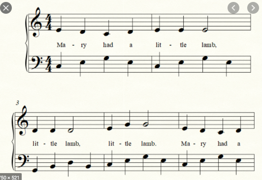 Twinkle Twinkle Little Star
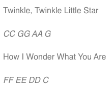
To resolve this problem, I added another button to help create the repeated notes by making it play when pressed and not when not pressed.
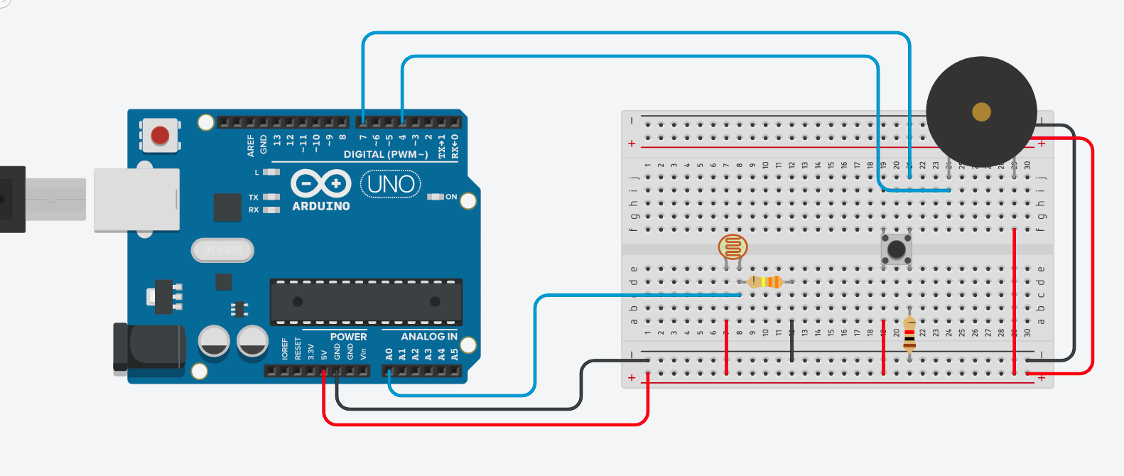
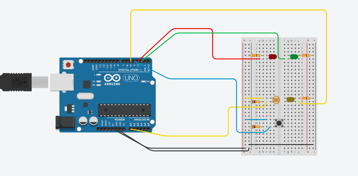
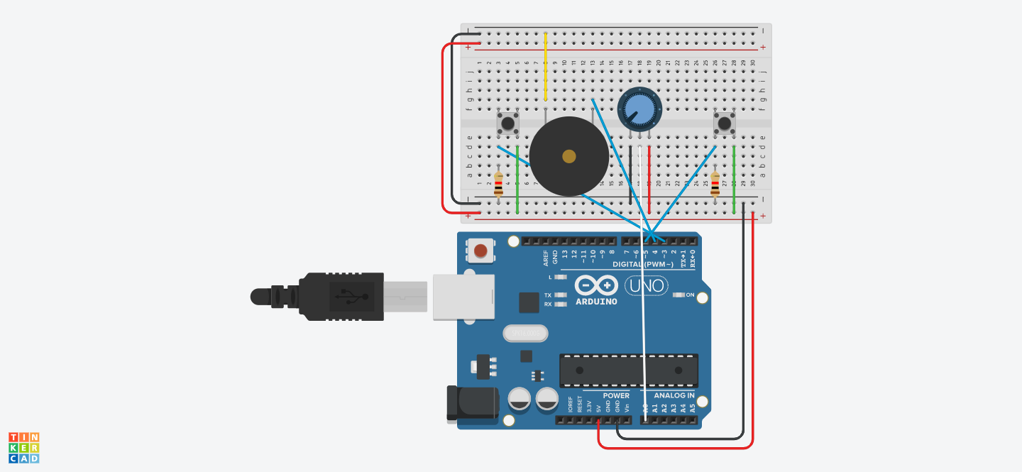
SETUP
CODE
int prevButtonState = LOW;
int randomNum;

#include "pitches.h"
// tere are 3 different sets of arrays consisting of 10 different notes
int notesIndex = 0;
int notes[3][10] = { {NOTE_C4, NOTE_D4, NOTE_E4, NOTE_F4, NOTE_G4, NOTE_A4, NOTE_B4, NOTE_C5, NOTE_D5, NOTE_E5}, {NOTE_E4, NOTE_D4, NOTE_C4, NOTE_D4, NOTE_E4, NOTE_D4, NOTE_E4, NOTE_G4 }, {NOTE_C4,NOTE_G4,NOTE_A4, NOTE_G4, NOTE_F4, NOTE_E4, NOTE_D4, NOTE_C4 }};
const int button = 5;
const int button2 =  3;
const int speaker = 4;
const int durations[10];


void setup() {
  Serial.begin(9600);
}

void loop() {
  buttonpress();
  if ( digitalRead(button2) == HIGH) {
    knobturn();
  }else{
    noTone(speaker);
  }
}

void buttonpress() { // whenever the button's pressed, it switches to a different array of notes
  int currentbuttonstate = digitalRead(button);
  if (currentbuttonstate == HIGH && prevButtonState == LOW) {
    if ( notesIndex < 2) { // if notes index is less than 2
      notesIndex++;
    } else {
      notesIndex = 0; //go back to first array of notes
    }
    //    randomNum = random(1, 4); //pick a random number between 1-3, 1 for an array of notes, 2 for another array, 3 for another array
    Serial.println(notesIndex);
  }
  prevButtonState = currentbuttonstate;
}


void knobturn() {
  int knob = analogRead(A0);
  Serial.println(knob);
  //  tone(4, notes[val]);
  //  int rate = 1000 / durations[whichNote];

  //change the values of the knob to 0 to 9, corresponding to the number of notes in the array
  if (notesIndex == 0) {
    knob = map(knob, 0, 1023, 0, 9);
    tone(speaker, notes[0][knob]);
  }
  // if random number is 2, play the notes 2 array of notes according to the knob
  if (notesIndex == 1) {
    knob = map(knob, 0, 1023, 0, 8);
    tone(speaker, notes[1][knob]);
  }

  if (notesIndex == 2) {
    knob = map(knob, 0, 1023, 0, 8);
    tone(speaker, notes[2][knob]);
  }
}

/*************************************************

 * Public Constants

 *************************************************/

#define NOTE_B0  31
#define NOTE_C1  33
#define NOTE_CS1 35
#define NOTE_D1  37
#define NOTE_DS1 39
#define NOTE_E1  41
#define NOTE_F1  44
#define NOTE_FS1 46
#define NOTE_G1  49
#define NOTE_GS1 52
#define NOTE_A1  55
#define NOTE_AS1 58
#define NOTE_B1  62
#define NOTE_C2  65
#define NOTE_CS2 69
#define NOTE_D2  73
#define NOTE_DS2 78
#define NOTE_E2  82
#define NOTE_F2  87
#define NOTE_FS2 93
#define NOTE_G2  98
#define NOTE_GS2 104
#define NOTE_A2  110
#define NOTE_AS2 117
#define NOTE_B2  123
#define NOTE_C3  131
#define NOTE_CS3 139
#define NOTE_D3  147
#define NOTE_DS3 156
#define NOTE_E3  165
#define NOTE_F3  175
#define NOTE_FS3 185
#define NOTE_G3  196
#define NOTE_GS3 208
#define NOTE_A3  220
#define NOTE_AS3 233
#define NOTE_B3  247
#define NOTE_C4  262
#define NOTE_CS4 277
#define NOTE_D4  294
#define NOTE_DS4 311
#define NOTE_E4  330
#define NOTE_F4  349
#define NOTE_FS4 370
#define NOTE_G4  392
#define NOTE_GS4 415
#define NOTE_A4  440
#define NOTE_AS4 466
#define NOTE_B4  494
#define NOTE_C5  523
#define NOTE_CS5 554
#define NOTE_D5  587
#define NOTE_DS5 622
#define NOTE_E5  659
#define NOTE_F5  698
#define NOTE_FS5 740
#define NOTE_G5  784
#define NOTE_GS5 831
#define NOTE_A5  880
#define NOTE_AS5 932
#define NOTE_B5  988
#define NOTE_C6  1047
#define NOTE_CS6 1109
#define NOTE_D6  1175
#define NOTE_DS6 1245
#define NOTE_E6  1319
#define NOTE_F6  1397
#define NOTE_FS6 1480
#define NOTE_G6  1568
#define NOTE_GS6 1661
#define NOTE_A6  1760
#define NOTE_AS6 1865
#define NOTE_B6  1976
#define NOTE_C7  2093
#define NOTE_CS7 2217
#define NOTE_D7  2349
#define NOTE_DS7 2489
#define NOTE_E7  2637
#define NOTE_F7  2794
#define NOTE_FS7 2960
#define NOTE_G7  3136
#define NOTE_GS7 3322
#define NOTE_A7  3520
#define NOTE_AS7 3729
#define NOTE_B7  3951
#define NOTE_C8  4186
#define NOTE_CS8 4435
#define NOTE_D8  4699
#define NOTE_DS8 4978
FINAL PRODUCT (how do I include the youtube video?)