
Intro
Brainstorming for this week was pretty tough. I went from playing around with the potentiometer and ultrasonic sensor to choosing to prioritize adding signifiers and things that add more context to a project. I personally think I could’ve done something more complex or experimented more with sensors, but by the time I reached this realization I was in too deep in this assignment. However, I will make it a goal to explore the sensors and switches I still haven’t touched in the kit (temperature sensor, photoresistor, and switch).
Note: check this link for a good starting point on Ultrasonic Sensors:
Idea
After brainstorming and trying to find inspiration, I decided to make use of the potentiometer’s movement in a circular motion and wanted to do something that has to do with the user needing to point the arrow of the potentiometer towards a specific thing to get a specific interaction.
So, the potentiometer was my source of analog input.
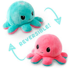
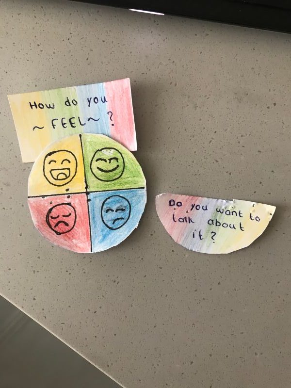
For this, I recalled the feeling charts I used to have in kindergarten, as well as the reversible octopus plushie that took over TikTok. Both these things are tools meant to make it easier for children to express their emotions without having to struggle through verbalizing it.
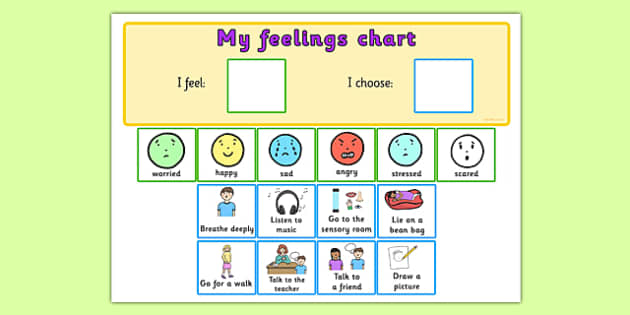
So, I thought it would be interesting to do something similar. The user inputs their feeling by twisting the dial to a certain quadrant in a circle cutout that I added to my circuit. An LED to the emotion lights up. Then, for the digital input and output, I used a simple button and LED, and the user turns on the LED if they feel like they want to talk further about why they feel the way they feel.
Implementation
In terms of the code, it was actually pretty simple. I just read through the values that the knob gives on the serial monitor, and added ranges for each LED to turn on accordingly. So, for the yellow quadrant of the circle the range was 220 – 186, and so if the user turns it and the reading is in that range, the yellow LED turns on and the rest turn off. As for the digital part, I just applied the switch example we looked over in class.
Here’s a demo:
(Okay, I did actually film horizontally, I’m not exactly sure why the video still turned out like this 🙁 (help))
Reflection and Development
I really enjoy the aspect of adding a story or context to what I’m making, it somehow makes the process much easier and I enjoyed doing that here. However, I do think I could’ve gone for something a bit more complex to push myself and really get comfortable with working with analog inputs. I think one of the main issues I have in this program is that the varying of brightness in the LED lights doesn’t make much sense in context, and I want to look into how to use elements of analog output for my benefit and to enrich my ideas. Any suggestions or insight is appreciated as always :-)!
Code
//define variables for button and LEDs
int button = 2;
int yellowLed = 11;
int greenLed = 10;
int blueLed = 9;
int redLed = 6;
int expressionLed = 3;

//booleans to check if the button is pressed + to turn LED on (digital)
bool prevButtonState = LOW;
bool expressionLedState = false;

//determining knob input for the dial
int knob = A0;

void setup() {
  pinMode(yellowLed, OUTPUT);
  pinMode(greenLed, OUTPUT);
  pinMode(blueLed, OUTPUT);
  pinMode(redLed, OUTPUT);
  pinMode(button, INPUT);
  pinMode(expressionLed, OUTPUT);
  Serial.begin(9600);
  // put your setup code here, to run once:

}

void loop() {
  // put your main code here, to run repeatedly:
  int knobValue = analogRead(knob);
  int mappedValue = map(knobValue, 0, 1023, 0, 220); //i thought mapping to 220 rather than 255 could be helpful, since my circle has 4 divisions, but it didn't make much of a difference.


  if (mappedValue >= 186) { //first quadrant, very happy
    analogWrite(greenLed, 0);
    analogWrite(blueLed, 0);
    analogWrite(redLed, 0);
    analogWrite(yellowLed, mappedValue);

  }
  else if (mappedValue <= 185 && mappedValue >= 105) { //second quadrant, happy
    analogWrite(yellowLed, 0);
    analogWrite(blueLed, 0);
    analogWrite(redLed, 0);
    analogWrite(greenLed, mappedValue);

  }
  else if (mappedValue <= 104 && mappedValue >= 22) { //third quadrant, neutral
    analogWrite(greenLed, 0);
    analogWrite(yellowLed, 0);
    analogWrite(redLed, 0);
    analogWrite(blueLed, mappedValue);

  }
  else if (mappedValue <= 21 && mappedValue >= 0) { //fourth quadrant, sad
    analogWrite(greenLed, 0);
    analogWrite(yellowLed, 0);
    analogWrite(blueLed, 0);
    analogWrite(redLed, mappedValue);
    if (mappedValue <= 5){
      analogWrite(redLed, mappedValue + 5); //to avoid light turning off
    }

  }
  //digital, turns on an LED if the individual presses it
  int buttonState = digitalRead(button);
  if(buttonState == HIGH && prevButtonState == LOW){
  expressionLedState = !expressionLedState;
  }
  digitalWrite(expressionLed, expressionLedState);
  prevButtonState = buttonState;


  //analogWrite(led,mappedValue);
//  Serial.print(knobValue);
//  Serial.print(" ");
//  Serial.println(mappedValue);

}