
As an analogy to mixing different colors when painting, I created a circuit that allows the user to use the buttons to “paint” the attached LED light.
One RGB LED is controlled by three buttons, representatives of the 3 primary colors – red, yellow and blue. There are 3 additional LED-s, a red, a yellow and a blue, that indicate which buttons are pressed, that is, which colors are used to create the color displayed by the RGB LED.
To be able to controll the LEDs, I set up the breadboard and the RedBoard as follows:
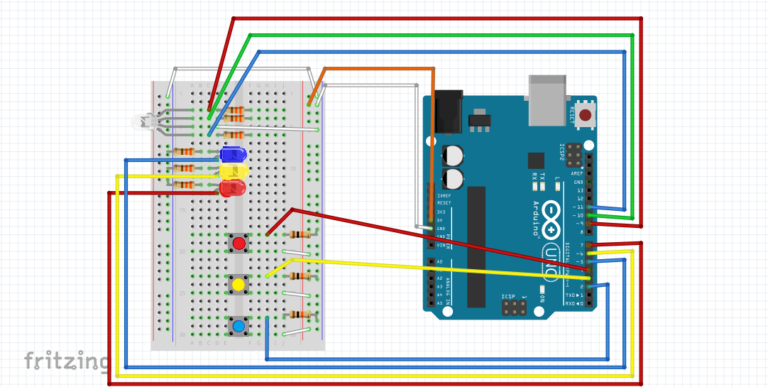
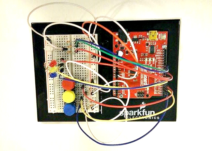
As it can be seen, there are 6 output and 3 input signals. Three of the outputs belong to the red, green and blue pins of the RGB LED, the other three belong to the red, yellow and blue LED-s, and the three inputs belong to the 3 buttons (one to each).
When setting up the boards, I was surprised to find that the buttons would not work if the input wires are connected to the board between power and one leg of the button (as shown in the SIK (Sparkfun Inventor’s Kit) Guide book on page 38), only if it is connected to the board between the other leg of the button and ground. I still do not know why, but this was the only way of ensuring that the input signal is ‘LOW’ when the button is not pressed and is ‘HIGH’ when it is pressed (when the wires were set up as shown in the guide, it seemed to work the other way round).
My Arduino program was largely based on the example on pages 29-32 of the SIK Guide (to which the code can be found here). In this example, the “basic” colors (red, green, blue, yellow, cyan, purple and white) were obtained by setting the RGB pins of the RGB LED either high or low. For instance, as can be seen in my final code, blue would be:
digitalWrite(RED_PIN, LOW);
digitalWrite(GREEN_PIN, LOW);
digitalWrite(BLUE_PIN, HIGH);
In my final code, green, red and white were obtained using the same method. However, purple, orange and yellow were obtained using the command ‘analogWrite()’. As I was able to observe in the ‘showRGB()’ method created in the SIK Guide’s example, analogWrite can mix different intensities of red, green and blue (not only “low” (0) or “high” (255) ). Thus, orange, for example, can be obtained from the code:
analogWrite(RED_PIN, 255);
analogWrite(BLUE_PIN, 0);
analogWrite(GREEN_PIN, 20);
Notes: 1, I decided to create purple and yellow this way instead of using digitalWrite() because the colors obtained that way were not distinguishable from blue and orange easily enough. 2, Even though in real life, the mixture of red, yellow and blue would not result in white, I did not want the response to the simultaneous use of the three buttons to be darkness, so I decided to make the RGB LED white at that time. 3, I added a blinking effect to the RGB LED for fun.
The other three outputs were connected to the anode of the red, yellow and blue LED-s. These were made to light up using digitalWrite(x, HIGH) each time the corresponding buttons were pressed, to indicate which colors are being used to create our mixture. A video of the working project can be seen here; the colors light up in the following sequence: blue, yellow, red, orange, green, purple, white (unfortunately, this cannot be seen very well in the video).