
Concept
Embark on an exciting treasure hunt adventure in a mystical world filled with hidden riches and formidable foes. In this immersive game, you’ll take on the role of either a skilled hunter or a stealthy ninja, depending on your taste.
Your quest begins in a green plain, where ancient treasures lie scattered, waiting to be discovered. However, time is of the essence, as you’ll have a limited duration to uncover the hidden treasures . Utilize your character’s agility and the radar to navigate through the treacherous terrain, avoiding obstacles and evading any lurking dangers.
As you progress through, the challenge intensifies. In level 2, you’ll find yourself navigating through a desolated space, where slimes, slimy creatures with a voracious appetite, roam freely. These formidable foes will stop at nothing to impede your treasure-hunting endeavors, so you’ll need to stay vigilant and employ strategic maneuvers to outmaneuver them.
To aid you in your quest, you’ll have access to a powerful radar system. By activating the radar, you’ll receive visual cues indicating the proximity of nearby treasures. However, use this ability judiciously, as it has a limited cooldown period, during which you’ll be vulnerable to potential threats.
Will you have what it takes to overcome the obstacles, outsmart the slimes, and emerge victorious with a bountiful collection of treasures? Prepare yourself for an adventure like no other, where quick reflexes, strategic thinking, and unwavering determination will be the keys to your success.
Immerse yourself in this captivating treasure hunt, where every step brings you closer to uncovering the secrets of a long-forgotten civilization. Embrace the thrill of the chase, and let your adventurous spirit guide you through this extraordinary journey.
Implementation
Interaction design:
In terms of interaction design, I had to consider two types of interaction, use interaction with the game, and the interaction between the arduino board the p5js. In terms of the serial communication, arduino sends 4 different values: buttonX, buttonY, positionX and positionY of the thumb joysticks. In the P5js code, the readSerial function splits and trims the incoming data, and each of the variables assigned to the respective incoming value. As for the p5js part, it sends the detected value, which then controls the led.
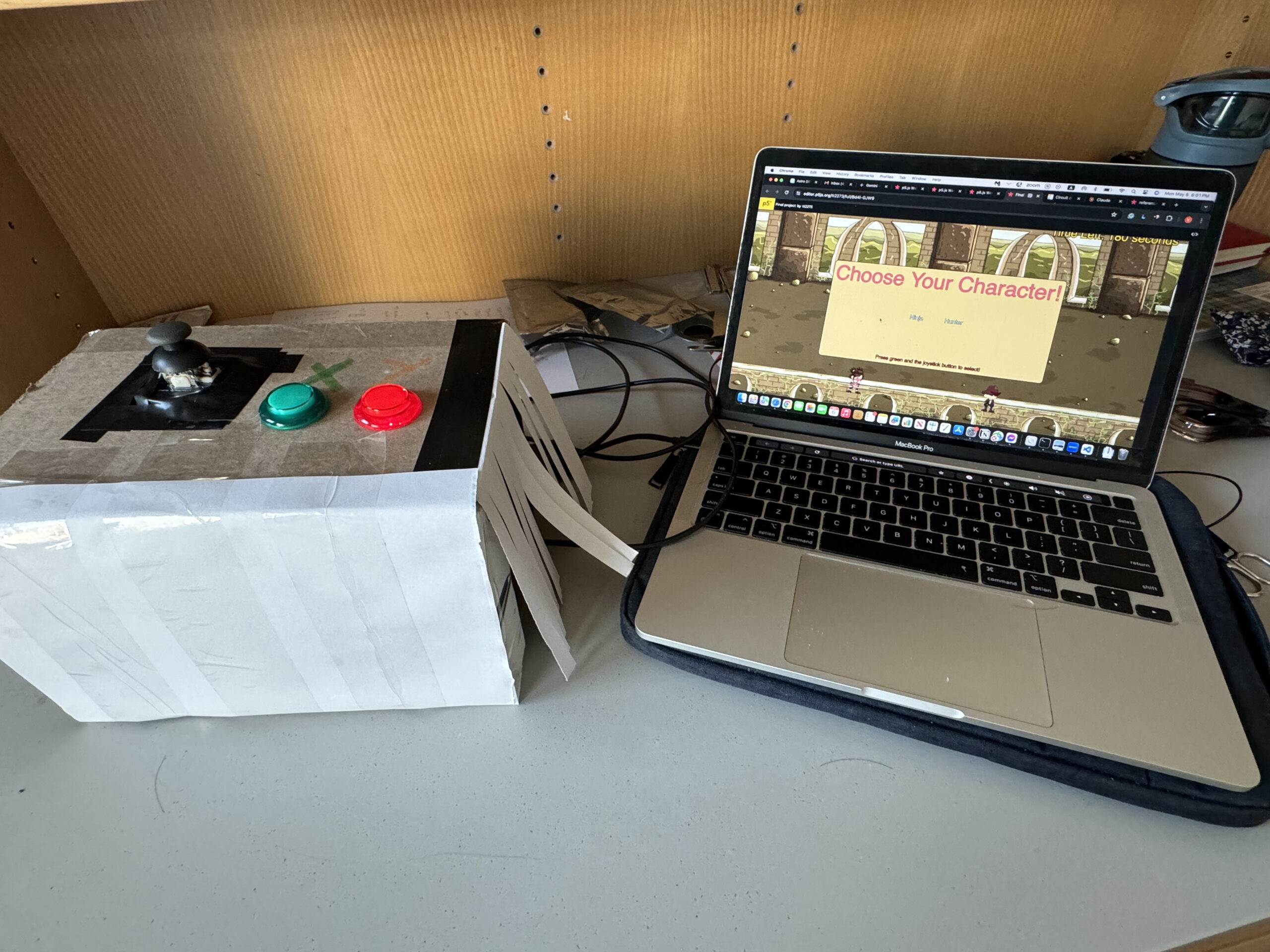
As for user interaction, I attempted to make the instructions as clear and concise as possible, but even then there were certain aspects of the game that were slightly vague. Inside the game, the user goes through 3 instruction panel, one introducing the game and stating the objectives, second one showing the remote controller instructions and the third one between the 2 levels that explains the content of level 2. Then there are 2 options waiting for the user for winning and losing condition. Furthermore, there is another panel after instructions that allows the user to choose from two given characters. Within the game states, there were also elements of interaction that were needed, for instance to represent the cooldown of the radar, I made a pulsing effect that only starts when the radar is in cooldown. Also, when the character is in contact with the slime, their animation changes for a brief second to let the user know they are defeated. When the treasure is found, it will stay on the map for brief period of time and then vanishes, increasing the counter.
P5JS Code:
P5js code is where the main game mechanics are implemented. Firstly, in the preload function, I had to load the sprites, sound, background picture and slime array. In the setup function, I configured the hunter, ninja and the slime sprites’ animations and other necessary changes. In the draw function, there are multiple game states such as intro, choose, level1, between, level2, win, and lose. Moreover, there are several helper functions at the bottom part of the code, the helps with the in game mechanics.
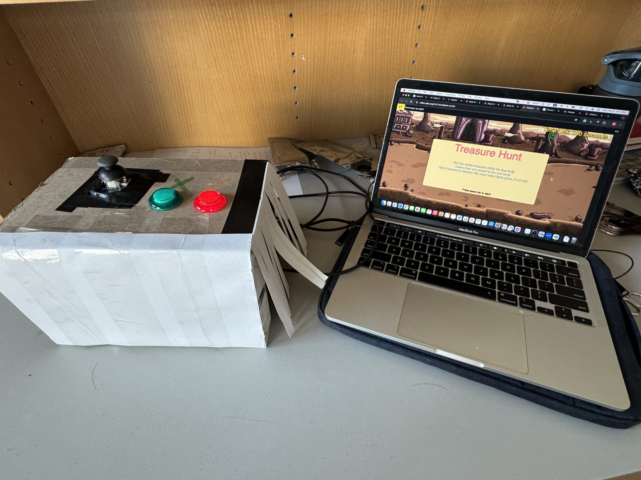
- Game State “intro”:
- Displays the background image (bg1).
- Shows the title “Treasure Hunt” and a description of the game with instructions on how to play.
- Prompts the user to press the space bar to start the game.
- Game State “instructions”:
- Displays the background image (bg2).
- Shows the title “Instructions” with details about controls (joystick for movement, green button for confirmation, red button for radar activation with cooldown).
- Prompts the user to press enter to continue.
- Game State “choose”:
- Displays the background image (bg3).
- Presents the options to choose a character between “Ninja” and “Hunter” and how to select (using the green button and joystick button).
- Allows the player to choose a character by moving the joystick and pressing the green button.
- Transitions to “level2” if a character is selected.
- Game State “level1”:
- Displays the background image (bg4).
- Updates the timer and displays the remaining time.
- Spawns treasure chests and updates the treasure count based on collected treasures.
- Handles character movement and treasure detection based on the chosen character (Ninja or Hunter).
- Updates the game state to “between” when all treasures are collected.
- Game State “between”:
- Displays the background image (bg3).
- Presents a transition message to indicate the start of the next level (“Level2”).
- Waits for the player to click to continue and transitions to “level2” when clicked.
- Game State “level2”:
- Displays the background image (bg1).
- Resets the timer and displays the remaining time for the new level.
- Spawns new treasure chests and updates the treasure count based on collected treasures.
- Handles character movement, treasure detection, and enemy interactions (slimes).
- Updates the game state to “win” if all treasures are collected or to “lose” if the timer runs out or the character is attacked by slimes.
- Game State “win”:
- Displays the background image (bg2).
- Stops the game’s background sound.
- Congratulates the player on winning, displays the time taken, and prompts to restart by clicking the green button.
- Game State “lose”:
- Displays the background image (bg3).
- Stops the game’s background sound.
- Informs the player of losing and prompts to restart by clicking the green button.
P5js Code Snippet:
if (chosenCharacter === "ninja"){
      hunterSprite.position.x = -200;
      updateSprite(ninjaSprite, "walk", 2);//function that enables the movement of sprite
      removeFoundTreasure(ninjaSprite, treasures);//function that removes the found treasures
      if (buttonY && canDetectTreasure) {
        detected = checkSurroundingForTreasure(ninjaSprite);
        canDetectTreasure = false; // Disable treasure detection for cooldown
        setTimeout(() => canDetectTreasure = true, 3000); // Enable detection after 3 seconds
  }
    } else if (chosenCharacter === "hunter"){
      ninjaSprite.position.x = -200;
      updateSprite(hunterSprite, "walk", 2);
      removeFoundTreasure(hunterSprite, treasures);
      if (buttonY && canDetectTreasure) {
        detected = checkSurroundingForTreasure(hunterSprite);
        canDetectTreasure = false; // Disable treasure detection for cooldown
        setTimeout(() => canDetectTreasure = true, 3000); // Enable detection after 3 seconds
  }
    }
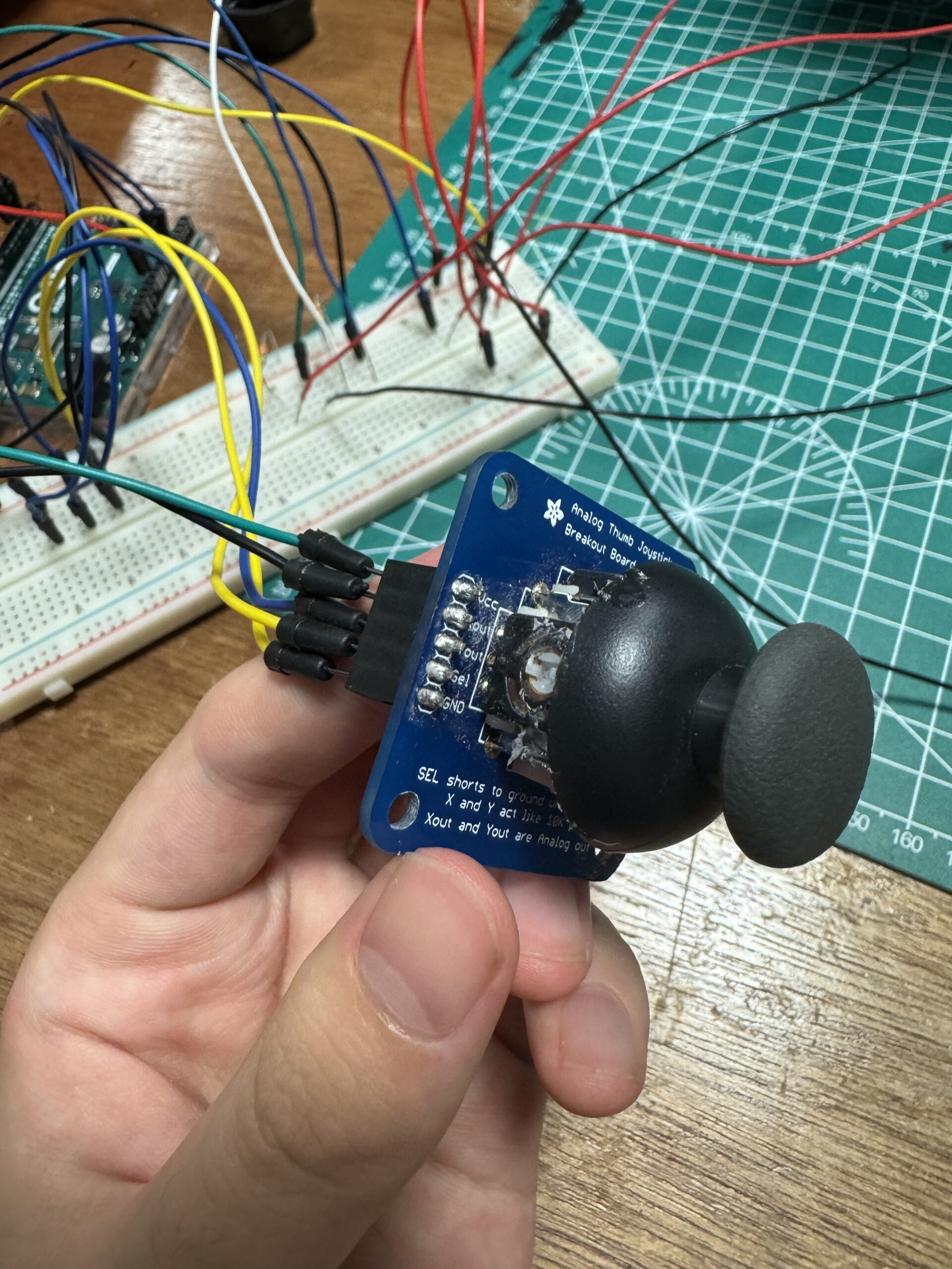
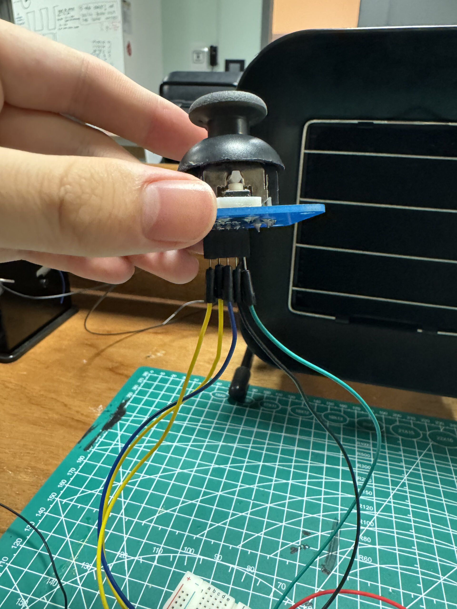
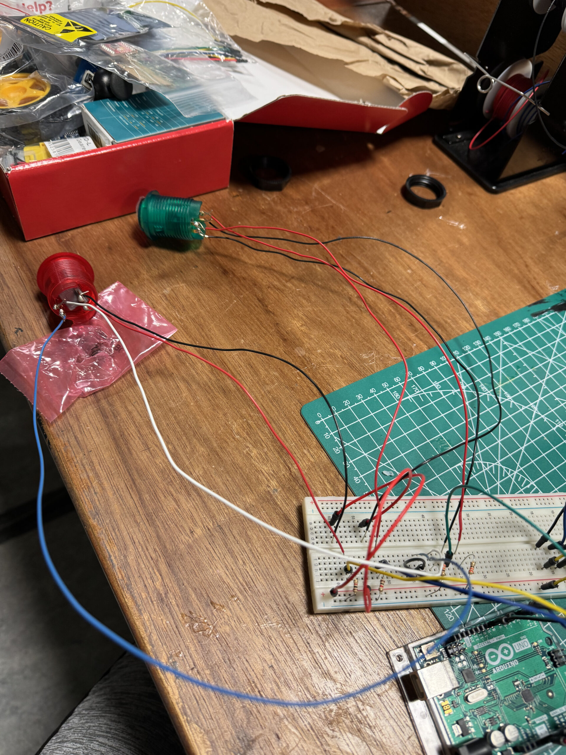
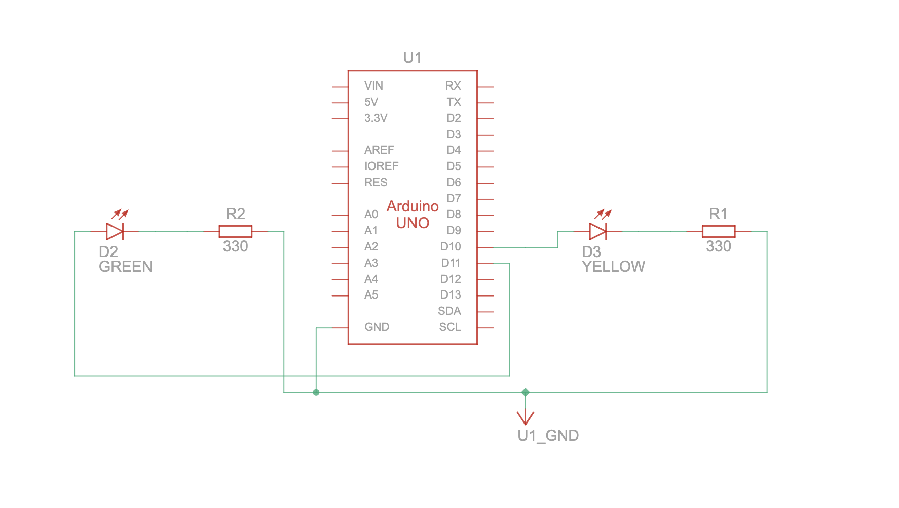
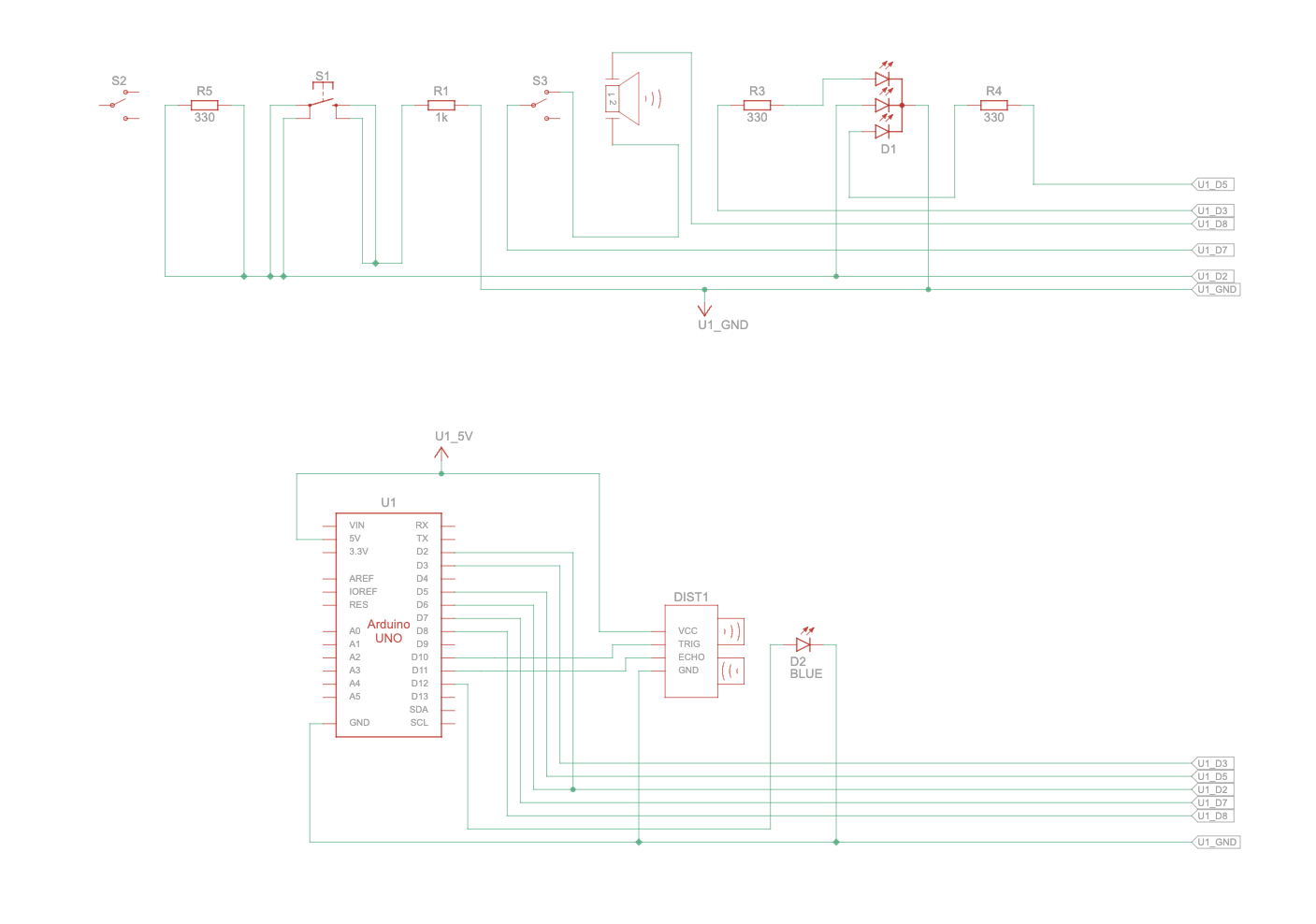
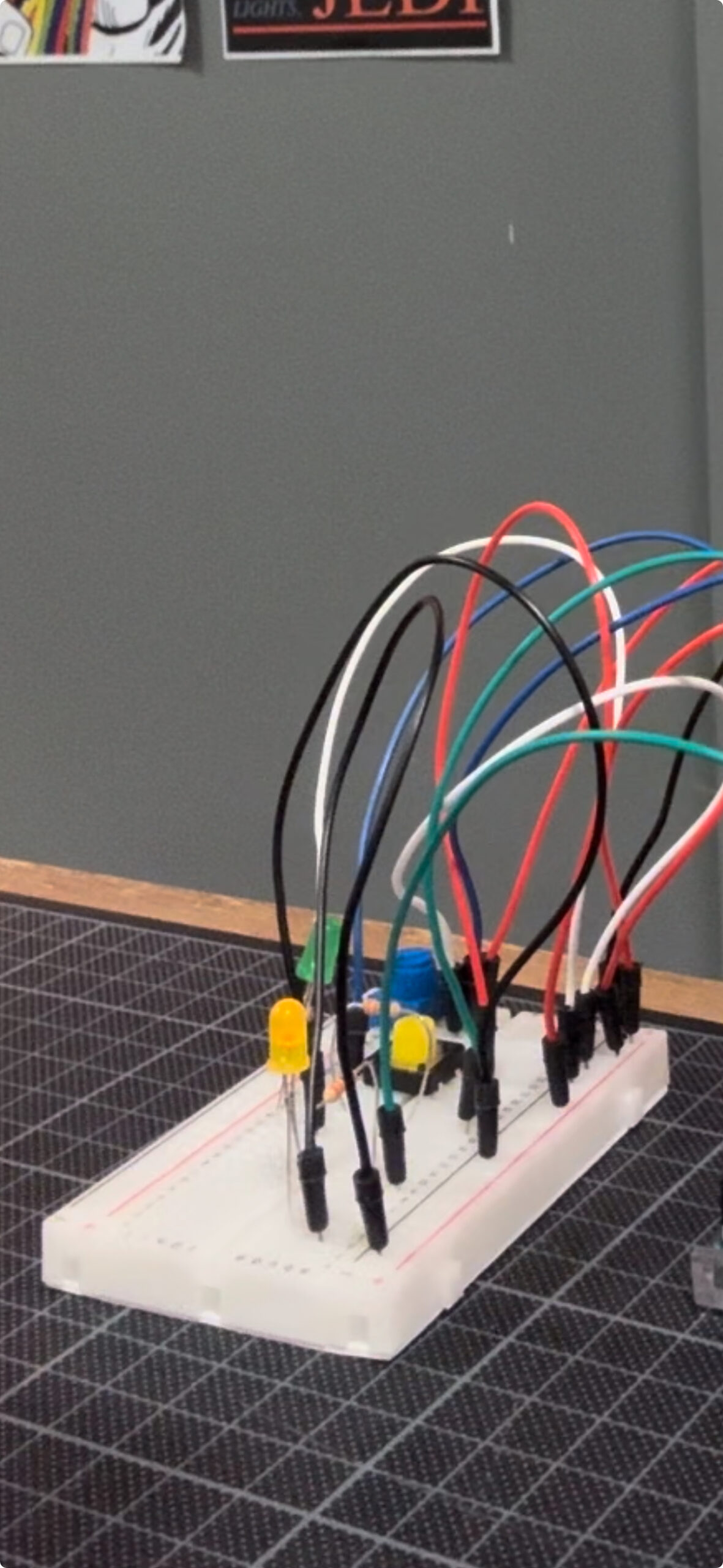
Arduino:
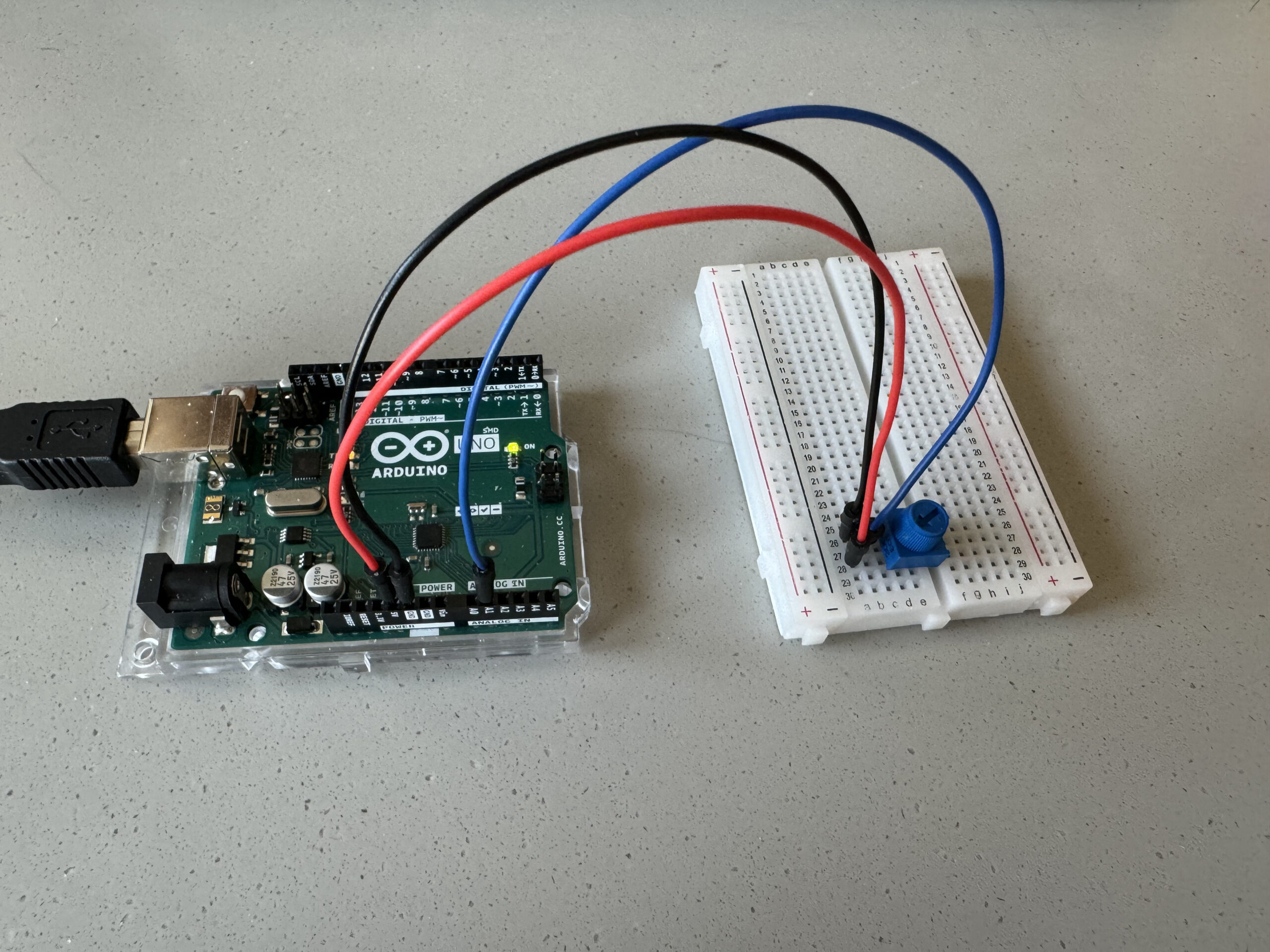
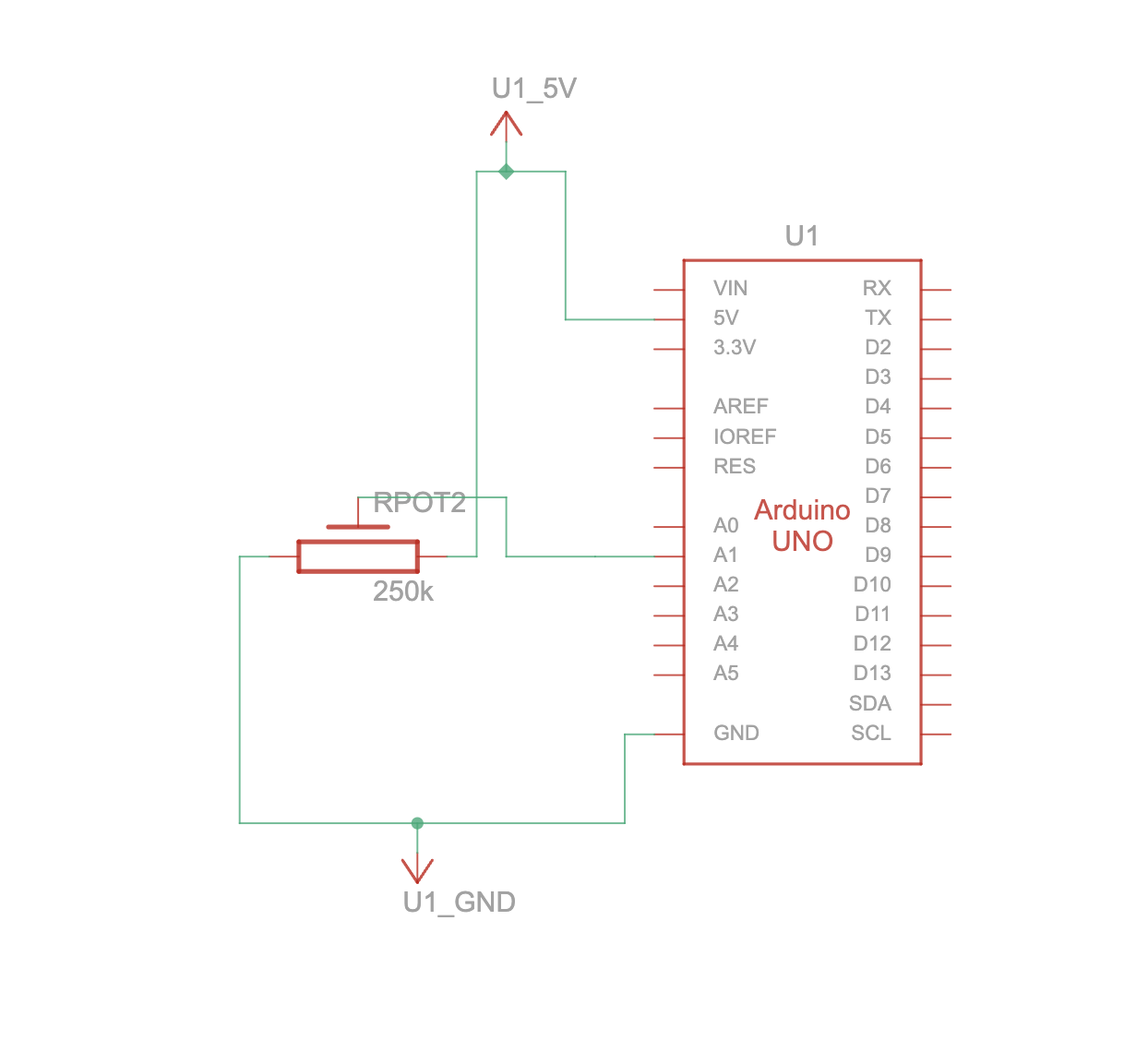
The Arduino code sets up a system to interface with a thumb joystick, two buttons with LED indicators. The pins for these components are defined at the beginning: `D_pin` for the joystick switch, `Y_pin` for the Y output of the joystick, and `X_pin` for the X output. Two digital pins, `button1Pin` and `button2Pin`, are designated for the buttons, while `gledPin` and `rledPin` are used for green and red LEDs, respectively. In the setup function, the pins are configured accordingly – `D_pin` is set as an input for the switch, and the LED pins are set as outputs. Additionally, the serial communication is initialized at a baud rate of 9600.
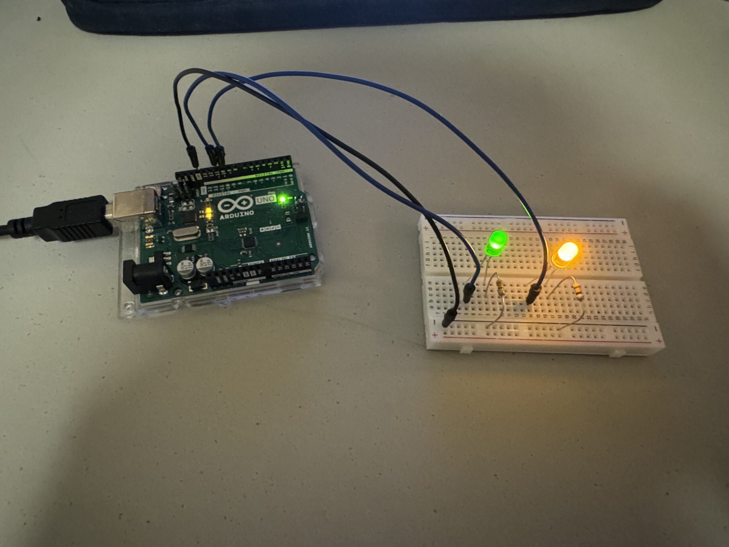
The main loop of the code continuously reads the analog values from the X and Y outputs of the joystick, as well as the digital states of the two buttons. It also listens for incoming serial data. When serial data is available and ends with a newline character, the code parses the data into an integer (`serialValue`). If `serialValue` is 1, it turns on the green LED and turns off the red LED; otherwise, it does the opposite. The joystick position (X and Y values) and button states are then sent to the serial port in a comma-separated format for external processing or monitoring. Finally, a small delay of 200 milliseconds is included before the loop repeats, allowing for consistent and controlled operation of the system.
Arduino Code Snippet:
void loop() {
  int posX = analogRead(X_pin);
  int posY = analogRead(Y_pin);

  button1State = digitalRead(button1Pin);
  button2State = digitalRead(button2Pin);

  if (Serial.available()) {
    int serialValue = Serial.parseInt();//incoming detection value
    if (Serial.read() == '\n'){
      if (serialValue == 1) {
        digitalWrite(gledPin, HIGH); // Turn LED on
        digitalWrite(rledPin, LOW);
    } else {
        digitalWrite(gledPin, LOW);  // Otherwise, turn LED off
        digitalWrite(rledPin, HIGH);
      }
    }
  }
  //sending data to p5js
  Serial.print(posX);
  Serial.print(",");

  Serial.print(posY);
  Serial.print(",");

  Serial.print(button1State);
  Serial.print(",");

  Serial.println(button2State);

  delay(200); // create a small delay before repeat loop
}
Part That I Am Proud Of:
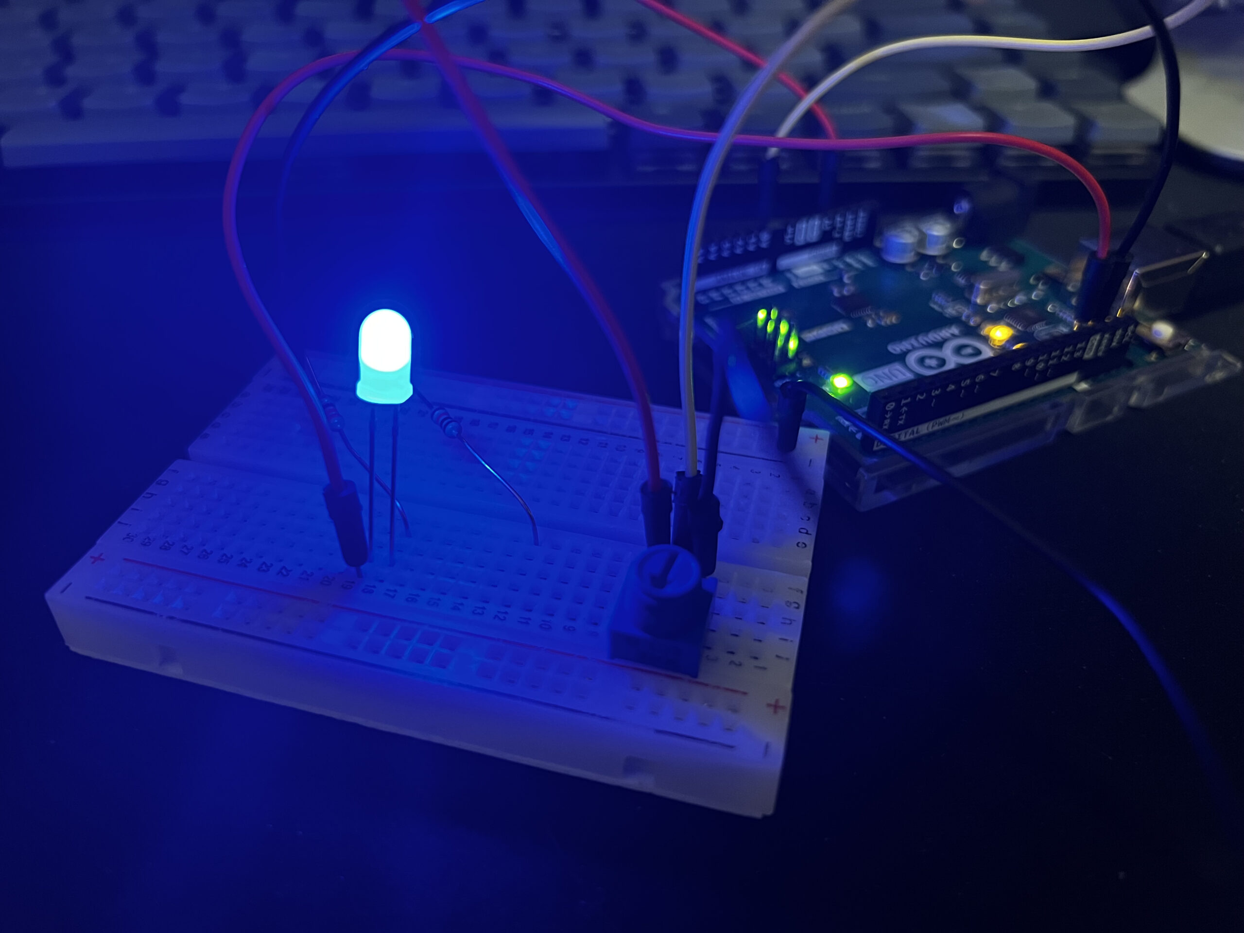
Within this project, I am proud of the different sprite interactions that I was able to utilize. Whether it is founding the treasure or being in contact with the sprite, they were all very interesting to think and code. Furthermore, I am also proud of the hardware construction of the project, especially implementing joystick and building the outer box, the hard part was putting and sticking the board inside the ox, but luckily I had relatively bigger box.
Resources used:
https://support.arduino.cc/hc/en-us/articles/4408887452434-Flash-USB-to-serial-firmware-in-DFU-mode
https://www.arduino.cc/reference/en/libraries/
Challenges faced:
One of the biggest challenges I faced was rather mysterious one. My laptop was not recognizing the arduino board. I have tried different cords, laptops, microcontrollers but it was not working, but apparently the problem was the wire that was connected to the 5v in the microcontroller. It started working after I changed the wire. Another aspect of the project that was difficult for me was soldering the led buttons. Somehow the melted alloy kept falling of after some time, which made me quite frustrated. Due to this, I spent relatively longer time soldering the wires and making sure that they are well connected.
Future Improvement:
There are definitely some improvements needed, whether it is in game mechanics or hardware aspect. For instance, there could be more variety of characters added to the game, so that users would have more variety. Since it is a level based game, there are always the opportunity to make more levels. Also, it could be better to use the collected treasures to procure something, whether it is a good boots to speed up or a better radar with wider range, making the game smoother and coherent. As for the hardware aspect, I would make more input possibilities like piezo speaker in order to let the user know if the radar detects a treasure or not. This could be much better choice than led lights. Furthermore, I would update the box so that it would look like and actual gaming console like xbox or playstation.
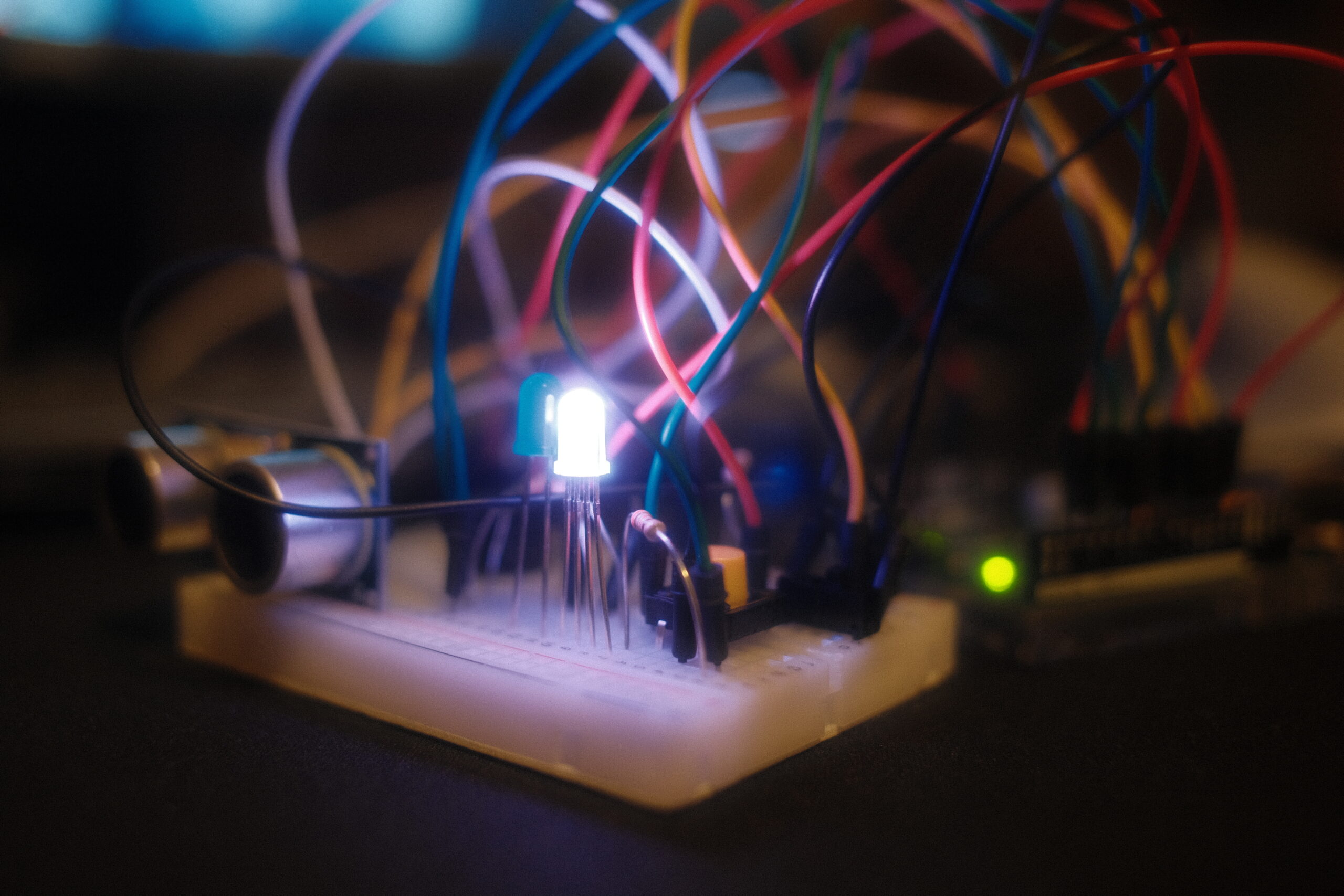
Project Images:
Project Videos:
User Testing:
Im Show Documentation:
The IM show went well. Several people played the game, but due to the small radar and large map, people took a bit long time to win the game, otherwise it went very smoothly. Because I keep the serial communication too long, there were times were it was not responding to the buttons, so I had to constantly refresh it, in case it did not work.

