Pen Plotter: Final Project Documentation

Concept

We (Samyam and Tim) designed a physical device that lets a user draw a sketch of their choice on p5.js and replicate it physically using a polar coordinate pen (plotter). In essence, the user can interact and control the device using a sketch as simple as an Archimedean spiral or as complex as a zine design of an engineering creation. It boils down to the user’s choice. Besides, the interconnectivity of the sketch, inspired by the Eulerian trial, adds to the artistic element of the system.

Drawing Platform

The project was primarily divided into four sections:

  1. Hardware and System Design
  2. p5.js Development
  3. Arduino Development
  4. Implementation and interaction between components

Hardware/ Device Design

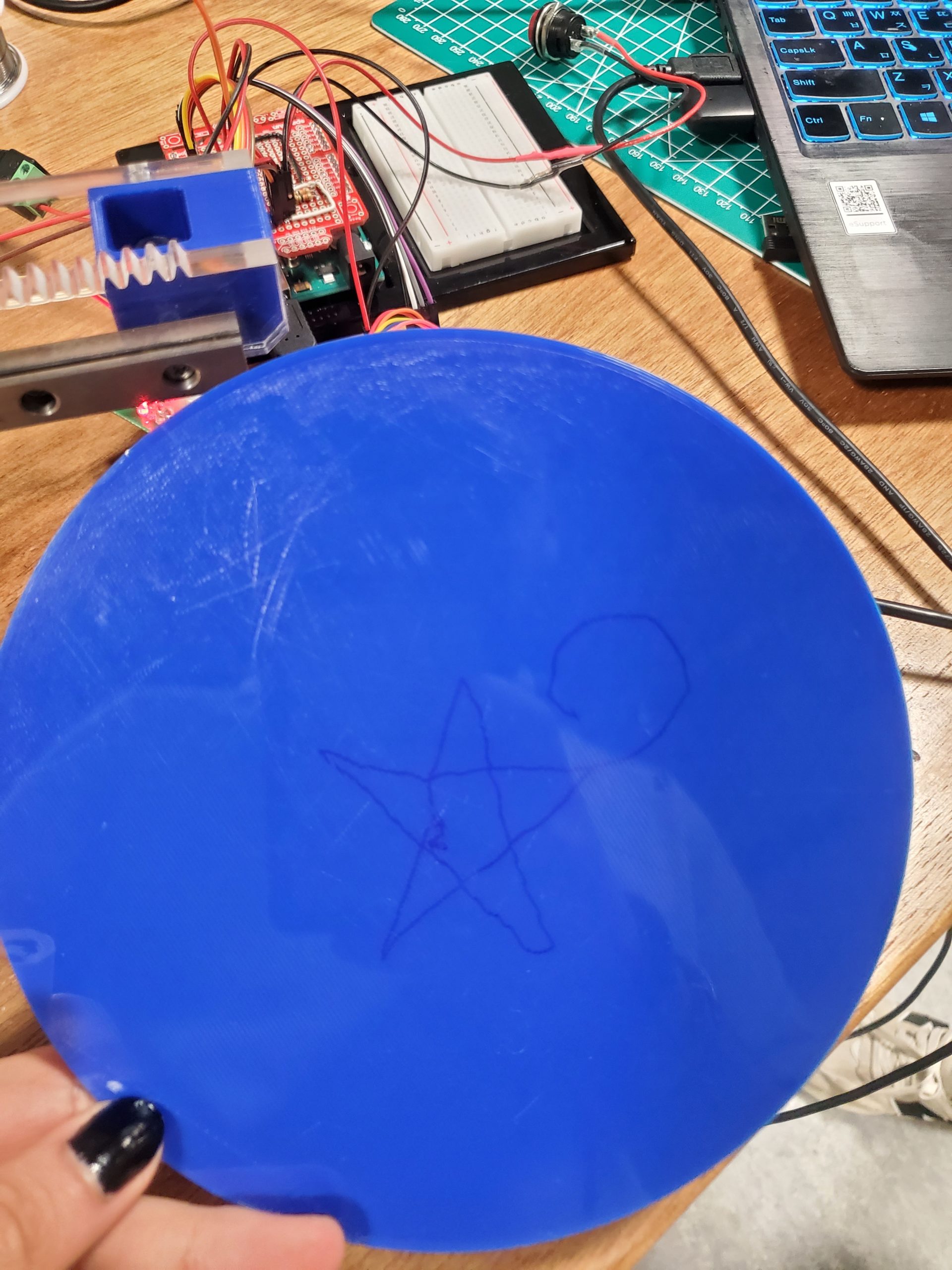
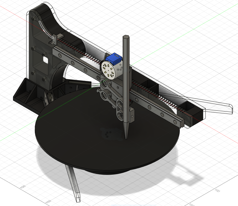
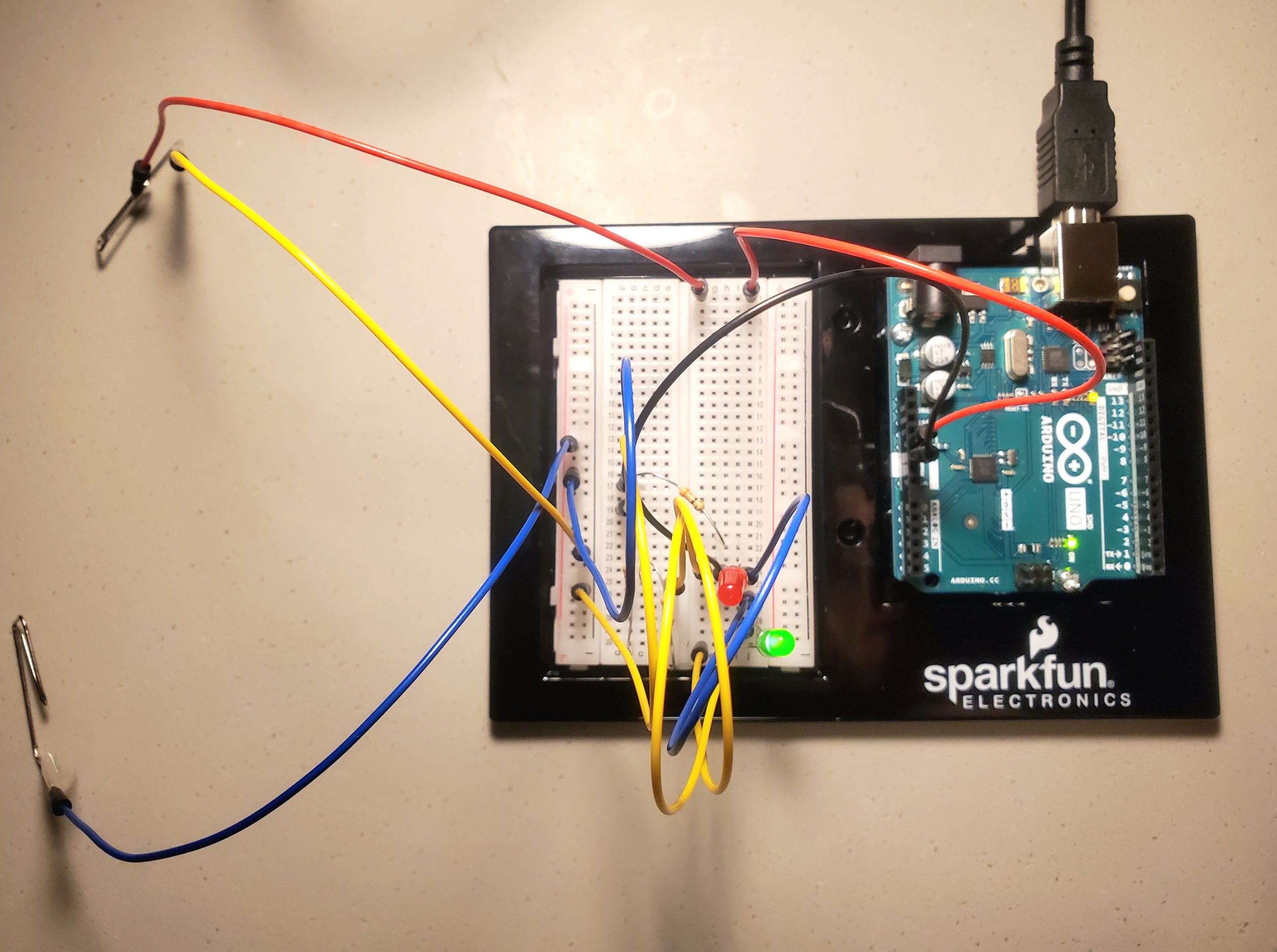
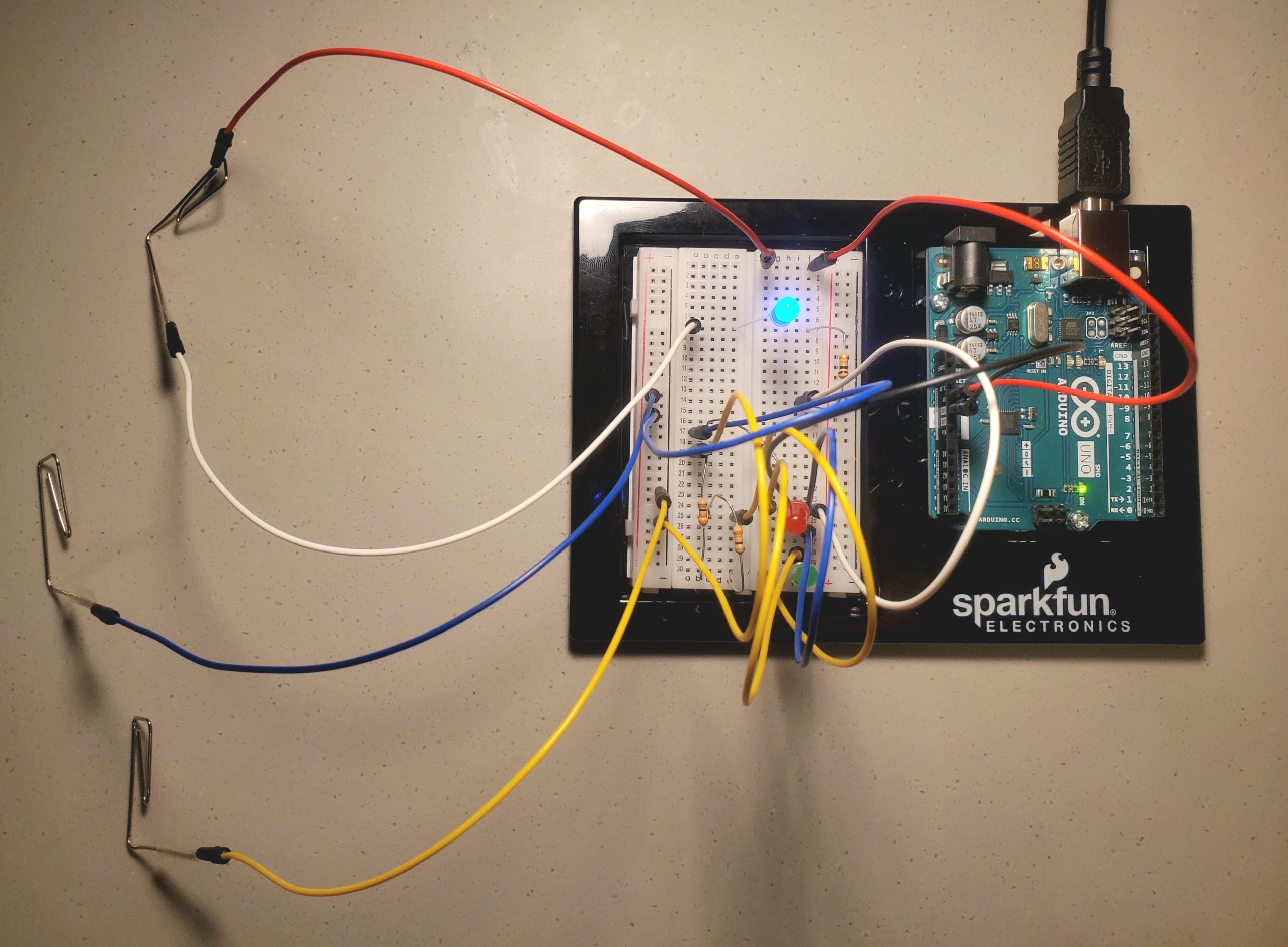
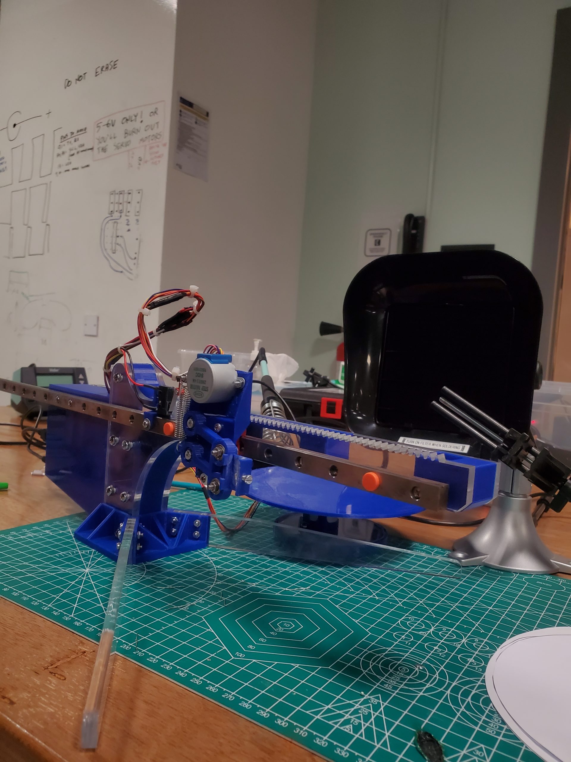
The system comprises of a bunch of mechanical components and electrical motors that complement the functionality of the device. The device is based on a 2-DOF system in which the plotter moves to and fro on a linear rail, while the bottom plate follows the rotational motion orthogonal to the linear rail. The movement of the base plate facilitates a variety of designs, thus allowing the user to sketch any form of drawing.

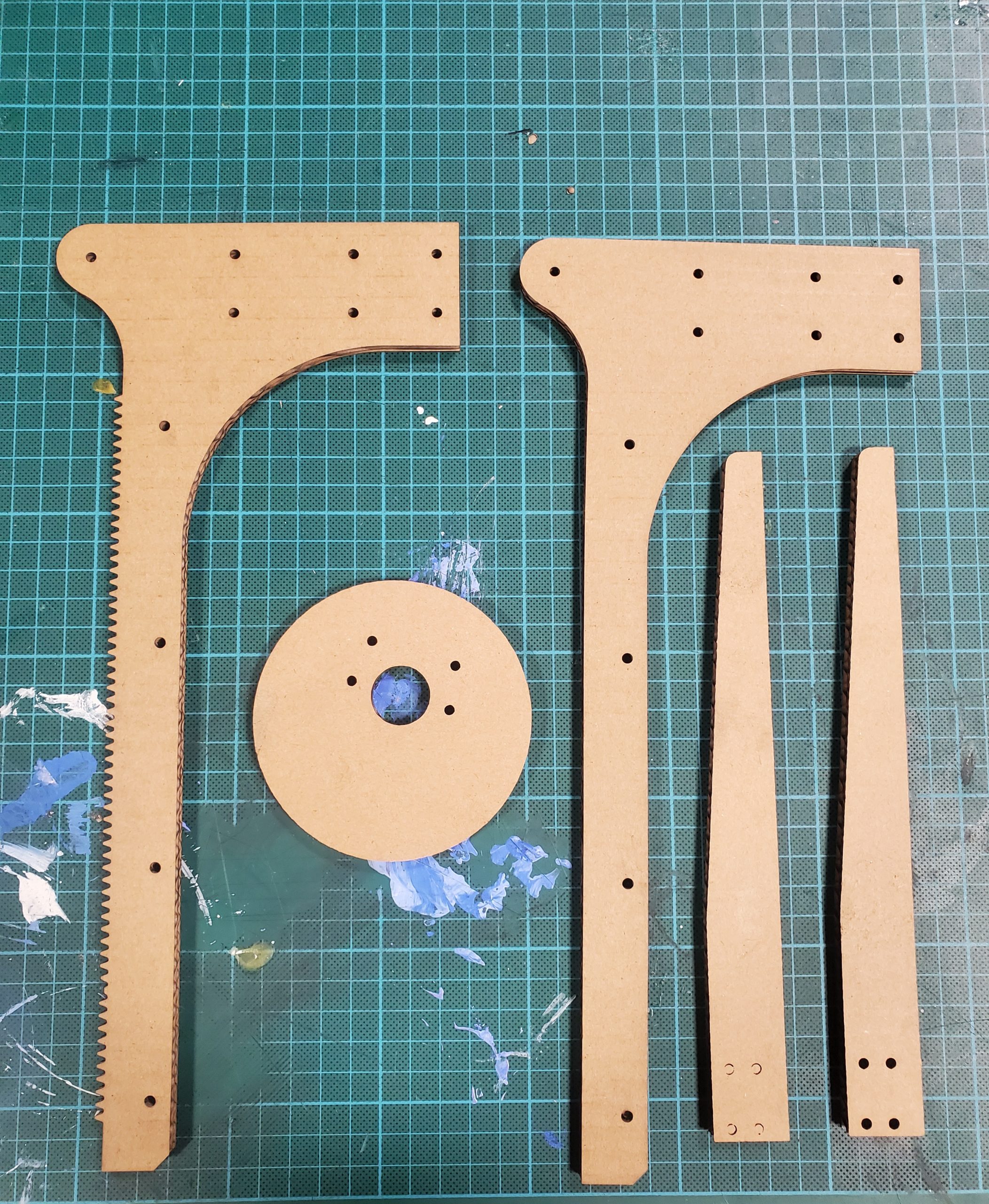
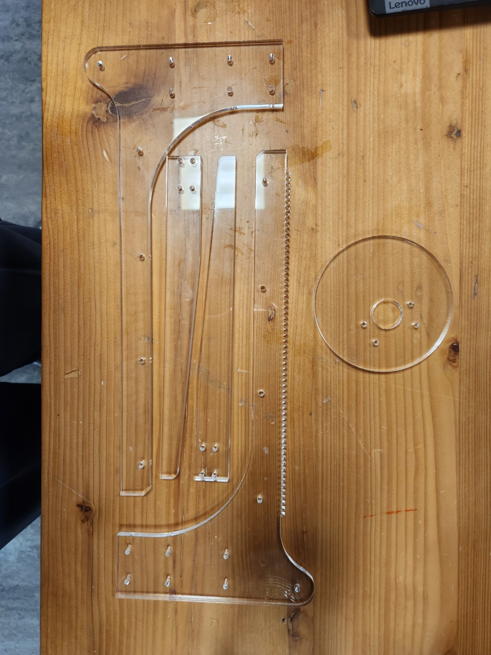
First, the 3D model of the device was completed using Autodesk Fusion 360 – afterward, the components were either laser cut or 3D printed. We laser cut the rack and pinion as well as the legs of the device, while the spacer between the laser-cut components, rotating base plate and the plotter holding components were 3D printed. In addition, we have purchased a linear guide rail, step motors and stepper-motor-driver board for precision drawing. Then, all of the components, including servo motors, were assembled to complete the physical design.

The motors and the driver boards are connected to the Arduino board, which is connected to p5.js to allow the transmission of user input into the physical system.

p5.js Coding

All the p5.js coding files are divided into two main JavaScript files:

  1. sketch.js: Contains the majority of the algorithm
  2. keyboard_keys.js: Contains the functions to track cursor movement

In addition, there is one “p5.web-serial.js” file that contains web serial functions adapted from the public web-serial library (Link).

The majority of the device’s software design depends on the p5.js component — from storing user input to transmitting data to the Arduino in the most efficient format.

At first, the user sketches a drawing using a mouse, a trackpad or a smart stylus. The interconnectivity of the design allows the user to connect all the components of the sketch. A simple if-conditional ensures that the sketch is being drawn, thus storing cartesian coordinates of the sketch only when the different points are registered; in return, this improves the efficiency of the system together as well as restricts the possibility of redundancy and system overloading. This functionality is further dependent on manually created functions like “mousePressed()” and “mouseReleased()” that alter a boolean “isClicked” based on the status of the drawing.

Here, we have moved the origin to the center of the canvas to replicate real-life situations. All the cartesian coordinates are then stored in an array titled “Positions[]” in a vector format. Since the physical platform is based on polar coordinates, all the coordinates need to be converted to the said format. Thus, a separate function named “cartToPolar()” is written that takes cartesian x and y coordinates as arguments and returns a list containing two equivalent attributes – radius and the angle of inclination.

function cartToPolar(x, y) {
  let radius, angle;
  let old_angle;
  let curr_angle;

  radius = sqrt(sq(x) + sq(y));

  angle = atan(abs(y) / abs(x));

  if (x >= 0 && y >= 0) {
    angle = angle;
    firstQuad = true;

    if (fourthQuad) {
      fullRotationNum++;
      fourthQuad = false;
    }

  } else if (x <= 0 && y >= 0) {
    angle = 180 - angle;
  } else if (x <= 0 && y <= 0) {
    angle = 180 + angle;
  } else if (x >= 0 && y <= 0) {
    angle = 360 - angle;
    fourthQuad = true;

    if (firstQuad) {
      fullRotationNum--;
      firstQuad = false;
    }
  }
  
  angle += fullRotationNum * 360;
  
  if(firstAngle){
    firstAngle = false;
    tempAngle = angle;
  }else{
    if(tempAngle - angle > 180){
      fullRotationNum++;
      angle += 360;
    }if(tempAngle - angle < -180){
      fullRotationNum--;
      angle -= 360;
    }
    tempAngle = angle;
  }

  let temp_list = [];
  temp_list[0] = map(radius, 0, sqrt(2 * sq(width / 2)), 0, disc_radius); // Mapped radius
  temp_list[1] = angle;

  return temp_list;
}


Here, we can see that the function receives x and y coordinates as arguments. Immediately after that, the radius is computed using a simple mathematical formula (d = (x^2 + y^2)^(0.5)), while the absolute value of the radius is determined using trigonometric relations. In order to compute the exact value of the angle, the quadrant of the coordinates is determined using a couple of if-statements and the absolute value computed above is modified. The process of altering the angle’s value is special in the first and the fourth quadrant. In the case of the first quadrant, a boolean ‘firstQuad’ is set to true and a variable ‘fullRotationNum’ is incremented that controls the rotation of the step motor fixed on the bottom plate. Similarly, in the case of the fourth quadrant, the boolean ‘fourthQuad’ is set to true and the variable ‘fullRotationNum’ is decremented. Since the rotation on a plane is calculated on a scale of 2 PI (360 degrees), this variable maintains the rotation angle without altering the motion of the step motor. Afterward, the true angle is increased based on the value of this variable.

Then the second set of if-conditionals is implemented to solve a bug in the system. Initially, without these statements, the bottom stepper motor would retract occasionally during a massive jump in the angular value, so these conditions manually compare the value of the angle with the old value stored in ‘tempAngle’ and if the jump is of a particular value, certain states of the if-conditions are executed, i.e., increasing and decreasing the value of ‘fullRotationNum’ and ‘angle’ respectively.

Finally, the radius is mapped to a scale of the maximum radius of the physical disc and the list containing two values – “mapped radius” and “modified angle” is returned to the callee function. Then, the data are transmitted to the Arduino after the user clicks the ‘SEND DATA’ button.

function button(text_, x, y, w, h) {
  // Checks if the cursor is within the button or not
  let isWithinButton =
    mouseX < x + w && mouseX > x && mouseY < y + h && mouseY > y;

  // Hover Effect
  if (isWithinButton) {
    fill(143, 148, 123);
    cursor(HAND);
  } else {
    fill("grey");
    cursor(ARROW);
  }

  // Button Setting
  stroke("black");
  strokeWeight(2);
  rect(x, y, w, h, 5);

  // Text inside the button
  textFont("Helvetica");
  stroke(5);
  textSize(25);
  fill("white");
  text(text_, x + 18, y + 32);

  // Return a boolean value
  return isWithinButton;
}

The algorithm behind the ‘SEND DATA’ button is coded manually in a function titled ‘send_data_button’. This function relies on a mother function ‘button’ that takes (1) the name of the button, (2) (3) x and y coordinates of the button and (4) (5) the height and width of the button. In order to create a hover effect, the size and color of the button are altered using if-conditions. Then, the function compares the location of the cursor with the location of the button and returns a boolean value indicating whether the cursor is inside or outside the button (true indicates inside and false indicates outside). Thus, when ‘send_data_button’ is coded, it first creates the button and then begins the data transmission process.

let first_point = false;

// Function that sends data to arduino
function send_data_button() {
  let x = canvas_w - 210;
  let y = canvas_h - 70;
  let w = 180;
  let h = 50;

  // If the cursor is within the button button() function returns 1, else 0;
  let sendBool = button("SEND DATA", x, y, w, h);

  // Sending the data if the cursor iswithin the button and mouse is clicked
  if (sendBool && mouseIsPressed && !first_point) {
    serial.write(String("H"));
    first_point = true;
    startSending = true;
    
    button_bool = true;
    print("Homing Machine...");
    
  
  }
  else
    button_bool = false;
}

The entire process of sending data to the Arduino depends on two boolean variables – “startSending” and “drawingFinished”. At the beginning of the transmission, a single character ‘H’ is transmitted to the Arduino in the form of a string. It indicates that the first coordinate is ready to be sent thus setting the variable ‘firstPoint’ to true inside the ‘send_data_button’ and displaying a message on the console that says ‘Homing Machine’, which essentially determines the position of the absolute origin or reference point of the plotter (it is completed every time a sketch has to be drawn). Then, the program continues inside the native draw() function.

let tmp = 1;
function draw() 
{
  background(203,203,205);
  myCirc();
  instruction_txt();
  
  //Buttons
  send_data_button();
  reset_button();

  // Translate the origin point to the center of the screen
  translate(width/2, height/2);
  
  
  // Restricting the sketch within the canvas
  let d_comp = pow((sq(mouseX - (width/2)) + sq(mouseY - (width/2))), 0.5);
  if (isClicked && (d_comp >= (sketch_radius/2)))
  {
    // If the cursor is outside of the circle and the button, execute this condition
    if (!button_bool)
    {
      isClicked = false;
      print("Draw within the canvas!");
    }
    
    // If the cursor is outside of the circle but within the button, exectute this condition
    else
    {
      isClicked = false;
      print("Button clicked!");
    }
    
  }
    

  // Make sure the mouse is clicked and cursor position is different
  if (isClicked && mouseX !== pmouseX && mouseX !== pmouseY) 
  {
    
    // Create a vector and add it to the list
    // let pt = createVector(mouseX, mouseY);          // When origin is at the top-left corner
    let pt = createVector(mouseX - width / 2, mouseY - height / 2);
    positions.push(pt);

    // Handle the case when x = 0
    if (pt.x == 0) pt.x = 0.01;

    // Mapping Cartesian to Polar and appending it in mappedPositions array
    let temp_list = [];
    temp_list = cartToPolar(pt.x, pt.y);
    let pt_mapped = createVector(temp_list[0] * one_px_mm, temp_list[1]);
    mappedPositions.push(pt_mapped);
    
    
    print("\nCounter: " + tmp);
    // Printing co-ordinates stored in the list(s)
    print("Cartesian: x: " + pt.x + " and y: " + pt.y);
    print("Polar:     r: " + pt_mapped.x + " and Angle: " + pt_mapped.y);
    tmp++;
  }

  // Draw Settings
  noFill();
  strokeWeight(5);
  strokeJoin(ROUND);

  // Go through the list of vectors and plot them
  beginShape();
  for (let i = 0; i < positions.length; i++) {
    let pt = positions[i];
    curveVertex(pt.x, pt.y);
  }
  endShape();


  // Data Transmission 
  if (startSending)
  // if (startSending) {
    if (inData == "0") 
    {
      let temp_var =
        str(mappedPositions[i].x) + "," + str(mappedPositions[i].y);
      let percent = int((i / mappedPositions.length) * 100);
      print("[" + percent + "% completed] " + temp_var);          // Progress on Console

      serial.write(String(temp_var));

      i += 1;
      
      
      // Check if all the points are trasmitted
      if (i == mappedPositions.length) {
        startSending = false;
        drawingFinished = true;
      }

      inData = "1";        // Reset the watch-dog variable
      
      
      if (i >= 1)
        first_point = false;
    }
  }
  
  // Change the settings after completing the drawing
  if (drawingFinished) {
    serial.write(String("E"));
    print("completed!");
    i = 0;

    startSending = false;
    drawingFinished = false;

    firstQuad = false;
    fourthQuad = false;
    fullRotationNum = 0;
  }


Just after plotting the points of the sketch on the p5.js canvas by looping through the cartesian list, the program checks the status of the ‘startSending’ boolean – if it is set to true and the value of value received from Arduino is ‘0’, it concatenates the radius and the angle of the point separated by a comma. This concatenated string, stored in a variable called ‘temp_var’, is sent to the Arduino (in the form of a string). This process of transmitting the entire message in the form of a string is done by calling the “String()” function of p5.js. Without this explicit call of the function, the message transmission is interrupted, thus the solution. Afterward, the status of the ‘firstPoint’ is set to false after the first coordinate has been sent. Similarly, one if-condition checks if all coordinates have been sent – when it evaluates to true, “drawingFinished” is set to true whereas “startSending” is set to false.

In addition to the functions/ methodologies described above, the program consists of a variety of serial communication functions like portConnect() and portDisconnnect() to track the physical connection between p5.js and the Arduino. At first makePortbutton() is called to create a button on the canvas that allows the user to select the wired connection. One important function is ‘serialEvent()’ function that tracks the data received from the Arduino and stores it in ‘inData’ variable. All these functions are mainly called in the setup() function and display corresponding messages on the console. Essentially, these functions facilitate the error-handling functionality of the system, thus avoiding unintended interruptions of the process.

Arduino Coding

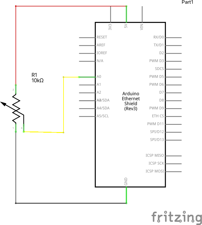
The Arduino board is coded to control the motion of two major components in the physical system: (1) a servo motor (connected to the vertically mobile plotter) and (2) two stepper motors (connected to the linear rail and the bottom plate).

At the very beginning of the program, two libraries (AccelStepper.h and Servo.h) are loaded in the project — we will use the methods of these libraries throughout the sketching process. The system uses two stepper motors as described earlier so global variables are fixed at the beginning of the code for individual motors. Afterward, basic settings for the step motors are set up — for example, determining the MotorInterfaceType (that allows four wire connections in a half-step mode) for the step motor, creating two individual instances of stepper motor classes from the imported library (armStepper and plateStepper respectively) and creating an object of the servo class called ‘penServo’. The AccelStepper library allows us to connect multiple stepper motors with controlled acceleration and deceleration. Similarly, different global variables are instantiated that are required throughout the sketching process.

Inside the setup() function, pinModes for input and output are set up. Similarly, the maxspeed and maxAcceleration of both the stepper motors are set to 1000 steps per cycle and 200 steps per second squared respectively. Also, the name (number) of the pin attached to the servo and the control of its shaft is controlled via attach() and write() methods of the servo library.

void homeMachine(byte _servoAngle) {
  penServo.write(90);
  armStepper.setSpeed(-400);
  armStepper.runSpeed();
  if (digitalRead(limitSw) == 1) {
    armStepper.setCurrentPosition(0);
    armStepper.moveTo(0);
    armStepper.runToPosition();
    centerPen(_servoAngle);
    Serial.write(0);
  }
}


Inside the draw() function, the program homes the machine using a manual function titled ‘homeMachine()’ that takes ‘servo angle’ as an argument. This function sets the angle of the servo to 90 and the speed of the steppers to -400. Then it checks if the value stored in ‘limitSw’ ( variable that stores input value) is ‘1’ (when the switch is pressed), the stepper attached to the plotter (arm) moves to the origin point and a reference point is established by calling a function called ‘centerPen()’ that takes servo angle as input.

void centerPen(byte _servoAngle) {
  armStepper.moveTo((int)(25 / halfStepToMm));
  armStepper.runToPosition();
  armStepper.setCurrentPosition(0);
  armStepper.setMaxSpeed(1000);
  penServo.write(_servoAngle);

  homing = false;
}


In the linear rail, 0.02047 mm equals 1 step, thus using this value, the function ‘centerPen()’ moves the pen to the location of the reference point, while the value received from the argument controls the angular movement of the motor. After this function, the ‘homing’ variable is set to false marking the end of the first step.

if (Serial.available() > 0) {
    input = Serial.readString();

    if (input == "H") {
      homing = true;
      firstPoint = true;
      machineStart = true;
    } else if (input == "E") {
      homing = true;
      machineStart = false;
      firstPoint = true;
      drawing = false;ic
    }
  }

  if (machineStart && input.length() > 3) {
    coordVal[0] = input.substring(0, input.indexOf(",")).toFloat(); // r
    coordVal[1] = input.substring(input.indexOf(",") + 1, input.length()).toFloat();  //theta

    if (firstPoint) {
      penServo.write(90);
      armStepper.setCurrentPosition(0);
      plateStepper.setCurrentPosition(0);
      firstPoint = false;
      angleTemp = coordVal[1];
    } else if (drawing) {
      penServo.write(110);
    }

    if (abs(angleTemp - coordVal[1]) > 90) {
      drawing = false;
      d.write(95);
    }

    armStepper.setMaxSpeed(1000);
    plateStepper.setMaxSpeed(1000);

    armStepper.moveTo((int) (coordVal[0] / halfStepToMm));
    armStepper.run();
    plateStepper.moveTo(-1 * (int) (coordVal[1] / halfStepToDegrees));
    plateStepper.run();

    if (armStepper.distanceToGo() == 0 && plateStepper.distanceToGo() == 0) {
      angleTemp = coordVal[1];
      Serial.write(0);
      drawing = true;
      input = "";
    }
  }

The program then checks the data received from p5.js. If the value is “H”, homing, machineStart and firstpoint variables are set to true thus homing the machine before every sketch. Similarly, if the value is “E”, corresponding attributes are altered to facilitate different functionality of the device.

Based on the attributes set above and the data received from p5.js, the program proceeds. The message is sliced and ‘radius’ and ‘angle’ are stored in an array coordVal[].

If the firstPoint variable is set to true, the servo angle is set to 90 and both the stepper motors are moved to position 0 and the angular value is stored temporarily; in the case, it’s not the first point, the servo angle is set to 110. Then, the angular value stored in the temporary variable and in the arrays are compared, and the global variable ‘drawing’ is set to ‘false’ if the difference is greater than 90.

Afterward, the positions of the stepper motors are changed based on the values received from p5.js. Using the radius of the point, the plotter’s target position is set; also, the plate’s target position is set using the radius and halfStepToDegrees conversion. Then, if the distance(s) from the current position to the target position of both the stepper motors are 0 respectively, the drawing variable is set to true and a string ‘0’ is sent to p5.js. This way, the device moves based on the input from p5.js and a sketch is replicated on the device.

Communication between Arduino and p5.js

For this project, Arduino and p5.js communicate with one another in two ways – in other words, it is a bidirectional communication. At first, when the user clicks the “SEND DATA” button on the p5.js canvas, p5.js sends a character “H” in the form of a string followed by a series of strings in the format <radius, angle> (here brackets do not hold any significance). Once the first coordinate is sent, Arduino verifies its authenticity, and if it is a valid one, the stepper motors and the servo motor take a new position(s). Upon successful completion of the movement, Arduino sends back “0” as a string to p5.js. This instructs p5.js to send a second coordinate and so forth. This way, two-way communication takes place before sending a new set of coordinates.

Proud Aspects

The project has been a demanding undertaking. From designing hardware components and waiting for hours to get parts printed to designing the software that dictates the functioning of the device has been an arduous task. Despite the number of bugs faced, we were able to find our way through, and here is our final project.

During this time, the phase that required a notable amount of time was ‘cartToPolar(x, y)’ function that we manually coded. As described earlier, it transforms ordinates of individual cartesian coordinates into polar form since the machine understands polar coordinates only. Thus, this function was a no-brainer for the device to function. We initially coded the function based on our assumptions. However, as moved to the user-testing phase, we faced a few bugs that would not hinder the performance per se but rather would reduce the charm of the project. Thus, after hours and even days of debugging, we were able to finalize the project ideas. Now, this function controls the motion of the device. It takes a set of extremely raw values and transforms them into a value that the drawing platform understands. Besides, the function handles the extreme conditions of the radii values; this way, we were able to avoid situations where the program may crash. It took a massive amount of our time as well as Mathematics oriented brainstorming.

Similarly, building the whole platform was a task in itself. We were assembling parts built from different processes — laser cutting and 3D printing — thus, when the device took a shape, it was an eternal feeling. We were able to precisely determine its structure beforehand and correctly build its physical structure. It is something that we are definitely happy about.
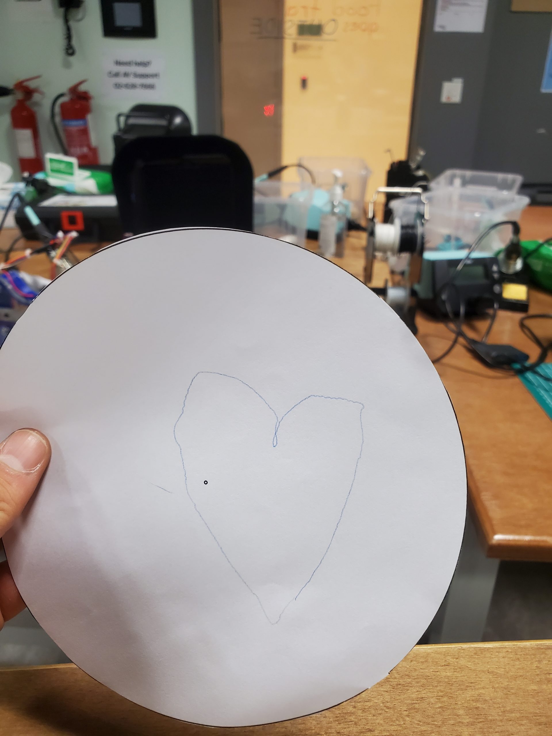
Interaction

In this project, the user is in charge of the drawing. There is a circle on the p5.js canvas; this is where the user can draw any sketch of their choice — here we are basically converting our square canvas to a circular one to replicate the base plate of the device. Once, the drawing is completed, the user can click ‘SEND DATA’ button and wait for the drawing to complete.

Future Improvements

In this project, we were able to reduce the time the device requires to draw a sketch by half. The device consists of numerous individual elements, thus after carefully redoing software algorithms, we were able to bring down the time complexity of the physical device. That said, the device still takes some time to complete the drawing. Thus, our future priority would be to reduce the time even more so that it functions at its peak speed. This could be done by recording every single point through which the cursor passes – at present, the speed of the cursor determines the number of points recorded, so this could be solved in future iterations to reduce the noise.

Similarly, the parts are 3D printed and the components we purchased belonged to a comparatively affordable category. Thus, in future iteration(s), we would build the physical components using more expensive and reliable components, thus avoiding the noise that these components catch at present. Even though the noise is negligible, at some point, the user may notice it. Thus, our priority would be to decrease the noise using high-quality components.

Individual Contribution

Task Person
Hardware Design & Assembly Tim
Arduino Tim
p5.js Samyam
Design Implementation Samyam
Hardware + Software Communication Both
User Testing Both
Blogs/ Documentation and Video Samyam
Bugs and Final Polishing Both
Hardware Casing Tim

Reflection

This project took a total of more than two weeks to complete — from designing its raw structure to actually building it and integrating it with the software component. Sometimes, we were stuck on a bug for days even though the idea would work theoretically, while other times, every testing would go as planned. Nevertheless, it was an interesting project and we are glad about the way the project turned out to be.

Yay! It’s working.

Watch the user testing here:

Final Sketch:

Final Sketch

Find the GitHub link to the project here.

Final Project – User Testing [Samyam & Tim]

Progress

Following our last blog post, we (Samyam and Tim) are almost done with the project. The project was divided into three different major components: 

    1. Building Hardware
    2. p5.js component
    3. Arduino component

After assembling the 3D printed and laser-cut pieces with motors, we have made some changes in the p5.js component – it has been adjusted so that the latency in data transfer does not affect the bidirectional communication between p5.js and the Arduino. In the same way, the Arduino code has been modified to facilitate smooth communication between those two components. Once the user clicks the SEND DATA button, p5.js sends data to the drawing arm via the Arduino, which in return sends a confirmation message to p5.js; this way, p5.js knows when to send the next message. In the meantime, the physical arm keeps on drawing the sketch. When all the data are sent from p5.js, the completed sketch can be found on the base plate of the platform. 

User Testing 

Here, after setting up the device, we draw a sketch of a star with a curved hook on one edge. Once the user clicks on SEND DATA button, mapped coordinates (mapped to polar coordinates) are relayed to the Arduino, and the sketch is drawn on the plate. The progress of the sketch can be tracked using the p5.js console, where the completion percentage as well as the coordinates transferred are displayed. 

Find the user-testing video here along with the final sketch drawn on the plate.  

The completed sketch:

Final Sketch

Future Plans

The device is functional and working as expected. Thus, we plan on further enhancing the hardware as well as software components of the project. The time the device takes to complete the sketch immensely depends on the complexity of the sketch, thus our plan is to improvise its performance as much as possible. In addition, the base plate will be re-engineered so that the user can place a paper for better visibility of the final sketch. 

Final Project – Progress

Concept/ Idea

For the project, we (Tim and Samyam) have decided to develop a system that lets the user sketch a diagram or shape on the p5.js canvas. This sketch then will be used to control the physical arm of our drawing platform. To accomplish this, we will send canvas data from p5.js to Arduino, controlling different parts of the drawing device. 

The striking feature of the project is the interconnectivity of the drawing. The user can draw as many shapes or sketches as they desire, but everything will remain connected to each other. This idea is inspired by the Eulerian trail, where the floor is divided into multiple sections when multiple people step on it. 


Hardware Design

Following the previous post, we have finalized our concept to be a polar coordinate pen plotter that plots a shape drawn on the computer screen. Unlike our previous design, we have decided to make a 2-DOF system (linear movement on one axis, and rotational motion around an orthogonal axis). Although the mechanical design of the machine became more complex, this will make the software much simpler. For the design, we used Autodesk Fusion 360 to create a 3d model, which was manufactured with a 3d printer and a laser cutter. For the precision of the plotter, we purchased a linear guide rail, commonly used in CNC machines and 3d printers; we used a stepper motor for controlled movement. Below is a 3 d model design for the project:

A rack and pinion system was used, so as a gear connected to a stepper motor rotates, it will move the whole pen carrier along a linear rail.

One distinctive feature of this plotter is that the position of the rotating (base) plate can be adjusted freely. This allows the user to produce different drawings every time he or she moves the base plate.

Because drawings on the screen use cartesian coordinates, we had to convert XY coordinates into polar coordinates. This was very simple because T:(X,Y) –> (r, θ), where r = sqrt(x^2+y^2) and θ = tan^-1(y/x). r will determine the movement of a linear DOF and θ will determine how much the base plate will rotate. Do you see how simple the calculation got compared to the previous design?

Making Parts

As mentioned above, a laser cutter and 3d printer was used to make parts.

Prototype

Laser Cutting

Due to the high rigidity of the acrylic plates, we decided to make the main body with acrylic parts. Based on our design, we were able to laser-cut the parts that we needed.

3D Printing

Parts that cannot be made with laser cutters were made using 3d printers. This included a base plate, a spacer between acrylic parts, and a pen moving mechanism.

P5.js Component

The preliminary phase of the project depends on the functionalities of the p5.js component. The user can use the mouse to draw shapes on the p5.js canvas; the shape will be replicated in the actual design using the Arduino component. 

In order to sketch a shape on the canvas, the user can click the mouse and drag the cursor to draw the desired shape. This is regulated by two functions titled “mousePressed()” and “mouseReleased()” respectively. When the mouse is clicked, the global variable “isclicked” is set to True and when the mouse click is released, “isClicked” is set to False. This way, the global variable keeps track of the sketch being drawn. 

Once the mouse is clicked, the program checks the position of the cursor – if it is static while being tracked, the position is ignored, i.e., the user must move the cursor, while the mouse is being clicked, so that a sketch can be drawn on the screen. It is facilitated by the following code:

// Make sure the mouse is clicked and cursor position is different
if (isClicked && mouseX !== pmouseX && mouseX !== pmouseY)
{
  // Create a vector and add it to the list
  // let pt = createVector(mouseX, mouseY);          // When origin is at the top-left corner
  let pt = createVector(mouseX - width/2, mouseY - height/2);
  positions.push(pt);
  // console.log(pt.x, pt.y);
  
  
  // Mapping Cartesian to Polar and appending it in mappedPositions array
  let temp_list = [];
  temp_list = cartToPolar(pt.x, pt.y)
  let pt_mapped = createVector((temp_list[0] * one_px_mm), temp_list[1]);
  mappedPositions.push(pt_mapped);
 
}

Here, we can see, if the aforementioned conditions are met, a new vector based on the cartesian location of the cursor is created and appended to the (global variable) list “positions”. The entire canvas is translated to the middle of the canvas, that’s why a certain amount is subtracted to the x and y coordinates before appending to the list. Similarly, with the help of a function titled “cartToPolar()”, each vector in the cartesian coordinates is converted to polar coordinates equivalent and appended to a list titled “mappedPositions[]”.

function cartToPolar(x, y)
{
  let radius, angle;
  
  radius = sqrt(sq(x) + sq(y));
  // console.log(radius);
  
  angle = atan(y/x);
  // console.log(angle);
  
  let temp_list = [];
  temp_list[0] = map(radius, 0, sqrt(2 * sq(width/2)), 0, disc_radius);         // Mapped radius
  temp_list[1] = angle;
  
  return temp_list;
  
}

The program also consists of two manually coded buttons — RESET and SEND DATA. The former reset the canvas and resets the required variables so that the sketch can be redrawn from the beginning. While the latter is used to send data to the Arduino connected to the system. Both these functions derive from a template function titled “button()” that takes text, x, y coordinates, height and width of the button as arguments. To develop the SEND DATA functionality, a function named “send_data_button()” calls the main button function with the required parameters. The main function returns a boolean value [1 if the cursor is within the button and 0 otherwise]. If the boolean value is 1 and the button is pressed, the values in the “mappedPositions[]” list are forwarded to the Arduino using an inbuilt serial.write() function. In each iteration, the angle of the coordinate is transmitted following its radius. 

function reset_button()
{
  let x = 26;
  let y = canvas_h - 70;
  let w = 125;
  let h = 50;
  
  // If the cursor is within the button button() function returns 1, else 0;
  let resetBool = button("RESET", x, y, w, h);
  
  // Resetting sketch if the cursor iswithin the button and mouse is clicked
  if (resetBool && mouseIsPressed)
  {
    positions = [];
    mappedPositions = [];
    isClicked = false;
  }
  
}


The p5.js component also comprises different functions like choosePort(), openPort(), serialEvent() and so forth to keep track of the port selection, data transmission as well as error handling. 

Arduino Component

Arduino is connected to 2 stepper motors, each controlled by different stepper drivers. The Arduino will read data sent from p5js and move the pen and plate accordingly. Total of 2 switches will be connected to the board, both for homing the pen carrier (one push button and one limit switch).

When the button is pressed, the Arduino will begin to move the pen carrier back until the carrier hits the limit switch. Once the limit switch is closed, the Arduino will move the pen carrier slightly front and move the carrier back until it hits the switch again. The second part will be done at a much slower speed for accuracy. Homing a pen carrier is significant because the machine must always be aware of the pen’s current position. Homing allows the machine to always start from the same initial position.

This is the sample code showing how the code will work (no motors added yet):

const int limitSw = 7;

const int homeButt = 8;

long long currentTime = 0;

bool homing = false;

bool reachEnd = false;

void setup() {

  // put your setup code here, to run once:

  pinMode(limitSw, INPUT);

  pinMode(homeButt, INPUT);

  Serial.begin(9600); 

}


void loop() {

  // put your main code here, to run repeatedly:

  if(!homing && digitalRead(homeButt) == 1){

    homing = true;

  }


  if(homing){

    if(!reachEnd){

      Serial.println("homing fast");

      if(digitalRead(limitSw) == 1){

        Serial.println("SW pressed");

        reachEnd = true;

        currentTime = millis();

      }

    }

    else{

      Serial.println("homing slow");

      if(digitalRead(limitSw) == 1 && millis() - currentTime > 500){

        Serial.println("SW slow pressed. homing complete");

        homing = false;

        reachEnd = false;

      }

    }

  }

}

The other part of the code will include moving each part accordingly to the coordinate values from p5js. This would be relatively easy to achieve because we can calculate how much each part will move in mm when the motor turns by half or a single step.

Further coding can be done once we are ready with fully assembled hardware.

Future Plan

The time it takes to 3D print parts is the only problem we are facing until now. Once we are done printing our parts, we will be able to assemble the parts together soon. 

For now, the future plan includes the functionality to successfully coordinate the Arduino component with the data sent from the p5.js component. Since the canvas sketch is drawn based on cartesian coordinates, while the physical drawing is based on polar coordinates, we are planning to program the project so that artistic output is achieved. 

Demo

The software phase of the project can be tested here using this link. The project will be completed once the printing phase is completed.

Final Project – Preliminary Idea

Concept

For the final project, I am still in the process of finalizing an option, but three of my initial ideas are the following: 

  1. Working on my midterm project
  2. Building a physical car that can be controlled using Arduino 
  3. A runner game where the character/ object needs to avoid obstacles 

Each of the ideas consists of two primary sections: p5.js and Arduino.

p5.js Component

For the first project, I will work to further improve the ‘chasing’ mechanism of the game. For the final project, once again, the system should be able to allow user to control the character using a keyboard/ mouse (initially). If I decide to go with this idea, I am planning on making infinite levels or lengths so that the user can interact with the game as long as they desire. 

Later, the idea of serial communication will be incorporated in order to allow a physical device to play the game. 

For the second project, I will have to work from scratch to develop a system that keeps track of user input from the keyboard or mouse, and then control the motion of the actual device. If I decide to build this device, I assume the p5.js task will be less compared to the physical computing work. Either way, I intend to build a car that interacts with the p5.js and lets the user control its motion. 


Arduino/ Physical Computing

For the first or the final project, the purpose of physical computing will be to facilitate the user to play the game without using their keyboard or mouse – in other words, it will use electrical components and sensors to record user input either in the form of digital or analog data. This data will alter some attributes of the game components as a result the game can be played using an Arduino component. 

The second option heavily relies on physical computing. The first job is to build a functional car. Then, it should be able to communicate with p5.js for control. Additionally, there could be a second physical device that could control the car instead of using the keyboard. 

The sensors and components that I may use are potentiometers, ultrasonic sound sensors, LEDs, photosensitive resistors (LDRs) as well as servo motors, wheels and DC batteries (for the second option). 

I will go with one idea, but I am concerned about the availability of additional sensors the second option may require. The coding part should not consume a lot of time, but the physical computing part may take a while. Either way, I look forward to developing a system that communicates with p5.js and Arduino to control an object or a character in the game environment. 

Week 11: Serial Communication Exercises

Exercise 1

Make something that uses only one sensor on Arduino and makes the ellipse in p5 move on the horizontal axis, in the middle of the screen, and nothing on Arduino is controlled by p5.js.

For this exercise, a tiny circle’s x-coordinates are controlled by the reading from a potentiometer. The Arduino sends data to p5.js and the data received is used to control the movement of the circle on the canvas. 

The schematics of the circuit are as below. 

Two separate files behind this exercise are:

p5.js Code:

// Global variables added
let h = 1000;          // Canvas height
let w = 1000;          // Canvas width
let ellipse_height = 50;
let ellipse_width = 50;


// variable to hold an instance of the p5.webserial library:
const serial = new p5.WebSerial();
 
// HTML button object:
let portButton;
let inData;                   // for incoming serial data
let outByte = 0;              // for outgoing data
 

function setup() 
{
  createCanvas(w, h);          // make the canvas
  
  // check to see if serial is available:
  if (!navigator.serial) {
    alert("WebSerial is not supported in this browser. Try Chrome or MS Edge.");
  }
  // if serial is available, add connect/disconnect listeners:
  navigator.serial.addEventListener("connect", portConnect);
  navigator.serial.addEventListener("disconnect", portDisconnect);
  // check for any ports that are available:
  serial.getPorts();
  // if there's no port chosen, choose one:
  serial.on("noport", makePortButton);
  // open whatever port is available:
  serial.on("portavailable", openPort);
  // handle serial errors:
  serial.on("requesterror", portError);
  // handle any incoming serial data:
  serial.on("data", serialEvent);
  serial.on("close", makePortButton);
}


function draw() 
{

  background(50);
  fill(255);

  textSize(25);
  text("Raw sensor value: " + inData, 30, 50);
  
  
  // ------------------ Ellipse Values ----------------
  let max_pot_reading = 255;
  let map_error_corr = ellipse_width/2;
  
  // X-coordinate is scaled based on the readings from potentiometer
  let scaled_x_pos = map(inData, 0, max_pot_reading, map_error_corr, (w-map_error_corr));
  
  
  // Draw ellipse using the values determined above
  draw_ellipse(scaled_x_pos, (h/2 - map_error_corr), ellipse_height, ellipse_width);
  
  
  // Text Display on the right side of the canvas
  let rounded_x_pos = round(scaled_x_pos, 2);          // Data rounded upto 2 decimal places
  textSize(25);
  fill("white");
  text("Scaled X-position: " + rounded_x_pos, (w/2 + 150), 50);
  
}


// Function to draw an ellipse
// Aruguments; (x, y) coordinates && width and height
function draw_ellipse(x, y, w_, h_)
{
  fill("red");
  ellipse(x, y, w_, h_);
}


// if there's no port selected, 
// make a port select button appear:
function makePortButton() {
  // create and position a port chooser button:
  portButton = createButton("choose port");
  portButton.position(10, 10);
  // give the port button a mousepressed handler:
  portButton.mousePressed(choosePort);
}
 
// make the port selector window appear:
function choosePort() {
  if (portButton) portButton.show();
  serial.requestPort();
}
 
// open the selected port, and make the port 
// button invisible:
function openPort() {
  // wait for the serial.open promise to return,
  // then call the initiateSerial function
  serial.open().then(initiateSerial);
 
  // once the port opens, let the user know:
  function initiateSerial() {
    console.log("port open");
  }
  // hide the port button once a port is chosen:
  if (portButton) portButton.hide();
}
 
// pop up an alert if there's a port error:
function portError(err) {
  alert("Serial port error: " + err);
}
// read any incoming data as a string
// (assumes a newline at the end of it):
function serialEvent() {
  inData = Number(serial.read());
  console.log(inData);
}
 
// try to connect if a new serial port 
// gets added (i.e. plugged in via USB):
function portConnect() {
  console.log("port connected");
  serial.getPorts();
}
 
// if a port is disconnected:
function portDisconnect() {
  serial.close();
  console.log("port disconnected");
}
 
function closePort() {
  serial.close();
}


Arduino Code:

int potPin = A0;

void setup() 
{
  Serial.begin(9600); // initialize serial communications
}
 
void loop() 
{
  // read the input pin:
  int pot_read = analogRead(potPin); 

  // remap the pot value to fit in 1 byte:
  int mappedPot = map(pot_read, 0, 1023, 0, 255); 

  // print it out the serial port:
  Serial.write(mappedPot);    
                           
  // slight delay to stabilize the ADC:
  delay(1);                                          
  
  // Delay to send 10 times per second 
  delay(100);
}

Use this link to access the p5.js editor.


Exercise 2

Make something that controls the LED brightness from p5.js.

In this exercise, keyboard arrows can be used to control the movement of a ball on the screen — X-coordinates of the ball. As the ball is moved across the screen, its gradient changes (darker red means less bright LED, whereas brighter/ true red means brighter LED). In this exercise, when the ball is at the leftmost part of the canvas, the LED attached emits less light and vice versa. 

Here, the ball is located in the middle of the screen and is moderately red. As it is moved to different sides using the arrows, its color changes accordingly — in return, the LED’s brightness changes as well.

The schematics of the circuit are as below. 

Two separate files behind this exercise are:

p5.js Code:

// Global variables added
let h = 1000;          // Canvas height
let w = 1000;          // Canvas width
let ellipse_h = 50;
let ellipse_w = 50;
let ellipse_x = w/2;
let ellipse_y = h/2;
let ellipse_vx = 0;
let error_corr = (ellipse_w/2);
let ellipse_vel = 3;


// variable to hold an instance of the p5.webserial library:
const serial = new p5.WebSerial();
 
// HTML button object:
let portButton;
let inData;                   // for incoming serial data
let outByte = 0;              // for outgoing data


function setup() 
{
  
  createCanvas(w, h);          // make the canvas


  // check to see if serial is available:
  if (!navigator.serial) 
  {
    alert("WebSerial is not supported in this browser. Try Chrome or MS Edge.");
  }
  
  // if serial is available, add connect/disconnect listeners:
  navigator.serial.addEventListener("connect", portConnect);
  navigator.serial.addEventListener("disconnect", portDisconnect);
  
  // check for any ports that are available:
  serial.getPorts();
  
  // if there's no port chosen, choose one:
  serial.on("noport", makePortButton);
  
  // open whatever port is available:
  serial.on("portavailable", openPort);
  
  // handle serial errors:
  serial.on("requesterror", portError);
  
  // handle any incoming serial data:
  serial.on("data", serialEvent);
  serial.on("close", makePortButton);


}
 
function draw() {

  background(50);
  displayText();

  let color_gradient = map(ellipse_x, 0, (w - error_corr), 0, 255);
  let color_ = color(color_gradient, 0, 0);
  draw_ellipse(ellipse_x, ellipse_y, ellipse_w, ellipse_h, color_);
  pos_check();
  pos_update();
  
}


function displayText()
{
  textSize(25);
  fill("white");
  text("Move the ellipse using the RIGHT and LEFT arrows of the keyboard: ", error_corr * 5, h/2 - 400);
}


// Function to draw an ellipse
// Aruguments; (x, y) coordinates && width and height
function draw_ellipse(x, y, w_, h_, color)
{
  fill(color);
  ellipse(x, y, w_, h_);
}


function pos_check()
{
  if ((ellipse_x - error_corr) <= 0)
    ellipse_x = error_corr;
  else if (ellipse_x >= (w - error_corr))
    ellipse_x = w - error_corr;
}

function pos_update()
{
    ellipse_x += ellipse_vx;
}


function keyPressed() 
{
  // If RIGHT_ARROW is pressed, the character needs to move right, so set horizontal velocity using global var
  if (keyCode === RIGHT_ARROW)                   
  {
    ellipse_vx = ellipse_vel;
    
  }
  
  // If LEFT_ARROW is pressed, the character needs to move left, so set horizontal velocity using global var
  if (keyCode === LEFT_ARROW) 
  {
    ellipse_vx = -ellipse_vel;
  }
  
  let serial_val_ = (map(ellipse_x, 0, (w - error_corr), 0, 255));
  serial.write(serial_val_);
  // print("Serial " + serial_val_);


}


// Function that helps to move the ellipse one step at a time
function keyReleased() 
{
  // After RIGHT or LEFT arrow is released, set horizontal velocity to 0
  if (keyCode === RIGHT_ARROW || keyCode === LEFT_ARROW) 
  {
    ellipse_vx = 0;
  }

}


// if there's no port selected, 
// make a port select button appear:
function makePortButton() {
  // create and position a port chooser button:
  portButton = createButton("choose port");
  portButton.position(10, 10);
  // give the port button a mousepressed handler:
  portButton.mousePressed(choosePort);
}


// make the port selector window appear:
function choosePort() {
  if (portButton) portButton.show();
  serial.requestPort();
}
 

// open the selected port, and make the port 
// button invisible:
function openPort() {
  // wait for the serial.open promise to return,
  // then call the initiateSerial function
  serial.open().then(initiateSerial);
 
  // once the port opens, let the user know:
  function initiateSerial() {
    console.log("port open");
  }
  // hide the port button once a port is chosen:
  if (portButton) portButton.hide();
}


// pop up an alert if there's a port error:
function portError(err) {
  alert("Serial port error: " + err);
}


// read any incoming data as a string
// (assumes a newline at the end of it):
function serialEvent() {
  inData = Number(serial.read());
  console.log(inData);
  
  // serial.write(ellipse_x);
}


// try to connect if a new serial port 
// gets added (i.e. plugged in via USB):
function portConnect() {
  console.log("port connected");
  serial.getPorts();
}


// if a port is disconnected:
function portDisconnect() {
  serial.close();
  console.log("port disconnected");
}


function closePort() {
  serial.close();
}


Arduino Code:

int ledPin = 5;
int serialRead = 0;

void setup()
{
  Serial.begin(9600);
  pinMode(ledPin, OUTPUT);
}
 
void loop() 
{
  while (Serial.available() > 0) 
  {
    serialRead = Serial.read();
    analogWrite(ledPin, serialRead);
  }
}

Use this link to access the p5.js editor.


Exercise 3

Make it so every time the ball bounces one led lights up and then turns off, and you can control the wind from one analog sensor. 

For this exercise, a potentiometer has been used to read analog data from the Arduino board. The data collected is mapped to a scale of user-set-value (currently set to 3). So, based on this value, wind speed is determined. Additionally, whenever the ball bounces, a LED flickers. 

A few other improvizations have been implemented in addition to the wind-gravity-file given:

  1. A background image has been uploaded to replicate a visual of a ball moving across a canvas. 
  2. The user can determine if the ball remains within the canvas or not. It is facilitated by a global variable at the beginning of the program. 
  3. The user can see the statistics related to the ball on the screen. 


The schematics of the circuit are as below. 

Two separate files behind this exercise are:

p5.js Code:

// USER CONTROl - The user can decide if the ball can stay within the canvas or can go beyond it
// 'y' = The ball can travel beyond right/ left border
// 'n' = The ball should stay within the border
let beyondBorder = "n";
let max_wind_vel = 3;                // Maximum Wind Speed
let ledBrightness = 255;


// Misc Global Variables
let canvas_w = 800;
let canvas_h = 800;

// Global Variables for gravity wind
let velocity;
let gravity;
let position_;
let acceleration;
let wind;
let drag = 0.99;
let mass = 50;
let error_corr = 5;                  // Variable that fixes ball dimension
let scaled_wind;                     // Variable used to track wind speed and direction

// Global Variables for Serial Communication
// variable to hold an instance of the p5.webserial library:
const serial = new p5.WebSerial();
 

// HTML button object:
let portButton;
let inData;                   // for incoming serial data
let temp_inData;
let outByte = 0;              // for outgoing data

let statusOnOff = 0;          // LED Blinking Effect
let bg_image;                 // Image variable for background image


// Loading the background image
function preload()
{
  bg_img = loadImage("image/bg_dash.png");
}


function setup() 
{
  // Initial program setup
  imageMode(CORNER);
  createCanvas(canvas_w, canvas_h);
  noFill();
  position_ = createVector(width/2, 0);
  velocity = createVector(0,0);
  acceleration = createVector(0,0);
  gravity = createVector(0, 0.5*mass);
  wind = createVector(0,0);
  
  
  // check to see if serial is available:
  if (!navigator.serial) 
  {
    alert("WebSerial is not supported in this browser. Try Chrome or MS Edge.");
  }
  
  // if serial is available, add connect/disconnect listeners:
  navigator.serial.addEventListener("connect", portConnect);
  navigator.serial.addEventListener("disconnect", portDisconnect);
  
  // check for any ports that are available:
  serial.getPorts();
  
  // if there's no port chosen, choose one:
  serial.on("noport", makePortButton);
  
  // open whatever port is available:
  serial.on("portavailable", openPort);
  
  // handle serial errors:
  serial.on("requesterror", portError);
  
  // handle any incoming serial data:
  serial.on("data", serialEvent);
  serial.on("close", makePortButton);
}


function draw() 
{
  // background(255);
  image(bg_img, 0, 0, canvas_w, canvas_h);
  display_text();
  
  // Conditional that disables/ enables the functionality to keep the ball within the canvas
  if (beyondBorder == "n" || beyondBorder == "N" || beyondBorder == "NO" || beyondBorder == "no" || beyondBorder == "No")
    pos_check();
  
  // Initial Setup
  applyForce(wind);
  applyForce(gravity);
  velocity.add(acceleration);
  velocity.mult(drag);
  position_.add(velocity);
  acceleration.mult(0);
  fill(247, 180, 5);
  ellipse(position_.x,position_.y,mass,mass);
  
  if (position_.y > height - mass/2) 
  {
      velocity.y *= -0.9;  // A little dampening when hitting the bottom
      position_.y = height - mass/2;
    
  }
  
  
  // LED SETUP
  if (position_.y > height - mass/2 - mass) 
  {
    if (velocity.y > 1) 
    {
      serial.write(ledBrightness);
    }
  }
  
  
  // Wind Setup
  let max_pot_reading = 255;
  scaled_wind = map(inData, 0, max_pot_reading, -max_wind_vel, max_wind_vel);
  
  print("X Pos: ", position_.x);
  // print("Pot Reading: ", inData);
  // print("Scaled: ", scaled_data);
  
  wind.x = scaled_wind;
  // wind.y = scaled_data;
  
}


// Replicates the ball's movement
function applyForce(force)
{
  // Newton's 2nd law: F = M * A
  // or A = F / M
  let f = p5.Vector.div(force, mass);
  acceleration.add(f);
}


// Keyboard Control
function keyPressed()
{
  if (keyCode==LEFT_ARROW){
    wind.x=-1;
  }
  if (keyCode==RIGHT_ARROW){
    wind.x=1;
  }
  if (key==' '){
    mass=random(15,80);
    position_.y=-mass;
    velocity.mult(0);
  }
}


// Function that checks if the ball is within the canvas or not
// It restricts the ball from exiting the canvas
// Called in draw() function
function pos_check()
{
  // error_corr helps to keep ball within the frame. 
  // Without it, some portion of the ball disappears into the walls.
  // Here, 2.5 is a special value that avoids glitchy effect when wind direction is changed
  if ((position_.x - mass/2) < 2.5)
    position_.x = mass/2 + error_corr;
  
  else if (position_.x >= (canvas_w - mass/2) - 2.5)
    position_.x = canvas_w - mass/2 - error_corr;
}


// Function that displays information on the canvas
function display_text()
{
  textSize(17);
  fill("white");
  
  let x_ = round(position_.x, 2) - mass/2 + 1;
  let y_ = canvas_h - (round(position_.y, 2) - mass/2 + mass);
  
  text("X-position = " + round(x_), (canvas_w - 200), 50);
  text("Y-position = " + round(y_), (canvas_w - 200), 70);
  text("Wind-Speed = " + round(scaled_wind, 3), (canvas_w - 200), 90);
  
}


// if there's no port selected, 
// make a port select button appear:
function makePortButton() 
{
  // create and position_ a port chooser button:
  portButton = createButton("choose port");
  portButton.position(10, 10);
  // give the port button a mousepressed handler:
  portButton.mousePressed(choosePort);
}


// make the port selector window appear:
function choosePort() 
{
  if (portButton) portButton.show();
  serial.requestPort();
}
 

// open the selected port, and make the port 
// button invisible:
function openPort() 
{
  // wait for the serial.open promise to return,
  // then call the initiateSerial function
  serial.open().then(initiateSerial);
 
  // once the port opens, let the user know:
  function initiateSerial() {
    console.log("port open");
  }
  // hide the port button once a port is chosen:
  if (portButton) portButton.hide();
}


// pop up an alert if there's a port error:
function portError(err) 
{
  alert("Serial port error: " + err);
}


// read any incoming data as a string
// (assumes a newline at the end of it):
function serialEvent() 
{
  inData = Number(serial.read());
  console.log(inData);
  
  serial.write(statusOnOff);          // Blinking Effect
}


// try to connect if a new serial port 
// gets added (i.e. plugged in via USB):
function portConnect() 
{
  console.log("port connected");
  serial.getPorts();
}


// if a port is disconnected:
function portDisconnect() 
{
  serial.close();
  console.log("port disconnected");
}


function closePort() 
{
  serial.close();


Arduino Code:

// Global variables
int ledPin = 5;
int potPin = A0;
int serialRead = 0;

void setup()
{
  Serial.begin(9600);
  pinMode(ledPin, OUTPUT);          // Set the LED pin
}
 
void loop() 
{
  // Reading input from the potentiometer
  while (Serial.available() > 0) 
  {
    serialRead = Serial.read();
    analogWrite(ledPin, serialRead);
  }

  // read the input pin:
  int pot_read = analogRead(potPin); 

  // remap the pot value to fit in 1 byte:
  int mappedPot = map(pot_read, 0, 1023, 0, 255); 

  // print it out the serial port:
  Serial.write(mappedPot);    

  // slight delay to stabilize the ADC:
  delay(1);                                          
  
  // Delay to send 10 times per second 
  delay(100);
}

Use this link to access the p5.js editor.

A video demonstration of this exercise can be found here:


View the entire project on GitHub.

Week 10: Creative Instrument

Concept

For this project, we decided on creating a creative musical instrument using a distance sensor. The device calculates the distance of an object (in this case, the object behaves as a percussion beater), and based on its location, tunes of varying frequencies are produced. The device allows the user to set the base note using a pushdown switch; once the switch is pressed, the distance calculated at that phase is used as an initial point. Thus, the user can move the beater to and fro in order to create a musical track. Similarly, using the potentiometer, the user can further control the duration and type of sound produced by the buzzer.

The devices used in the system are:

    • One ultrasonic distance sensor
    • One potentiometer
    • One piezo buzzer
    • One pushdown switch
    • One 10 000 ohm resistor

The design of the instrument is based on the schematics as shown below:

Codes

Our code mainly consists of 4 parts: ultrasonic sensor reading, button reading, potentiometer reading, and piezo buzzer output. We first started with ultrasonic sensors, referring to online code for simple distance measurement (Reference). We have slightly modified the original code to our needs.

int findDistance() 
{
  digitalWrite(trigPin, LOW);
  delayMicroseconds(2);

  // Sets the trigPin on HIGH state for 10 micro seconds
  digitalWrite(trigPin, HIGH);
  delayMicroseconds(10);
  digitalWrite(trigPin, LOW);

  // Reads the echoPin, returns the sound wave travel time in microseconds
  long duration = pulseIn(echoPin, HIGH);
  return (duration * 0.034 / 2);
}

This code above is a function that we used to measure distance using the ultrasonic sensor for each loop. Depending on the position of the object, the buzzer will produce different pitches of sound.

Then, the button comes in. Button is used to offset the starting position of the instrument. By placing an object in front of the sensor and pushing the button, the object’s position will automatically be set as a C4 note. Using this button, a player can adjust the instrument in a way that he or she is most comfortable with.

  if (millis() - currentTime > 200 || currentTime == 0) 
  {
    // If the switch is pressed, reset the offset
    if (digitalRead(11) == 1) 
    {
      distanceOffset = findDistance();
      Serial.print("new offset: ");
      Serial.println(distanceOffset);
      currentTime = millis();
    }
  }

  int distance = findDistance() - distanceOffset;

As shown above, when the button is pressed, the program will subtract the offset from the sensor reading.

int pitch_ = intoNotes(map(distance, 0, 20, 1, 7)); 

int pitch = pitch_ * myList[0];
int toneDuration = myList[1];

if(distance <= 20)
  {
    tone(pPin, pitch,toneDuration);                              // Controls 1. PinNumber, 2. Frequency, 3. Time Duration
  }
else
  {
    noTone(pPin);
  }

float intoNotes(int x)
{
  switch(x)
  {
    case 1:
      return 261.63;
    case 2:
      return 293.66;
    case 3:
      return 329.63;
    case 4:
      return 349.23;
    case 5:
      return 392.00;
    case 6:
      return 440.00;
    case 7:
      return 493.88;
    default:
      return 0;
  }
}

The code above is how a program produces different pitches depending on the distance. The program maps 20 cm into 7 different integers; depending on the value of the mapped value, intoNotes() will return a specific pitch value accordingly. If the distance is above 20cm, the instrument will simply not produce a sound.

The code consists of two more functionalities which is facilitated by the function titled “noteModifier()”. It is a void function that takes the data read from the potentiometer as an argument.

void noteModifier(int volt)
{
  float val1 = 0;

  if (volt > 4 && volt <= 4.6)
    val1 = 5;
  else if (volt > 3 && volt <= 4)
    val1 = 4;
  else if (volt > 2 && volt <= 3)
    val1 = 3;
  else if (volt > 1 && volt <= 2)
    val1 = 2;
  else
    val1 = 1;

  myList[0] = val1;
  myList[1] = val1 * 1000;
  
}


As a potentiometer is an analog sensor, it is connected to the A0 pin for a contiguous set of data that ranges from 0 to 1023. Before using this data as input, the values are mapped to a new scale of (1.0 to 5.0) V as the maximum emf in the circuit is 5V. The conversion is done by these lines of code at the beginning of the loop() function.

pVoltRead = analogRead(potentioPin);
trueVolt = (pVoltRead * 5.0/1023);
Serial.println(trueVolt);

Once the true volt in the potentiometer is calculated, the function noteModifier() uses a set of if-conditions to determine the value of a variable named ‘val1’. As seen in the code, the value of ‘val1’ varies based on the range of the true volt argument. The true purpose of using val1 is to alter the content of a global list “myList[]” declared at the beginning of the project. The list consists of two elements: (1) the first element is a coefficient that scales the frequency of the sound produced by the buzzer and (2) the second element is the duration of a single tone produced by the buzzer.

This way, the function determines two primary arguments — frequency and time duration — of the Arduino’s inbuilt function tone().

The idea here is to replicate the real-life application of the project. A user can rotate the knob in the potentiometer; consequently, different tones are produced for varying lengths of time. In short, including a potentiometer provides one additional layer of user interaction to the system. The second demo clip shows the functionality of the potentiometer and how it can be used to produce different tunes.

Reflection / Future Improvements

Working on this assignment was very entertaining and exciting. We were able to use different sensors in the kit and use them to create an object that we can physically interact with, unlike p5js. We believe the instrument came out as we initially expected, but there are a few points that we can improve upon:

      • Ultrasonic Sensor
        • Ultrasonic sensor uses sound waves to measure the distance. This means the measurement can be inaccurate and unreliable depending on the surface of the object the wave is hitting. Due to this, we found out our instrument malfunctions when trying to play it with our own hands. To improve this, we would like to use a laser distance sensor that is less affected by the object’s surface.
      • Piezo Buzzer
        • Piezo Buzzer is very simple to use, but its sound quality is great. If we use a better speaker, we may be able to add more interesting functionalities, such as producing different sounds of instruments when a button is pressed.

Watch demos of the instrument here:

Without potentiometer:

With potentiometer:

GitHub Link

Week 9: Analog and Digital Sensor

Concept

For this idea, I decided to develop a prototype of ambient light. The project makes use of a photoresistor that collects data from the ambiance and lights up an appropriate LED. Initially, I was planning on using a few other tools, in addition to the one already used, but the use of a photoresistor prevented the use of additional tools. Since the resistance of the circuit increases or decreases based on the lighting, adding a few other tools further increased the resistance in the total circuit, as a result, LEDs were not lighting up. Thus, I resorted to a simple design using two LEDs, four resistors (all 330 Ω), two switches, one photoresistor and a few lines of Arduino code. 

The idea of the project is straightforward in terms of functionality. The photoresistor detects the amount of light falling on the sensor, which then alters the resistance of the entire circuit. As a consequence of the altered resistance, the potential difference differs under varying conditions. Thus, if the potential difference falls under a particular threshold, one LED lights up and so on. 

Code

At the beginning of the program, different parameters of the project are controlled by a bunch of global variables declared at the very beginning of the file. Inside the loop() function, the readings from the photo sensor are stored in a variable called ‘volt_reading’ – the value is a range of (1-1023). However, to replicate the actual configuration, I converted this value to an equivalent volt. 

// Reading data from the photoresistor and storing it in volt_read
volt_read = analogRead(lightSensorPin);

// Mapping to a range of (0.0 V to 5.0 V)
float volt_converted = volt_read * (5.0/ 1023);

Here, the idea is similar to that of the map() function of p5.js. The value to be converted is mapped to a range of 1.0 V to 5.0 V since 5.0 V is the electromotive force (emf) of the circuit. This value is used in the latter section.

The LED controlling phase involves the use of conditional loops. The code that regulates which LED to light up is placed inside a function titled whichSensor() that takes the converted voltage reading as a parameter. The function is called recursively inside the loop() function. 

// Function that determines which LED to light up - takes converted volt reading as input
int whichSensor(int volt)
{
  int value_to_be_returned;

  if (volt >= 0 && volt < 1.8)
  {
    value_to_be_returned = 13;
  }
  else if (volt >= 1.5 && volt < 4.0)
  {
    value_to_be_returned = 12;
  }

  return value_to_be_returned;
}

Inside this function, two if-conditions run continuously and check the value stored in the argument — if the value is a range of [0, 1.8) V, digital pin “13” is used to light up a yellow LED; similarly, if the value is a range of [1.8, 5.0] V, digital pin “12” is used to light up the blue LED. 

View the entire project on GitHub.


Reflection 

The project involves the use of a photoresistor (an analog sensor). In order to make it more realistic, I added two switches to the circuit. Thus, if the yellow switch is pressed and the sensor is giving a certain reading, the yellow LED lights up and vice versa. 

Similarly, at first, the yellow LED was less fluorescent, so I added one 330 Ω resistor parallel to the already present resistor. This decreased the resistance of the circuit and the yellow LED was brighter. 

Overall, I am happy with the results. I wanted to include a total of three LEDs, but I could not because there are just ground terminals in the circuit — at present, all of them have been used. Moreover, my initial thought was to induce a flickering effect on the second LED when the first LED is emitting light, but the use of switches prevented this idea. Thus, one improvement could be to devise a mechanism that facilitates the implementation of the aforementioned idea. 

A partition has been placed between the LEDs and the photosensor for better visibility. Watch the completed demonstration on YouTube.


Unusual Switch

Concept

For this assignment, I wanted to replicate the functionality of a volume knob but in the form of a switch. In other words, it would be a non-continuous electrical switch (unlike the volume knob) that serves as a three-way switch. Plus, my initial thought was to implement it in some kind of musical instrument, thus I ended up with a combination of (1) a three-way switch and (2) a guitar multipurpose pedal. 

Electrical Circuit

The rudimentary electrical circuit that has been implemented using the breadboard is based on the diagram given above.

Here, we can see that three sets of resistors are connected in parallel to the negative end of the power source. The first branch of the resistor is a single resistor of resistance 10 kΩ (kiloOhm), which is connected to a blue-colored Light Emitting Diode (LED) that enables a single directional flow of current. The second branch consists of a single resistor of resistance of 330 Ω, which is connected to a red-colored LED. Finally, the third branch consists of two resistors (connected in series) of resistance 330 Ω each (total resistance 660 Ω). Each branch is connected to the positive terminal of the power supply, which is facilitated by the use of a switch. 

I completed the circuit design in steps. The first step was to complete the 330 Ω branch connected to the red LED. In the circuit, a blue cable has been used to connect the resistor and the switch. 

Red LED Circuit

The second step was to complete the 660 Ω branch connected to the blue LED. In the circuit, a yellow cable has been used to connect the resistor and the switch. 

Green LED Circuit

The third step was to complete the 10 kΩ branch connected to the blue LED. In the circuit, a white cable has been used to connect the resistor and the switch. 

Blue LED Circuit

Now, the design of the switch involves the use of a multi-effect guitar pedal. Since its three pedals (labeled A, B and C) are made of conductive material, I connected the wires using paper pins. The red wire (connected to the positive terminal) can be connected to A, B or C, which in return completes the circuit and as we move the wire to different pedals, different LEDs light up. For instance, connecting the red wire to pedal A (330 Ω) causes the red LED to light up; connecting the red wire to pedal B (10 kΩ) causes the blue LED to light up, and connecting the red wire to pedal C (660 Ω) causes the green LED to light up. 

View on YouTube here.

Reflection/ Improvements

The use of a switch with multiple pedals enables a variety of purposes in real-life situations. Since there are resistors of different resistances connected to individual components, suitable pedals can be used to complete a circuit. In order to improve on this project, longer electric cables can be connected to the red wire, which again will be attached to the shoes using double-sided tape. For now, I have attached the (red) cable to one side of the double-sided tape; its second side should be glued to the shoe for optimum use. 

As a result, the indirect involvement of hands can be totally substituted by legs. Then, using legs, the required pedals can be selected and pressed to light a particular LED. Thus, gluing both sides of the double-sided tape (one to cable and the second to shoes) will improve the design. Overall, I am happy with the way this project got shaped to be. 

Midterm Project

Concept

My midterm project is an extension of the “Ivy’s Hardest Game” game, where I have incorporated additional features. Unlike the original game, my version of the game, titled “ChaseMe”, is a time-based game, where John Wick, a fictional Hollywood character, is the primary character, while other Marvel characters like Thanos, Monolith, Howard and so on are supplementary characters. Here, the main character is being chased by the secondary characters mentioned above, so the target is to help Wick survive as long as possible. In case, the secondary characters catch him, the game is over and all the progress vanishes. 

Moreover, I took a tiny bit of inspiration from “Adventure Trap 2” – a game famous for its hard levels and hidden traps. In simple words, no matter what you do, no matter what the player does, the character dies in this game. Thus, I wanted to implement such features; consequently, it is relatively challenging to go beyond level 4 in this game (Good luck with this!). With this idea in mind, I have displayed the number of levels on the top-left corner. 

Code

The entire project is divided into four JavaScript files for organizational purposes (character.js, game.js, keyboard_keys.js and driver_file.js). Most of the functions are present inside the “game.js” file, character.js file contains blueprints of superclass and subclasses. In the same way, “keyboard_keys.js” files contain functions that keep track of arrow keys pressed and released during the game, whereas the driver_file.js file is the driving code that consists of all the global variables as well as setup() and draw() functions. 

The core feature of the game is the use of Object Oriented Programming (OOP) and related features like abstraction, encapsulation and modularity. There is a superclass titled “Character” from which two subclasses — MyCharacter and SuppCharacter — are derived. 

Here, the MyCharacter consists of image dimension and collision attributes in addition to the attributes of superclass; similarly, it constitutes of five methods as mentioned below:

    1. up_collision_check()
      It checks if the primary character has collided with secondary characters or not — if yes, class attributes are updated accordingly. 
    2. movement()
      It loops through the list of secondary characters and checks collision with them and sets attributes accordingly. 
    3. border_check()
      It keeps the primary character within the canvas.
    4. update()
      It updates the location of the primary character and calls border check and movement method in the process.
    5. display()
      It displays the primary character (image) and updates its position as the character moves.

 Similarly, the SuppCharacter subclass initializes additional attributes (particularly, acceleration and velocity vectors) and includes three methods as mentioned below:

    1. border_check()
      It makes sure secondary characters stay within the canvas — when each character reaches the border, its velocity is reversed. 
    2. update()
      It updates the (x, y) coordinates of the character, checks border collision and uses an algorithm so that each supplementary character follows the primary character with the help of vector methods. 
    3. display() method
      This method calls the update() method and displays the image of the secondary character.

Above mentioned are the three classes of the project. The entire function is based on these classes and additional features are implemented over them to shape the project. 

The fundamental phases of this game can be divided into the following game stages (or called “gamePhase”) in the code. I have made various changes and included additional features in each of these stages.

    1. “Start” phase
    2. “Playing” phase
    3. “Complete” phase

In the start phase, the game’s interface is shown to the user. It displays an interface background (an image loaded into the system), shows the game instructions (how to play the game) and consists of a “Start” button, which should be clicked on to start the game. 

This stage relies on “start_screen()” and “instruction_text()” functions. The “start_screen()” function displays the background image, sets up the “start” button and ensures the game progresses to the next stage when clicked on. In addition, when the cursor is brought over the button, hover effect is visible on the screen. Similarly, the “instruction_text()” function displays a set of texts on how to play the game on the right corner of the screen. Once, the “start” button is clicked, “gamePhase” changes to “playing”, thus new functions are called and the game interface changes.

The second phase is the “playing” phase, which is the most code-intensive stage of the game. This is where a player plays the game, progresses to different levels and completes the game (it can be tiring though). Once the game starts, the “game_screen()” function is called. It displays the primary character and loops through the supplementary characters’ lists and displays all the secondary characters on the screen. Inside this function, “timer()” function is called. 

function timer()
{
  // Co-ordinates of timer text
  let x_pos = -160;
  let y_pos = 25;
  
  // Timer Functionality Text
  textAlign(CENTER, CENTER);
  stroke(5);
  textSize(25);
  fill("white");
  text("Time Remaining: " + timer_len, canvas_w + x_pos, y_pos);                                // Displaying Timer
  text("Level: " + level + " of " + num_levels, canvas_w/2 + 2.5 * x_pos, y_pos);              // Displaying Level
  
  
  // A second passed using modulus function
  // Decrease time and increase score
  if (frameCount % 60 == 0 && timer_len > 0)
  {
    timer_len--;
    score++;
  }
  
  // If the character has survived until the end of the level, call next_level_screen() function
  if (isGameOver == false && timer_len <= 0)
  {
    next_level_screen();
  }
  
}

The “timer()” function displays the timer and level of the game on the screen. The idea behind the countdown timer is to decrease the value of the “timer_len” global variable every second, which is done using the “modulus” operator — i.e. in an interval of every 60 frames, the timer_len variable’s value is decreased once. This way, it appears as if the timer is in countdown mode. Additionally, while decreasing the value of the timer_len variable, the value of the “score” variable is increased too. This function also ensures the game proceeds to the next level if the timer_len is “0” and isGameOver boolean is “false”, which implies that the game should go on — this is done by calling the “next_level_screen()” function. 

Level Up Screen

The “next_level_screen()” function depends on two helper functions “level_completion_setting()” and “next_level_settings()”. These functions update appropriate global variables like isGameOver, gamePhase and score. The next_level_settings() function adds an increasing number of normal characters to the game as it progresses. Also, a new character called “big-boss” is introduced after level 3 in the game (and two of them after level 6), which is done by the next_level_settings() function. 

The next_level_screen() function checks if it’s the end of the level — if there are more levels in the game, it shows a button (which is done using the “myButton()” function described later) that can be clicked to move to the next level. 

While playing the game, if the primary character collides with any other characters, the isGameOver variable changes to true and using the collision check method of the “MyCharacter” subclass, the gameOver_screen() function is invoked. This function again displays a game over the screen along with a button that can be clicked to restart the game. In order to do so, reset() function is called, which resets different global variables and lists to initial states for a fresh start. 

function reset_game()
{
  // Reset isGameOver boolean and change the gamephase 
  isGameOver = false;
  gamePhase = "playing";
  score = 0;
  level = 1;
  
  timer_len = timer_len_1;               // Reset the timer to 30 seconds
  supp_char_list = [];                  // Reset the list of secondary characters
  add_supp_char();                      // Secondary characteres added manually in reset
  textFont("calibri");                  // For Timer Font (Otherwise it changes to Assassin Font)
  
  add_soundtrack();
  
  // Placing the primary character at the middle of the canvas
  my_char.location.x = (canvas_w/2 - my_char_size/3);  
  my_char.location.y = (canvas_w/2 - my_char_size*3);
}

Similarly, the third phase of the game is the “complete” phase. If all the levels are completed, the “game_complete_screen()” function is called. It displays a congratulatory message and provides the player with a button to restart the game – once again, myButton() and reset() functions are used respectively to restart the game. 

Game Completion Screen

Additional Functionalities

The game consists of different sound effects to aid the overall gameplay. Using the “add_soundtrack()” function, background music is added to the game, which spans for the entirety of the game (to do so, p5.js’s inbuilt loop() function is used). This function is called inside the “setup()” function as well as the “reset()” function — this way, music does not overlap and it can be stopped whenever the game over screen is to be displayed. 

In the same way, a collision sound is a part of the game, which is played when secondary characters catch the primary character successfully. 

I spent a significant amount of time brainstorming possible algorithms and game designs for this project. Consequently, I came up with different ideas that I am particularly proud of. For instance, the chasing feature inside the update method of the “SuppCharacter” subclass. Initially, I was planning on implementing Dijkstra’s Algorithm to find the shortest path between characters, but the concept of vector implementation seemed more reasonable. I used some ideas from this source to complete this function. The idea here is to create a vector that points to the position of the primary character. Then, the (vector) location of the chasing characters is subtracted from the vector created above. The resultant vector has a strong magnitude or pull; thus, it is mapped by a particular scale (in this case, 0.1) as a result, the movement is more realistic. Finally, the vector of the primary character is assigned to the acceleration vector, which is used to update the velocity vector; the velocity vector in turn updates the location vector. This way, it appears as if supplementary characters are chasing the primary character. Essentially, it is using basic mechanics to find the shortest path. 

update()
{
  // Create location vector for main character (dynamic in nature)
  let main_vec = createVector(my_char.location.x, my_char.location.y);
  main_vec.sub(this.location);                  // Subtract location of this.location from main_vec
  main_vec.setMag(supp_char_mag);               // Set the magnitude of the vector - used as 'Pull'
  this.acc = main_vec;                          // Set acceleration to main_vec

  this.location.add(this.velocity);            // Update location
  this.velocity.add(this.acc);                 // Similary for velocity
  this.velocity.limit(supp_vel_limit);        // Set max velocity limit

  this.border_check();
}

At first, I used p5.js’ inbuilt createButton() function to take user input. However, in the later phase of game design, I manually created a myButton() function that takes certain parameters and creates a button for the user. This function displays the required message to the user (based on the message parameter), creates different buttons (based on the button_text parameter) and enables unique hover effects (based on the color parameter). This way, using one function, unique buttons are created throughout the game. Moreover, the use of the “type” parameter ensures the implementation of certain features under certain conditions only. 


function myButton(img_name, rect_x, rect_y, rect_w, rect_h, message, button_text, color, type)
{
  image(img_name, 0, 0, canvas_w, canvas_h);            // Load the image based on parameter
  
  textSize(50);
  textFont(assassin_font);
  fill("white");
  stroke(1);
  text(message, canvas_w/2, canvas_h/2 - 100);
  
  
  // Your Score Text -- for all pages except the first one
  if (type != "start")
  {
    textSize(30);
    textFont("calibri");
    fill("red");
    text("Your Score: " + score + " seconds", canvas_w/2, canvas_h/2 - 10);
  }
  
  // Play Again Button
  let isWithinRectangle = (mouseX < (rect_x + rect_w) && mouseX > (rect_w) && mouseY < (rect_y + rect_h) && mouseY > (rect_y))
  
  // Hover Effect
  if (isWithinRectangle)
  {
    if (type != "start")
      fill(color);
    else
       fill("grey");
    
    text_size = 55;
  }
  else
  {
    if (type != "start")
      fill("white");
    else
      fill(143,148,123);

    text_size = 50;
  }
  
  // Border rectangle for Start Button
  stroke(5);
  rect(rect_x, rect_y, rect_w, rect_h, 20);
  
  // Font setting for start page
  if (type == "start")
  {
    textAlign(CENTER);
    textFont("Helvetica");
    fill("white");
  }
  else
    textFont(corleone_font);
  
  stroke(5);
  textSize(text_size);
  text(button_text, rect_x + 100, rect_y + 30);                      // Button text
  
  return isWithinRectangle;            // Return if cursor is within the rectangle or not
}

Similarly, I am proud of the way the overall project is organized. For instance, there are separate “add_supp_char()” and “add_big_boss()” functions in the driver_file.js file, where I have adjusted the x-coordinates of new characters so that no supplementary character overlap with the primary character. Also, this design lets me call the functions in each level separately, thus the number of supplementary characters can be increased after each level; also, big-boss characters can be added after certain levels due to this game design. Thus, I am happy with the game design. 

Problems I encountered

The section that took most of my time was designing the functionality where secondary characters follow the primary character. I was trying to implement this feature without using ‘vectors’; however, it was tedious and failed in many circumstances. Thus, I switched the location, velocity and acceleration attributes of the classes mentioned above, which allowed me to track the path of the character’s movement. This way, I was able to implement this feature. Similarly, increasing the level of difficulty required a worthwhile time investment as sometimes the levels were too difficult or supremely easy. I solved this problem by introducing supp_vel_increment and supp_char_mag variables which let me increase the secondary character’s velocity and pull force manually inside different functions or methods. 

Reflection

Overall, I am incredibly happy with the way the project turned out. Designing a tentative plan was definitely helpful as I could build upon different ideas. In future iterations of this project, I would love to include the following changes:

  1. The use of Computer Vision (web camera or microphone) to control the movement of the primary character. As of now, the character’s movement is sensitive given the increasing level of difficulty, thus proper algorithms and modes of user interactivity can enhance the game. 
  2. A setting page at the beginning of the game, which lets the user select the number of levels or number of characters. 
  3. The use of more animation and sound in the game.

Use Fullscreen Mode to play the final version of the game.

Midterm Progress

Project Idea

While I was tutoring as a coding instructor, I often used this game as a fun activity for beginners. In this game, we are supposed to move an object (Harvard’s logo) from one location to another while avoiding all the difficulties (other university’s logo). Thus, I decided to create a modified version of this game as my midterm project. 

In my adaptation of the game, the goal is to help the main character, who happens to be John Wick, survive as long as possible. However, the catch is there will be other characters who will be chasing him, and as soon as they get a hold of Wick, the game will be over. Thus, the theme of the game is to help Wick survive. 

Coding

For now, I have implemented “MyCharacter”, which is related to the main character, as well as “SuppCharacter” class, which is related to other characters who chase the main character. Each class is inherited from a primary class called “Character”. In the MyCharacter class, there are five methods (display, update, border_check, up_collision_check and movement), while the latter class contains three methods (display, update and border_check). As of now, when the primary character collides with other characters, no effect other than a piece of string is visible on the console. As per the necessity, I intend to implement more methods as well as modify existing methods to refine the game. 

In the MyCharacter class, the display method displays images loaded into the system, the update method updates (x, y) attributes of the class, the border_check method keeps the main character within the canvas while the up_collision_check and movement methods check if the main character has collided with other characters or not. In the same way, the methods in the SuppCharacter follow similar algorithms. 

The piece of code that I am particularly proud of is the up_collision_check method(), which contains nested if-conditionals. It is relatively short in length, but trying out different mathematical approaches took a while, and ultimately I came up with this algorithm. 

up_collision_check(other)
{
  // X coordinates verification
  if ( (this.x < (other.x + other.size)) && (this.x > other.x)) 
  {
    // Y coordinates verification
    if ((this.y < (other.y + other.size)) && ((this.y + this.char_h) > other.y))
    {
      print("Collision");
      return true;
    }      
  }   
}

Future Iteration

Over the weekend, I plan on adding the following functionalities to the game:

  1. Start screen that displays (a) instruction on how to play the game, (2) Start button and other setting features as deemed necessary 
  2. Implement a levels-based approach, where the level of difficulty goes on increasing. 
  3. Introduce more side characters to the game
  4. Include a variety of sound effects for different actions like collision, completion of a level and so forth
  5. Include a timer to determine the completion of a level 

Reflection

Overall, I am glad about the way the project is going on so far. The program is already 300 lines in length, and as I implement more methods, I may need to divide the project into multiple .js files. Also, I am expecting to make the project more efficient by reducing redundancies and changing algorithms if needed.