FINAL PROJECT PRODUCTION

USER TESTING

During the testing phase of the project, participants found it relatively easy to understand how to control it, primarily thanks to the instructions menu provided on the introduction screen and the clear grid divisions on the control page that explicitly indicated the directions. However, one aspect that caused confusion for many was determining which hand controlled the left movement and which controlled the right movement. This confusion arose because the camera captures a laterally inverted image, which is then processed by the computer. To address this, explaining the control scheme after the initial confusion helped participants grasp the concept of how the handpose.js library maps the tracked hand movements to the car’s controls.

The most successful aspect of my project is undoubtedly the mapping of hand movements to the car’s controls. The serial connection between the Arduino and p5.js worked flawlessly, ensuring smooth communication. However, there is room for improvement in the implementation of the hand tracking model. Optimizing it is necessary to ensure that the regions of the canvas corresponding to the various controls are accurately defined. Also, i realized that the lightning conditions also greatly affects how easily the model is able to track the hands. In an attempt to improve that i will either go back to using posenet because i realized it is more accurate as compared to the handpose.js I am currently using.


FINAL PROJECT DOCUMENTATION- Mani Drive

PROJECT DESCRIPTION

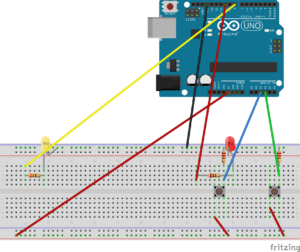
My project, Mani-Drive, consists of a robot car controlled by an Arduino board and a p5.js program. The robot car’s movements are controlled through a combination of hand tracking and user input via the p5.js program. The program utilizes the ml5.js library for hand tracking using a webcam. The position of the tracked hand determines the movement of the robot car. Moving the hand to the left, right, or forward commands the robot to move in the corresponding direction, while moving the hand downward makes the robot car move backward. The p5.js program communicates with the Arduino board via serial communication to control the robot’s movements. The circuit setup consists of the arduino uno board, basic wire connections, the DRV8833 Controller DC Motor driver, resistor, an ultrasonic sensor, four wheels, a buzzer, an LED and a bread board.The Arduino Uno board is responsible for motor control and obstacle detection. It uses an ultrasonic sensor to measure the distance to obstacles. If an obstacle is detected within a safe distance, the Arduino stops the robot’s movement, plays a sound using the buzzer, and turns on the LED as a warning. The Arduino code continuously checks the distance to handle object detection and resumes normal movement if no obstacles are detected. The Arduino board also receives commands from the p5.js program to control the robot’s movements based on the hand tracking data.

INTERACTION DESIGN

The interaction design of the project provides a user-friendly and intuitive experience for controlling and interacting with the robot car. By running the p5.js program and pressing the “s” key, the user initiates the program and activates hand tracking. The webcam captures the user’s hand movements, which are visually represented by a circular shape on the screen. Moving the hand left, right, up, or down controls the corresponding movement of the robot car. The color of the circular shape changes to indicate the intended movement direction, enhancing user understanding. Visual feedback includes a live video feed from the webcam and a warning message if an obstacle is detected. The Arduino board measures obstacle distances using an ultrasonic sensor and provides visual feedback through an LED and auditory feedback through a buzzer to alert the user about detected obstacles. This interactive design empowers users to control the robot car through natural hand gestures while receiving real-time visual and auditory feedback, ensuring a seamless and engaging interaction experience.

CODE(ARDUINO)

// Pin definitions for motor control
const int ain1Pin = 3;
const int ain2Pin = 4;
const int pwmaPin = 5;

const int bin1Pin = 8;
const int bin2Pin = 7;
const int pwmbPin = 6;

const int triggerPin = 9;      // Pin connected to the trigger pin of the ultrasonic sensor
const int echoPin = 10;        // Pin connected to the echo pin of the ultrasonic sensor
const int safeDistance = 10;   // Define a safe distance in centimeters

const int buzzerPin = 11;      // Pin connected to the buzzer
const int ledPin = 2;          // Pin connected to the LED

long duration;
int distance;
bool isBraking = false;

void setup() {
  // Configure motor control pins as outputs
  pinMode(ain1Pin, OUTPUT);
  pinMode(ain2Pin, OUTPUT);
  pinMode(pwmaPin, OUTPUT);
  pinMode(bin1Pin, OUTPUT);
  pinMode(bin2Pin, OUTPUT);
  pinMode(pwmbPin, OUTPUT);

  // Initialize the ultrasonic sensor pins
  pinMode(triggerPin, OUTPUT);
  pinMode(echoPin, INPUT);

  // Initialize the buzzer pin
  pinMode(buzzerPin, OUTPUT);

  // Initialize the LED pin
  pinMode(ledPin, OUTPUT);

  // Initialize serial communication
  Serial.begin(9600);
}

void loop() {
  // Measure the distance
  digitalWrite(triggerPin, LOW);
  delayMicroseconds(2);
  digitalWrite(triggerPin, HIGH);
  delayMicroseconds(10);
  digitalWrite(triggerPin, LOW);

  duration = pulseIn(echoPin, HIGH);

  // Calculate the distance in centimeters
  distance = duration * 0.034 / 2;

  // Handle object detection
  if (distance <= safeDistance) {
    if (!isBraking) {
      isBraking = true;
      stopRobot();
      playNote();
      digitalWrite(ledPin, HIGH);  // Turn on the LED when braking
    }
  } else {
    isBraking = false;
    digitalWrite(ledPin, LOW);     // Turn off the LED when not braking

    // Continue with normal movement
    if (Serial.available() > 0) {
      char command = Serial.read();

      // Handle movement commands
      switch (command) {
        case 'L':
          moveLeft();
          break;
        case 'R':
          moveRight();
          break;
        case 'U':
          moveForward();
          break;
        case 'D':
          moveBackward();
          break;
        case 'S':
          stopRobot();
          break;
      }
    }
  }
}

// Move the robot left
void moveLeft() {
  digitalWrite(ain1Pin, HIGH);
  digitalWrite(ain2Pin, LOW);
  analogWrite(pwmaPin, 0);
  digitalWrite(bin1Pin, HIGH);
  digitalWrite(bin2Pin, LOW);
  analogWrite(pwmbPin, 255);
}

// Move the robot right
void moveRight() {
  digitalWrite(ain1Pin, LOW);
  digitalWrite(ain2Pin, HIGH);
  analogWrite(pwmaPin, 255);
  digitalWrite(bin1Pin, LOW);
  digitalWrite(bin2Pin, HIGH);
  analogWrite(pwmbPin, 0);
}

// Move the robot forward
void moveForward() {
  digitalWrite(ain1Pin, LOW);
  digitalWrite(ain2Pin, HIGH);
  analogWrite(pwmaPin, 255);
  digitalWrite(bin1Pin, HIGH);
  digitalWrite(bin2Pin, LOW);
  analogWrite(pwmbPin, 255);

}

// Move the robot backward
void moveBackward() {

 digitalWrite(ain1Pin, HIGH);
  digitalWrite(ain2Pin, LOW);
  analogWrite(pwmaPin, 255);
  digitalWrite(bin1Pin, LOW);
  digitalWrite(bin2Pin, HIGH);
  analogWrite(pwmbPin, 255);

  // Check the distance after moving backward
  delay(10);  // Adjust this delay based on your needs

  // Measure the distance again
  digitalWrite(triggerPin, LOW);
  delayMicroseconds(2);
  digitalWrite(triggerPin, HIGH);
  delayMicroseconds(10);
  digitalWrite(triggerPin, LOW);
  duration = pulseIn(echoPin, HIGH);

  // Calculate the distance in centimeters
  int newDistance = duration * 0.034 / 2;

  // If an obstacle is detected, stop the robot
  if (newDistance <= safeDistance) {
    stopRobot();
    playNote();
    digitalWrite(ledPin, HIGH);  // Turn on the LED when braking
  }
  else {
    digitalWrite(ledPin, LOW);   // Turn off the LED when not braking
  }
}

// Stop the robot
void stopRobot() {
  digitalWrite(ain1Pin, LOW);
  digitalWrite(ain2Pin, LOW);
  analogWrite(pwmaPin, 0);
  digitalWrite(bin1Pin, LOW);
  digitalWrite(bin2Pin, LOW);
  analogWrite(pwmbPin, 0);
}

// Play a note on the buzzer
void playNote() {
  // Define the frequency of the note to be played
  int noteFrequency = 1000;  // Adjust this value to change the note frequency

  // Play the note on the buzzer
  tone(buzzerPin, noteFrequency);
  delay(500);  // Adjust this value to change the note duration
  noTone(buzzerPin);
}

DESCRIPTION OF CODE

The code begins by defining the pin assignments for motor control, ultrasonic sensor, buzzer, and LED. These pins are configured as inputs or outputs in the setup() function, which initializes the necessary communication interfaces and hardware components.

The core functionality is implemented within the loop() function, which is executed repeatedly. Within this function, the distance to any obstacles is measured using the ultrasonic sensor. The duration of the ultrasonic pulse is captured and converted into distance in centimeters. This distance is then compared to a predefined safe distance.

If an object is detected within the safe distance, the robot enters a braking mode. The stopRobot() function is called to stop its movement by setting the appropriate motor control pins and turning off the motors. The playNote() function is called to emit an audible alert using the buzzer, and the LED is illuminated by setting the corresponding pin to high.

On the other hand, if no objects are detected within the safe distance, the robot continues with normal movement. It waits for commands received through serial communication. These commands correspond to different movement actions:

moveLeft(): This function is called when the command ‘L’ is received. It sets the motor control pins to make the robot turn left by activating the left motor in one direction and the right motor in the opposite direction.

moveRight(): This function is called when the command ‘R’ is received. It sets the motor control pins to make the robot turn right by activating the left motor in the opposite direction and the right motor in one direction.

moveForward(): This function is called when the command ‘U’ is received. It sets the motor control pins to make the robot move forward by activating both motors in the same direction.

moveBackward(): This function is called when the command ‘D’ is received. It sets the motor control pins to make the robot move backward by activating both motors in the opposite direction. After a small delay, it performs an additional obstacle check by measuring the distance using the ultrasonic sensor. If an obstacle is detected, the stopRobot() function is called, and the playNote() function emits an audible alert. The LED is also illuminated.

stopRobot(): This function is called to stop the robot’s movement. It sets all motor control pins to low and stops the motors by setting the PWM value to 0.

playNote(): This function is called to generate tones on the buzzer. The frequency and duration of the played note can be adjusted by modifying the variables within the function. It uses the tone() and noTone() functions to play the note and pause the sound, respectively.

The modular structure of the code, with separate functions for each movement action, allows for easier maintenance and future enhancements. The implementation enables the robot car to navigate its environment, detect obstacles, and take appropriate actions for collision avoidance. It showcases the integration of hardware components with the Arduino microcontroller and demonstrates the practical application of sensor-based control in robotics.

P5.js CODE( For hand detection and movement of robot )

function gotHands(results = []) {
if (!programStarted && results.length > 0) {
const hand = results[0].annotations.indexFinger[3];
handX = hand[0];
handY = hand[1];

// Start the program when hand is detected and 's' is pressed
if (handX && handY && keyIsPressed && (key === 's' || key === 'S')) {
  programStarted = true;
  startRobot();
}
} else if (results.length > 0) {
const hand = results[0].annotations.indexFinger[3];
handX = hand[0];
handY = hand[1];
} else {
handX = null;
handY = null;
}
}

function moveLeft() {
if (isConnected) {
serial.write('L');
}
}

function moveRight() {
if (isConnected) {
serial.write('R');
}
}

function moveForward() {
if (isConnected) {
serial.write('U');
}
}

function moveBackward() {
if (isConnected) {
serial.write('D');
}
}

function stopRobot() {
if (isConnected) {
serial.write('S');
}
}

function startRobot() {
// Start the robot movement when the hand tracking model is ready
console.log('Hand tracking model loaded');
}

// Function to detect obstacle
function detectObstacle() {
obstacleDetected = true;
carMovingBack = true;
}

// Function to stop obstacle detection
function stopObstacleDetection() {
obstacleDetected = false;
carMovingBack = false;
}

DESCRIPTION OF P5.js code

The code starts by declaring variables such as isConnected, handX, handY, video, handpose, obstacleDetected, carMovingBack, and programStarted. These variables are used to track the connection status, hand coordinates, video capture, hand tracking model, obstacle detection status, and program status.

In the preload() function, images for the instructions and introduction screen are loaded using the loadImage() function.

The keyPressed() function is triggered when a key is pressed. In this case, if the ‘s’ key is pressed, the programStarted variable is set to true, and the startRobot() function is called.

The setup() function initializes the canvas and sets up the serial communication with the Arduino board using the p5.serialport library. It also creates a video capture from the webcam and initializes the hand tracking model from the ml5.handpose library. The gotHands() function is assigned as the callback for hand tracking predictions.

The introScreen() function displays the introduction screen image using the image() function, and the instructions() function displays the instructions image.

The draw() function is the main loop of the program. If the programStarted variable is false, the intro screen is displayed, and the function returns to exit the draw loop. Otherwise, the webcam video is displayed on the canvas.

If the handX and handY variables have values, an ellipse is drawn at the position of the tracked hand. Based on the hand position, different movement commands are sent to the Arduino board using the moveLeft(), moveRight(), moveForward(), and moveBackward() functions. The color of the ellipse indicates the direction of movement.

The code checks if the hand position is out of the frame and stops the robot’s movement in that case. It also checks for obstacle detection and displays a warning message on the canvas if an obstacle is detected.

The gotHands() function is the callback function for hand tracking predictions. It updates the handX and handY variables based on the detected hand position. If the programStarted variable is false and a hand is detected while the ‘s’ key is pressed, the programStarted variable is set to true, and the startRobot() function is called.

The moveLeft(), moveRight(), moveForward(), moveBackward(), and stopRobot() functions are responsible for sending corresponding commands to the Arduino board through serial communication.

The startRobot() function is called when the hand tracking model is loaded successfully. Currently, it only logs a message to the console.

The detectObstacle() function sets the obstacleDetected and carMovingBack variables to true, indicating an obstacle has been detected and the robot should move back.

The stopObstacleDetection() function resets the obstacleDetected and carMovingBack variables, indicating the obstacle has been cleared and the robot can resume normal movement.

PARTS I’M PROUD OF AND FUTURE IMPROVEMENTS

The most obvious part of the project that i’m very proud of is how i got to implement the hand tracking library into the code to make it work even though it has some minor control bugs. Initially, i started off by setting the control system to the arrow keys on the keyboard and after i got that to work, i went ahead to integrate the ml5.js library into the code to track the user’s hands through the webcam and then map the movement of the hands to the corresponding arrow keys to make the robot move. Future improvements include making the whole arduino setup work with the p5.js part wirelessly to allow free movement of the car and also improving the implementation  and integration of the hand tracking model to ensure accurate response to the movement s of the user’s hands. I also intend to add an LCD screen and also more LED lights to make it very similar to how an actual car looks.

FINAL PROJECT PROPOSAL

CONCEPT

For now, my plan is to build a car which will be controlled using hand gestures from the user. To do this, the control system will track the user’s hand position, interpret the hand gestures made by the user and translated the hand gestures into commands that’d be used in moving the car. To add up to the obstacle detection features of the car, i will use the ultrasonic sensor. The ultrasonic sensor would detect the distance between the car and obstacles and i will have the minimum distance set at a value so the car automatically undergoes rerouting.

IMPLEMENTATION

My goal is to develop a control system for a car by integrating the P5JS tracking system. This system will enable the car to be controlled through hand gestures made by the user. To achieve this, I will utilize the advanced capabilities of PoseNet for detecting the user’s hand position accurately. By interpreting the hand gestures made by the user, the system will translate them into commands that can be used to move the car.

The P5JS tracking system will be responsible for monitoring and analyzing the forward and backward movements of the user’s hand to control the car accordingly. It will allow the user to steer the car in the desired direction by moving their hand forward, backward, left or right. The tracking system will accurately detect the user’s hand position and interpret the hand gestures in real-time, enabling seamless and responsive control of the car.


FINAL PROJECT IDEA

CONCEPT

For now, my plan is to build a car which will be controlled using hand gestures from the user. To do this, the control system will track the user’s hand position, interpret the hand gestures made by the user and translated the hand gestures into commands that’d be used in moving the car.

IMPLEMENTATION

My goal is to develop a control system for a car by integrating the P5JS tracking system. This system will enable the car to be controlled through hand gestures made by the user. To achieve this, I will utilize the advanced capabilities of PoseNet for detecting the user’s hand position accurately. By interpreting the hand gestures made by the user, the system will translate them into commands that can be used to move the car.

The P5JS tracking system will be responsible for monitoring and analyzing the forward and backward movements of the user’s hand to control the car accordingly. It will allow the user to steer the car in the desired direction by moving their hand forward, backward, left or right. The tracking system will accurately detect the user’s hand position and interpret the hand gestures in real-time, enabling seamless and responsive control of the car.


WEEK 11

PROMPT 1

Code

//declaring variables
let serial;
let photoValue = 0;
let xPos = 0;
let Size = 80;
let yPos = 200;

function setup() {
  createCanvas(400, 400);
  serial = new p5.SerialPort();
  serial.open('/dev/tty.usbmodem1301');
  serial.on('data', readSerialData); // call readSerialData when new data is received
}

function draw() {
  background(220);
  fill("red");
  ellipse(xPos, yPos, Size, Size);
}

function readSerialData() {
  let data = serial.readLine(); // read the incoming data
  if (data) {
    photoValue = Number(data); // convert the data to a number
    xPos = map(photoValue, 0, 1023, 0, width); // map the photo sensor value to the x-position of the ellipse
  }
}

Video


PROMPT 2

CODE

let serial;
let brightness = 0; // variable to store LED brightness

function setup() {
  serial = new p5.SerialPort();
  serial.open('/dev/tty.usbmodem1301');
  createCanvas(400, 400);
}

function draw() {
  background(220);
  text("LED Brightness: " + brightness, 50, 50);

  // send data to Arduino over serial
  if (frameCount % 10 == 0) {
    serial.write(brightness);
  }
}

function keyPressed() {
  if (keyCode === UP_ARROW && brightness < 255) {
    brightness += 10; // increase brightness by 10
  } else if (keyCode === DOWN_ARROW && brightness > 0) {
    brightness -= 10; // decrease brightness by 10
  }
}

VIDEO


PROMPT 3

CODE

let gravity;
let position;
let acceleration;
let wind;
let drag = 0.99;
let mass = 50;
let lightVal = 0;
let ledState = false;

let serial;
let led;

function setup() {
  createCanvas(640, 360);
  noFill();
  position = createVector(width/2, 0);
  velocity = createVector(0,0);
  acceleration = createVector(0,0);
  gravity = createVector(0, 0.5*mass);
  wind = createVector(0,0);

  serial = new p5.SerialPort();
  serial.open('/dev/tty.usbmodem1301');
  serial.on("data", serialEvent);

  led = new p5.SerialPort();
  led.open('/dev/tty.usbmodem1301');
}

function draw() {
  background(255);

  wind.x = map(lightVal, 0, 1023, -1, 1);

  applyForce(wind);
  applyForce(gravity);
  velocity.add(acceleration);
  velocity.mult(drag);
  position.add(velocity);
  acceleration.mult(0);
  ellipse(position.x,position.y,mass,mass);

  if (position.y > height-mass/2) {
    velocity.y *= -0.9;  // A little dampening when hitting the bottom
    position.y = height-mass/2;
    led.write("L"); // Turn off the LED when the ball hits the ground
  } else {
    led.write("H"); // Turn on the LED when the ball is in the air
  }
}

function applyForce(force){
  // Newton's 2nd law: F = M * A
  // or A = F / M
  let f = p5.Vector.div(force, mass);
  acceleration.add(f);
}

function serialEvent() {
  lightVal = Number(serial.readLine());
}

function keyPressed(){
  if (keyCode==LEFT_ARROW){
    wind.x=-1;
  }
  if (keyCode==RIGHT_ARROW){
    wind.x=1;
  }
  if (key==' '){
    mass=random(15,80);
    position.y=-mass;
    velocity.mult(0);
  }
}

VIDEO


Musical Instrument

Concept

In this assignment, we were to create musical instruments but in groups. I could not find someone to work with so i decided to work on my own. One other reason was that i wanted to also have time to explore and learn more. My musical instrument is a basic one which uses two external libraries that are adapted for the ultrasonic sensor and the piezo buzzer. The libraries are the NewPing.h and the ToneAC.h library. The NewPing.h library is adapted to work with all types of ultrasonic sensors and increases the accuracy of the distance calculated. The ToneAC library has a higher frequency range, twice the volume and higher quality than the tone library. By combining these two libraries my instrument improved a lot more and had better quality sounds.

#include <NewPing.h> // newping library for the ultrasonic sensor
#include <toneAC.h> // tine library for the piezo buzzer

//pins of the ultrasonic sensor
const int trig=12; 
const int echo=11;

NewPing sonar( trig, echo, 35 ); // creating a new class for the ultrasonic sensor

void setup() {
  // put your setup code here, to run once:
Serial.begin(9600); // for debugging and printing the values stored
}


void loop() {
  // put your main code here, to run repeatedly:
  //calculate the distance to the obstacle
int f= sonar.ping_cm();
Serial.print("freq");
Serial.println(f);


//map the distance calculated to the notes c1 to e7
int frequency =map(f, 0, 35, 33, 4000);

//play the sound on the buzzer
toneAC(frequency, 10);

delay(200);
}


Week 9- SWITCHES AND LED LIGHTS

Concept

For this assignment, I had two LEDs which would be controlled by two switches. When the switches are pressed either individually or together, the LEDs are turned on in different ways.  First, pressing the swiitches one by one would turn on their corresponding LEDs and when they are pressed together, the LEDs light up, blinking in a pattern.

Diagram

CODE

void setup() {
  pinMode(8, OUTPUT);
  pinMode(13, OUTPUT);
  pinMode(A2, INPUT);
  pinMode(10, OUTPUT);
  pinMode(13, OUTPUT);
  pinMode(A3, INPUT);
}

void loop() {

  int switchPosition = digitalRead(A2);
  int switch2Position = digitalRead(A3);

  if (switchPosition == HIGH) { 
    digitalWrite(8, HIGH);   // turn the LED on (HIGH is the voltage level)
    digitalWrite(13, LOW);
  } else  {
    digitalWrite(8, LOW);    // turn the LED off by making the voltage LOW
    digitalWrite(13, HIGH);
  }
 if (switch2Position == HIGH) {
    digitalWrite(10, HIGH);   // turn the LED on (HIGH is the voltage level)
    digitalWrite(13, LOW);
  } else  {
    digitalWrite(10, LOW);    // turn the LED off by making the voltage LOW
    digitalWrite(13, HIGH);
  }


  if (switchPosition == HIGH && switch2Position == HIGH) {
   digitalWrite(8, HIGH); // turn the LED on (HIGH is the voltage level)
   delay(200); // wait 0.2 seconds before turning off the LED 
   digitalWrite(8, LOW); // turn the LED off by making the voltage LOW
   delay(200); // wait 0.2 seconds before turning on the LED

   
  digitalWrite(10, LOW); // turn the LED off by making the voltage LOW
  delay(200); // wait 0.2 seconds before turning on the LED
  digitalWrite(10, HIGH); // turn the LED on (HIGH is the voltage level)
  delay(200); // wait 0.2 seconds before turning off the LED 
  
  }
 

}

VIDEO

Week 8- Unusual Switch

IDEA DEVELOPMENT

To answer the prompt of this assignment, my goal was to create a simple circuit with an usual switch which would open or close the circuit while being creative  with my idea. I spent sometime thinking of what i could possibly do that’d be unusual.  I was finally able to come up with an idea- to use equipment readily available to me( a cup and teaspoon )

VIDEO


Concept

The circuit is just a basic one made up of wires, a resistor, power source( arduino. board ), an LED, a bread board and a switch. The switch is the only unusual thing about the circuit. Since a switch is anything capable of opening or closing the circuit, i decided to go with a teaspoon and a cup of water. This was to make use of the fact that metals and water are good conductors of electricity. I had the wires ( one connecting to the anode metal strip of the LED and the other connected to the cathode strip ) connected to the spoon and one in the cup containing the water. When the spoon is placed in the cup containing the water, the circuit becomes a closed conducting path which allows the flow of charges to the LED and then it turns on.

Midterm Project Documentation(Hit the Island Game)

IDEA

For my midterm project, I decided to create a game out of the options from which we could choose any to create a project. A game that would use all the concepts learned in class so far. I got my inspiration from a game on the apple app store called “Hit the Island”. I always wondered how the game was created and how the developers got it to be interactive with the dynamic island on the iPhone 14 pro series. After taking this class, I have gained enough knowledge to know that the game doesn’t actually interact with the dynamic island but has a bar-shaped object behind the island with which the balls in the game interact.

ORIGINAL GAME

The original game below was developed by Funn Media, LLLC.

Code Structure:
The code is structured into several functions that are responsible for different parts of the game. The main functions are as follows:

createPaddles() – This function creates two paddles, one at the top of the canvas and the other at the bottom.

resetGame() – This function resets the game by clearing the balls array and calling createPaddles() to create new paddles.

setup() – This function initializes the game by creating a canvas, calling resetGame(), and loading images and sounds.

preload() – This function loads images and sounds before the game starts.

introScreen() – This function displays the intro screen with the game title.

endScreen() – This function displays the end screen with the player’s score.

gameplay() – This function handles the main gameplay loop by updating the ball’s position, checking for collisions with walls and paddles, and removing balls that fall off the canvas.

checkKeyPressed() – This function checks for keyboard input and moves the paddle left or right, and launches the ball.

Ball class – This class represents the ball in the game and handles its movement, collision detection, and rendering.

Paddle class – This class represents a paddle in the game and handles its movement, collision detection, and rendering.

How the game is played(functionality)
The game starts with the intro screen and waits for the player to press the “s” key to start the game. Once the game starts, the player can move the paddle left or right using the left and right arrow keys.  The ball bounces off the paddles and the walls of the canvas, and the player scores points by hitting the ball with the top paddle. The game ends when the player loses all their lives, and the end screen displays the player’s score. The player can restart the game by pressing the “p” key or return to the intro screen by pressing the “q” key.

GAME


CODE SNIPPETS

Main gameplay code

CHALLENGES AND FUTURE IMPROVEMENTS

As at now, the game has a lot of bugs and is still in the “beta testing” phase. There are numerous errors to be fixed including the update of score when the ball hits the top paddle, playing of ball sound when the ball hits the roof of the canvas, and the general collision between the ball and the paddles. In a next update, i intend to fix these errors and also add more levels, varying ball speed and increasing the number of balls when the user gets to a certain score.


ASSIGNMENT 5- MIDTERM PROJECT PROGRESS

IDEA

For my midterm project, I decided to create a game out of the options from which we could choose any to create a project. A game that would use all the concepts learned in class so far. I got my inspiration from a game on the apple app store called “Hit the Island”. I always wondered how the game was created and how the developers got it to be interactive with the dynamic island on the iPhone 14 pro series. After taking this class, I have gained enough knowledge to know that the game doesn’t actually interact with the dynamic island but has a bar-shaped object behind the island with which the balls in the game interact.

ORIGINAL GAME


The original game below was developed by Funn Media, LLLC.

UI DESIGN

This is the basic form which i want my game to take. On a surface level, the game basically consists of a paddle, a ball and another paddle on top of the screen which i call the island. In the game, the paddle is controlled using the left and right arrow keys. Every time the ball hits the island, the user gains a point. The game ends when the balls fall off the screen.  The game has three different pages. The intro page, the game page and the end page. In the intro page, the user has the option to start the game or quit the game. In the end page or game-over page, which shows after the user has lost the game, the user has the option to restart the game or quit as well.

PROGRESS SO FAR

So far, I have the basic game page set up with the balls and the user-paddle. I also have placeholders( which are basic color backgrounds ) set in place for the intro page and the end page which i am yet to design in either photoshop or illustrator.


CHALLENGES SO FAR AND INTENDED UPDATE

I haven’t encountered any major challenges so far. This is my progress as at now and in the final version of my game, i intend to to have two paddles, the moveable one which i have now and a static one (the island) at the top of the screen just as the original game. Every time the ball hits the paddles, there will be a sound feedback to improve the overall experience of the game. There will also be a background sound and an option for the user to mute the sound in the game or to keep it playing.