
Concept
It’s November already! Unbelievable. This means that we can start thinking about and preparing for Christmas more explicitly—and that includes decorations! Looking at the red and green LEDs, I was inspired by the festive thought of Christmas lights. With the idea to implement analog and digital sensors as controllers for the flickering of the lights, I set out to work.
Process
After a few iterations, I was able to settle on a setup that worked:
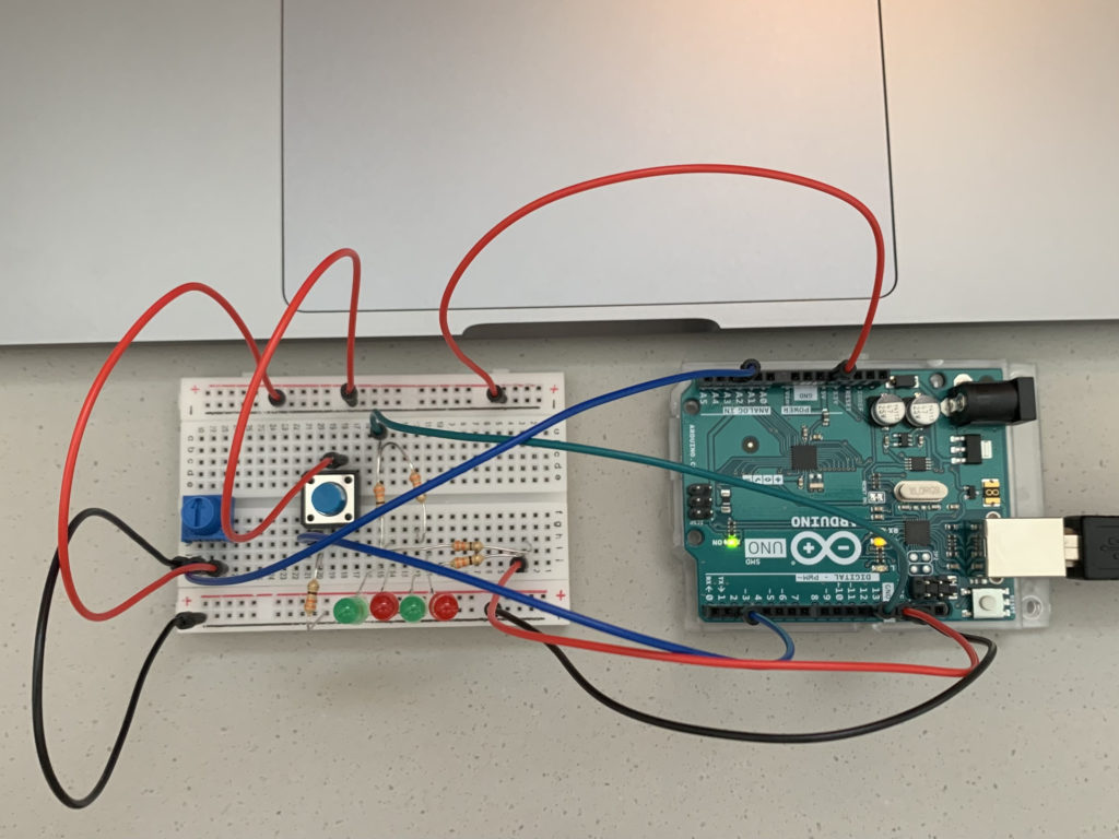
The row of four alternating red and green LEDs are the Christmas lights; the red LEDs are connected to Pin 13, while the green ones are connected to Pin 12. The colors of the wires match the colors of the connected LEDs. Electricity from the 5V pin flows to both the digital sensor (the switch) and the analog sensor (the potentiometer), from which data goes respectively to Pin 2 and the A2 pin. All of the circuits, of course, flow back to the GND pin.
As for the code, I first initialized the needed variables and got things started in the setup() function:
//Initialize Variables
int currentButtonState;
int lastButtonState;
int LEDState = 0;
int sensorValue;

void setup() {
  //Initialize Serial
  Serial.begin(9600);
  //Set Pins
  pinMode(12, OUTPUT);
  pinMode(13, OUTPUT);
  pinMode(2, INPUT);
  //Set the Starting State of the Button
  currentButtonState = digitalRead(2);
}
The currenButtonState and lastButtonState variables are crucial to a central feature of my circuit, which is how the button is used to switch between the LEDs’ three different modes (off, on, alternating blinks). For this part of the code, I referred to this tutorial: Arduino Button Toggle LED Tutorial.
The LED’s modes are linked to the LEDState variable; 0 is off, 1 is on, and 2 is alternating blinks. As shown in the code above, LEDState starts at 0, meaning the LEDs are initially off.
Following is the first part of the code in the loop() function:
void loop() {
  //Saves the Last State
  lastButtonState = currentButtonState;
  //Reads the New, Current State
  currentButtonState = digitalRead(2);
  //Sensor Value; 100 is the minimum for the delay interval
  sensorValue = analogRead(A2) + 100;
  Serial.println(sensorValue);
  //Delay for Read Stability
  delay(1);

  //Only Runs When Button is Pressed
  if (lastButtonState == HIGH && currentButtonState == LOW) {
    Serial.println("The button has been pressed.");
    //Change LED State with Each Press
    if (LEDState == 0){
      LEDState = 1;
  } else if (LEDState == 1){
      LEDState = 2;
  } else if (LEDState == 2){
      LEDState = 0;
  }
  //Rest of Code Below
}
As demonstrated in the code, an if statement is used t0 check if the button has been pressed—and when the button is pressed, a chain of nested if else statements are used to change the value of the LEDState variable to the next one in line. Also notable is how the sensorValue is used to store the value collected from the potentiometer with an extra 100 added to it. The reason for this is revealed in the rest of the code:
void loop() {
  //Rest of the Code Above
  //0 = Off; 1 = On; 2 = Alternating Blinks, Delay interval controlled by potentiometer
  if (LEDState == 0){
    digitalWrite(12, LOW);
    digitalWrite(13, LOW);
    }
  } else if (LEDState == 1){
    digitalWrite(12, HIGH);
    digitalWrite(13, HIGH);
  } else if (LEDState == 2){
    digitalWrite(12, HIGH);
    digitalWrite(13, LOW);
    delay(sensorValue);
    digitalWrite(12, LOW);
    digitalWrite(13, HIGH);
    delay(sensorValue);
  }
}
Based on the value of LEDState, a different mode is accessed. sensorValue is used as the parameter value in the delay() functions to determine the length of the interval of each blink; turning the potentiometer counterclockwise will make the LEDs blink quicker, while turning it clockwise will make them blink slower. 100 is added to the value from the potentiometer to determine sensorValue because I determined that 100 would be a good minimum value to set for the delay() function (a parameter of 0 would essentially be no blinking, while anything under 100 is much too rapid).
Here is a video of what the finished project looks like:
Reflections
While I initially struggled to grasp the workings of Arduino and circuits, I feel that I have begun to get a hang of how things work. Tinkering with the kit on my own has allowed me to review and figure things out, and being able to pull this off successfully has been a confidence boost! I feel much more comfortable with Arduino than I was prior to this assignment.
One major part of the project I could improve: using the delay() function has the critical drawback of rendering my program unable to read any button presses that happen while Arduino is paused (making it seem unresponsive). It turns out there is indeed a way to make the LEDs blink without using the delay() function, one that I only found out about after wrapping things up; it will be something to keep in mind as I continue to work with Arduino.