
Concept
My Project is to create a generative art piece controlled by sensors. I had a hard time figuring out a proper art. My idea was to create a firework-like design pop-up using sensors and change their features. I instead have 3 modes, first two modes include 2 brushes (an idea from my friend!) and generative art.
Implementation
Note: modes have to be changed manually in p5js
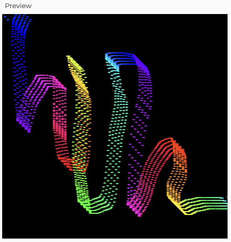
Brush 1-Line stroke of ellipses Mode 0
Basically, this brush stroke has a few ellipses lined up and it can be used to draw/paint across the screen. I used two potentiometers to control the x and y position of the brush on the screen.
Here’s how it looked upon moving:
I was inspired to make this brush stroke from this youtube video: https://www.youtube.com/watch?v=YhGoi5MNyvM
Brush-2 Blurry-Trace Brush Mode 1
There is a round brush on procreate that I absolutely love and it is also its signature brush (the ads use it often!) that I kinda re-created. I used a rectangle shape and rounded the corners and used vertical-gradient function code from the happy-coding website. Using the vertical gradient gave it a transparent blurry feel.
Here’s what it looks like: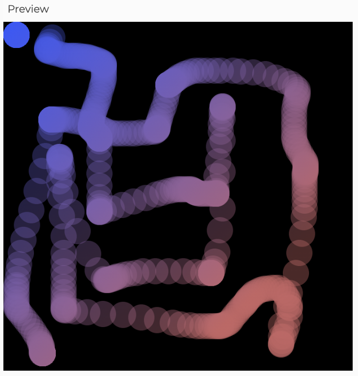
Vertical-Gradient function: https://happycoding.io/examples/p5js/for-loops/vertical-gradient
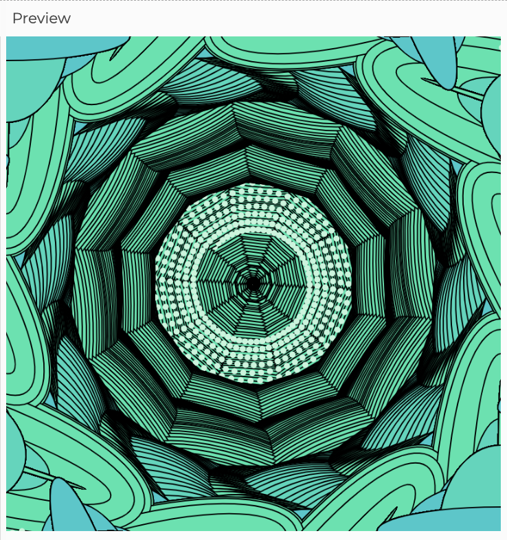
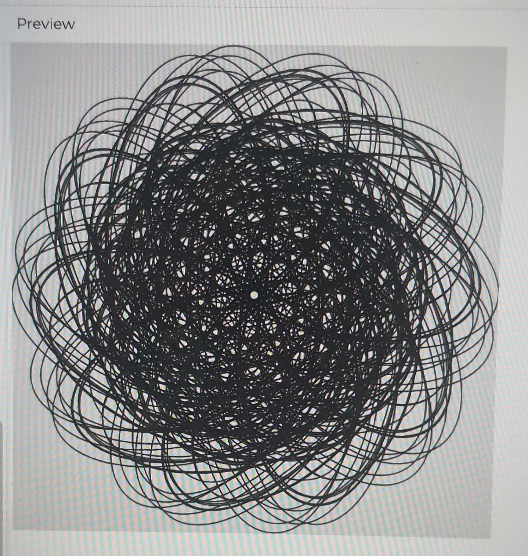
Generative Art
As mentioned in my previous posts, I wanted to have an ellipse positioned as a flower moving and increasing in size. So, I used them and kinda played around creating a camera shutter art. There was some space left in the middle and I spent a lot of time thinking about what to have here I tried having flow fields, bubbles, and noise objects. Finally, ended up with spiral movements and it looked cool. The X and Y position of ellipses was fixed and height and width were being controlled by the two potentiometers.
Here how it looks like:
What I made earlier; was generated by p5js and not controlled by Arduino: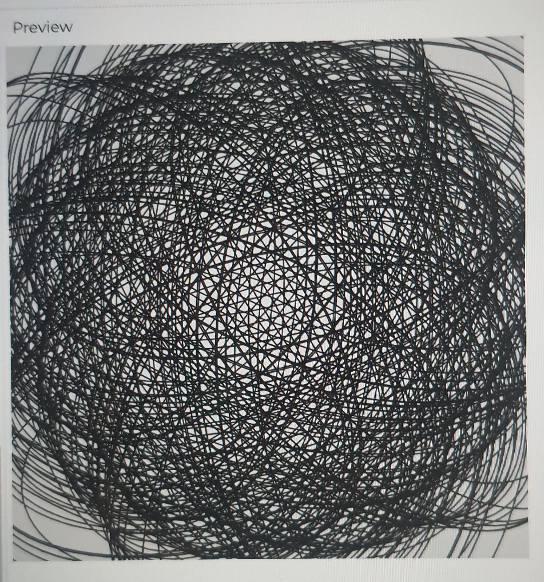
Code
p5js
To test, simply edit the code by replacing xpos, ypos values with mouseX, mouseY. Works similarly!
Arduino
void setup() {
 Serial.begin(9600); // initialize serial communications
}

void loop() {
 int p1 = analogRead(A0);
 int m = map(p1, 0, 1023, 0, 255);
 Serial.print(m);
 Serial.print(",");
 int p = analogRead(A5);
 int m2 = map(p, 0, 1023, 0, 255);
 Serial.print(m2);
 Serial.println();

}
Arduino Board
A0 pin potentiometer: X values
A1 pin potentiometer: Y values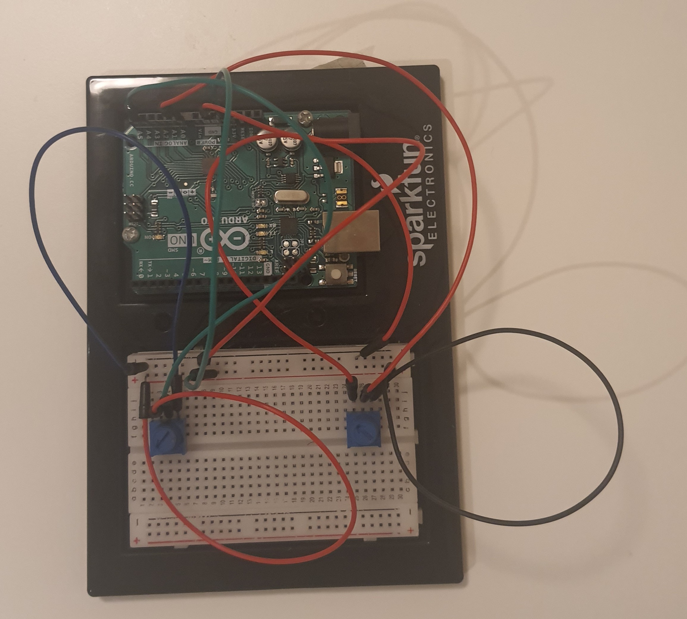
Challenges and Reflection
I had some hardware issues (i think? StackOverflow and Arduino forums mentioned some of them) initially and my serial communicator wasn’t reading the second potentiometer’s values at all. It wasn’t even accepting any second input. I used a comma to separate the value and upon reading I realized that even the comma wasn’t read (I mean Serial.print). I looked at multiple websites and then came to the Arduino/p5js related website by NYU ITP. And, then I would say a miracle, somehow my Arduino started accepting the second potentiometer and comma!!? So, I used split to split the string and access the printed data. Then I had some issues with the button that I wanted to use to switch the modes and then I gave up on it because I didn’t have time. One dumb thing I did was to make the p5js code and then connect Arduino at the very end. Should have worked simultaneously.
It was a fun project to do. While I had a hard time coming up with the idea, I really enjoyed experimenting with art! Realized well that art doesn’t have to be defined and constrained!!!
This was a great course! I took it because I wanted to minor in IM but I am considering a major now. This has really got me into the design.