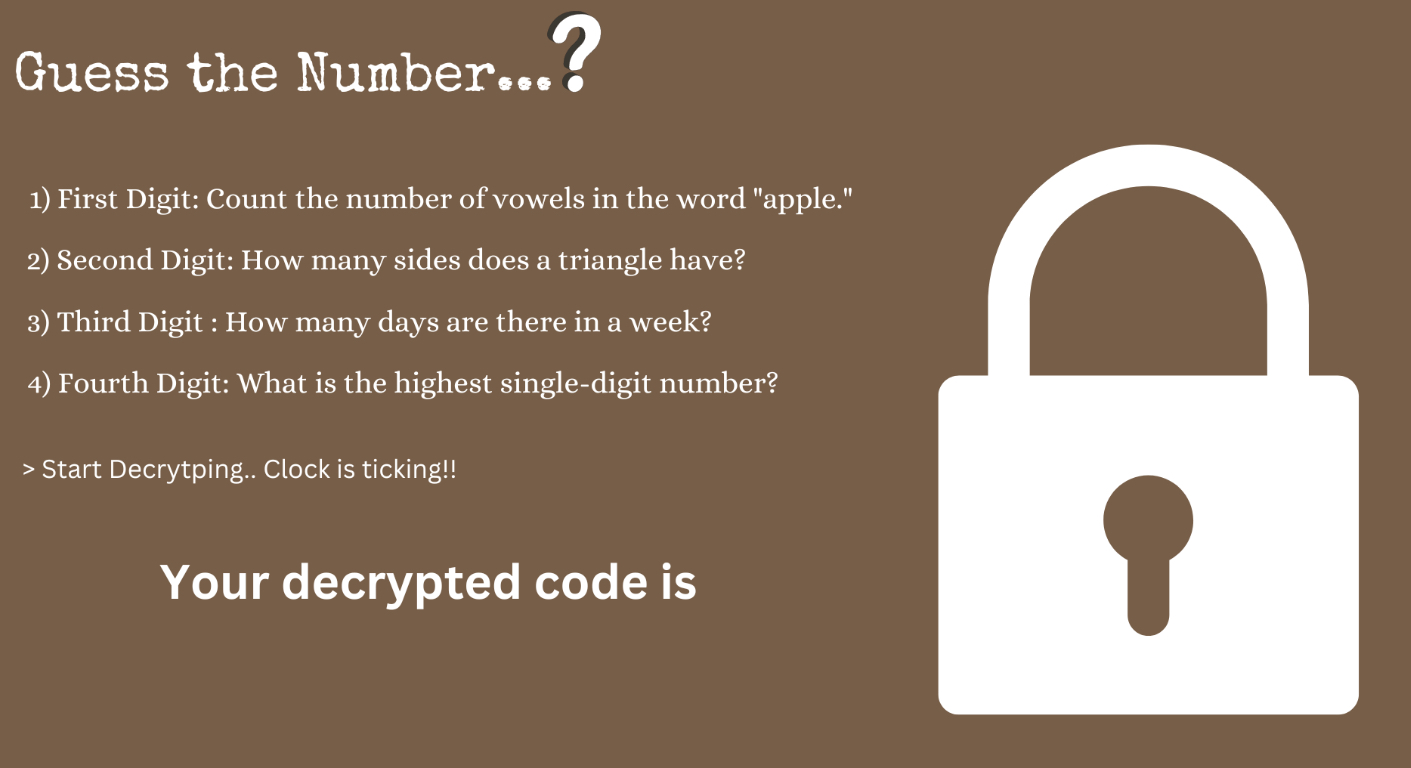
Concept Introduction : The Crypto Locker Puzzle is an interactive project designed to challenge users with a series of numbers-cracking tasks under time constraints. The objective is to solve hints and enter correct codes using a custom-built interface to unlock a cardboard box and win the prize inside. This game combines physical computing with digital elements to create an engaging and educational experience.
Link to P5.js Sketch: Click Here
Images of the project:
 Initial Design , Credits to Dall-E.
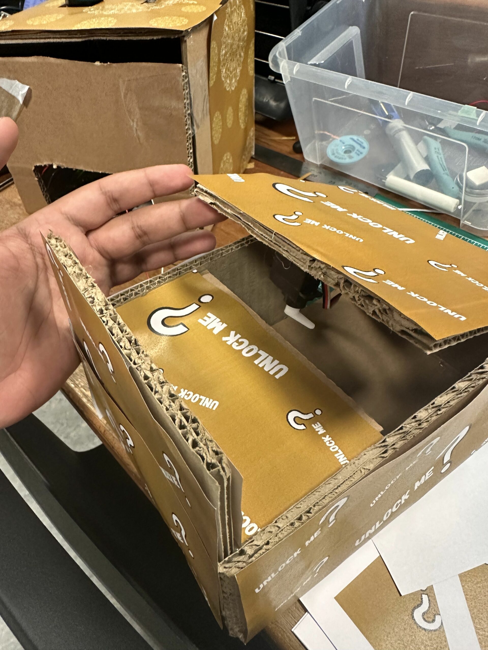 Image of the unlocked candy box
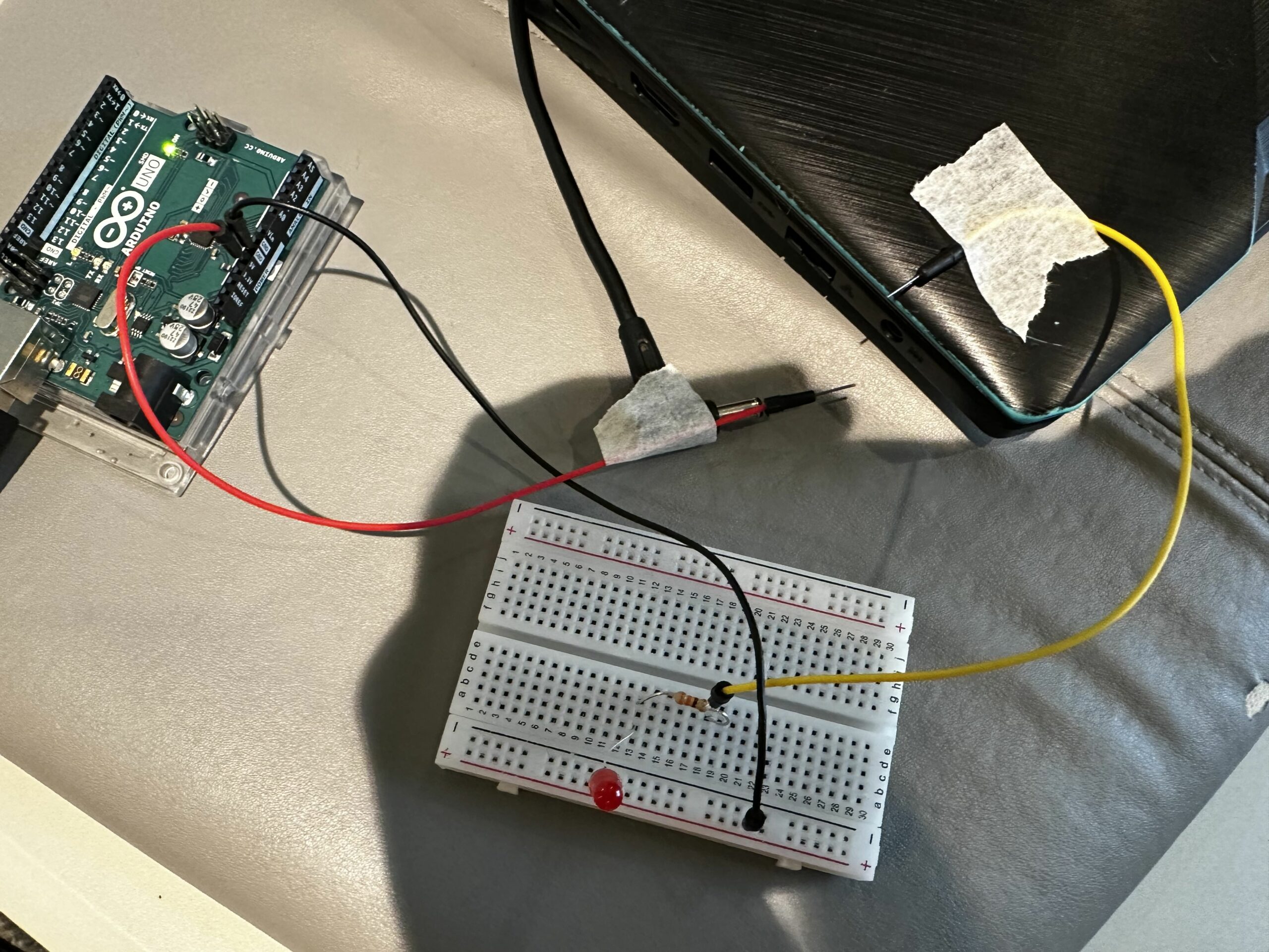
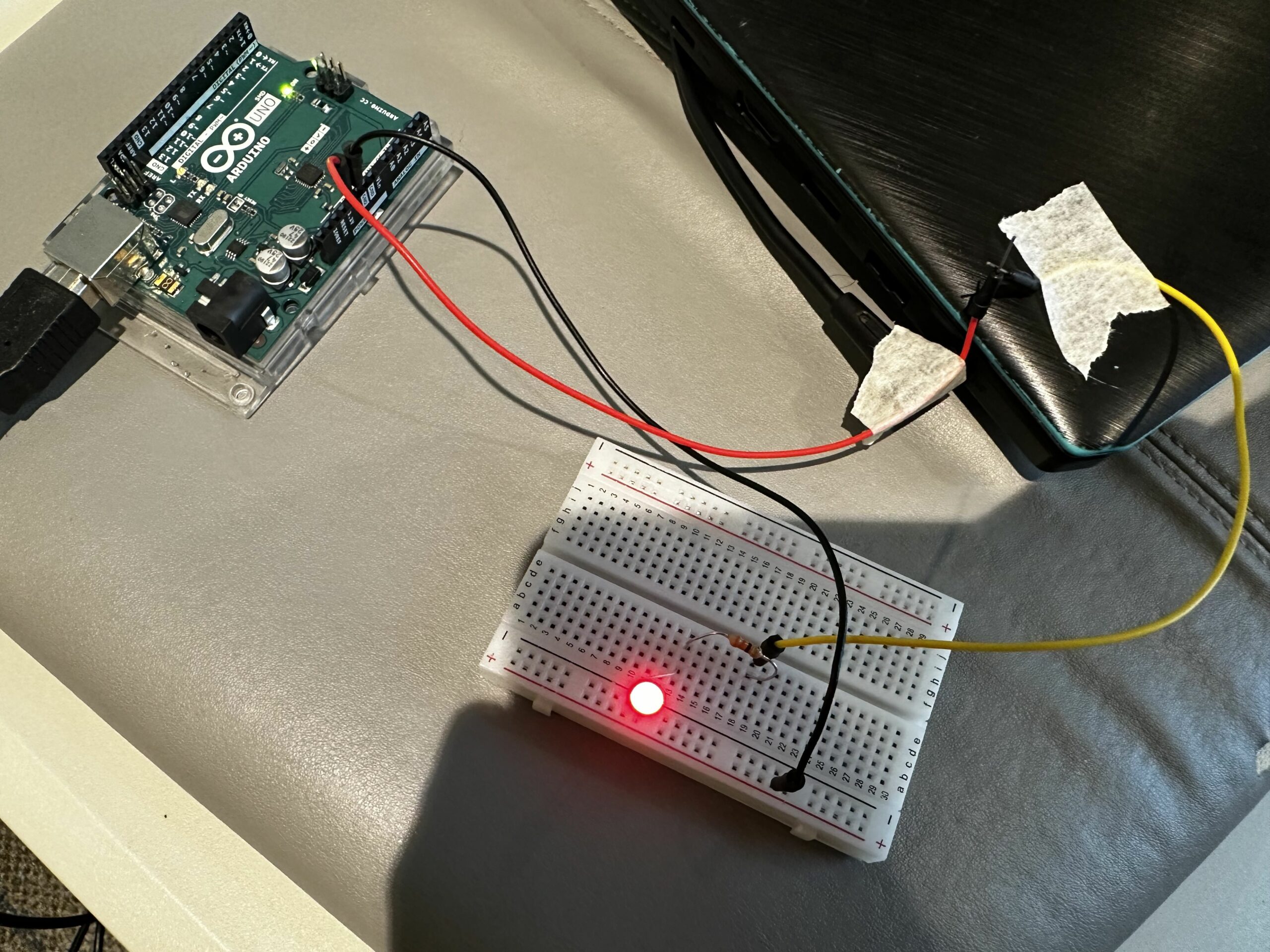
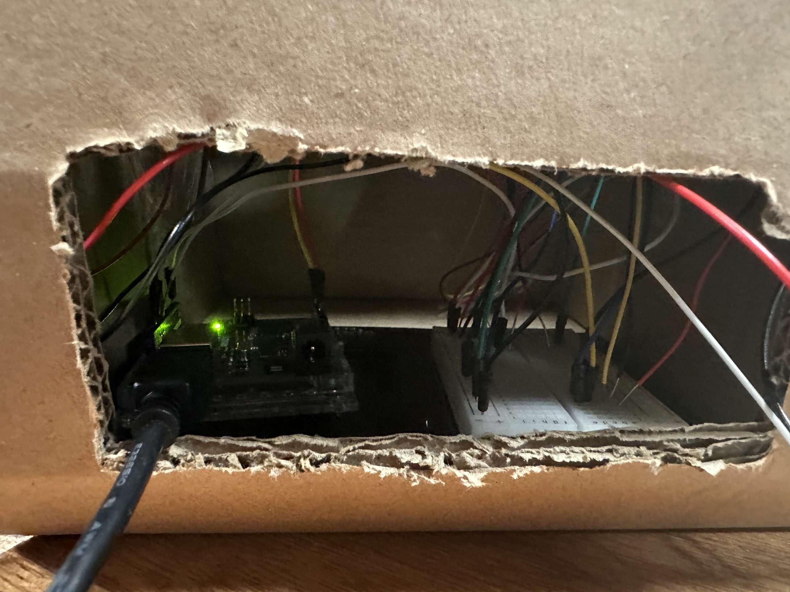 Image of the wirings and breadboard (backside)
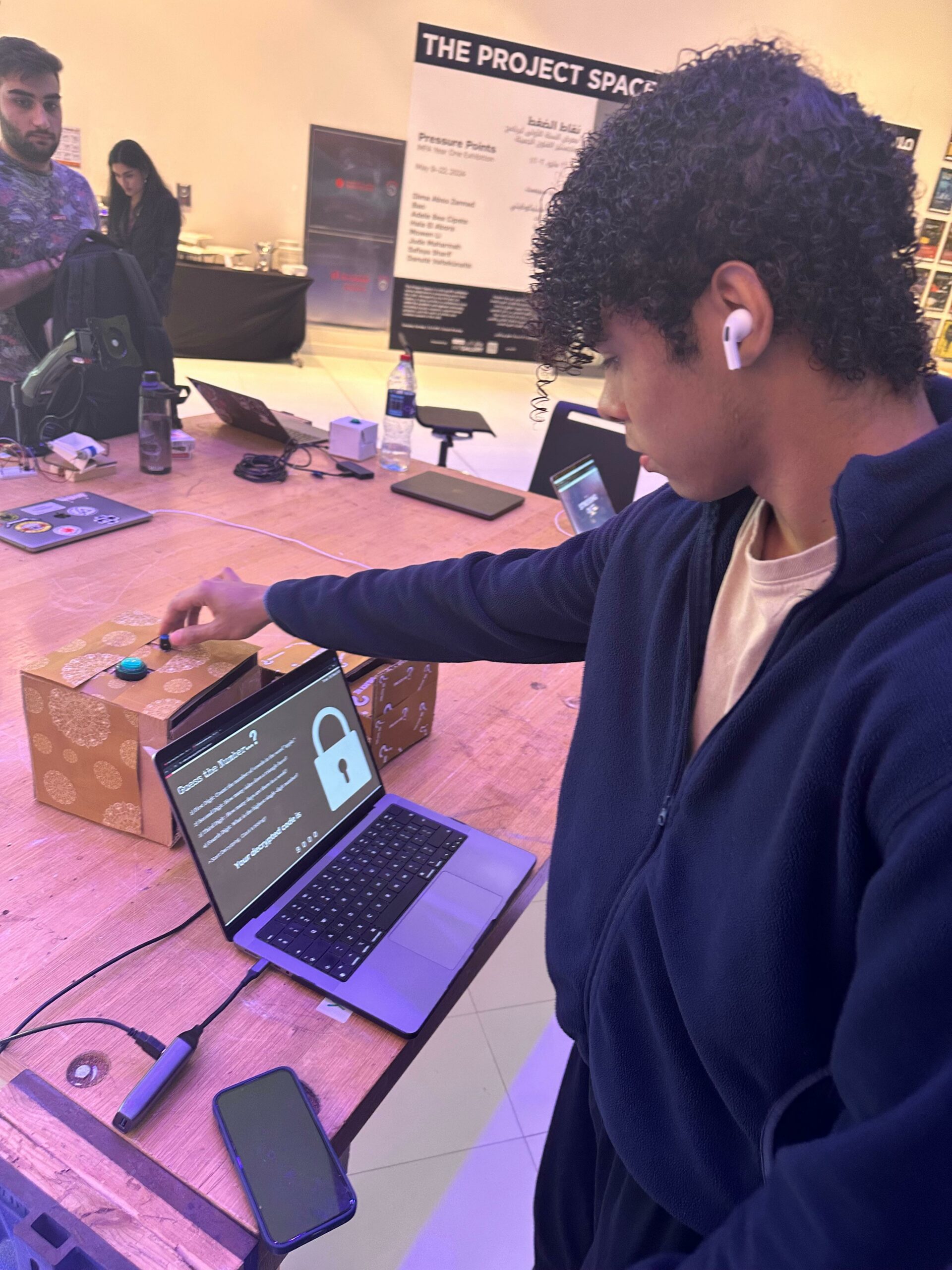
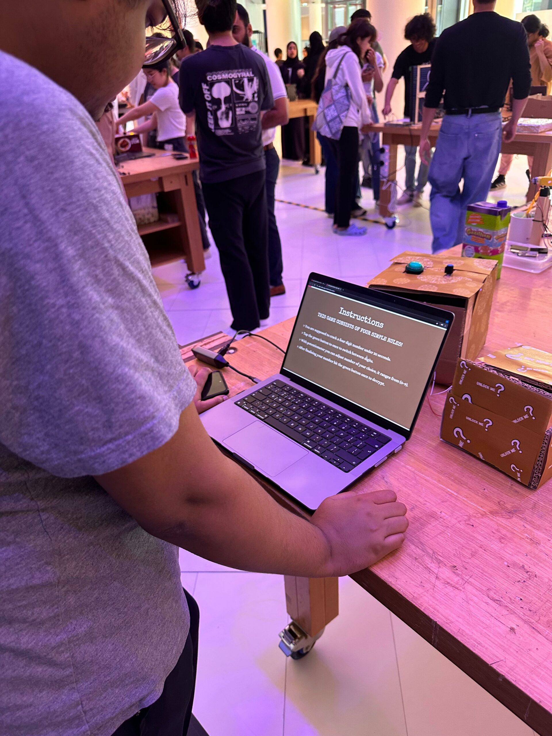
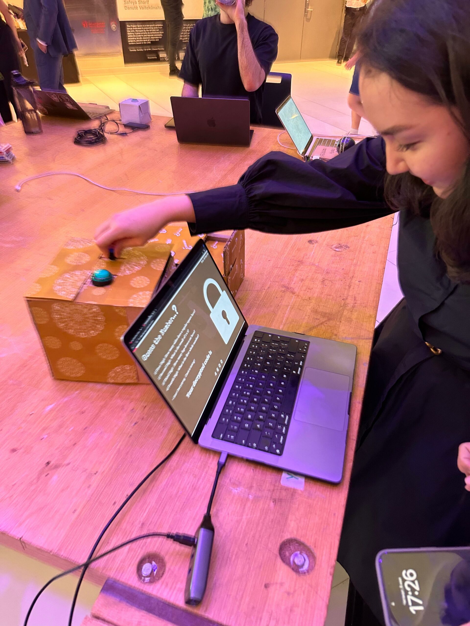
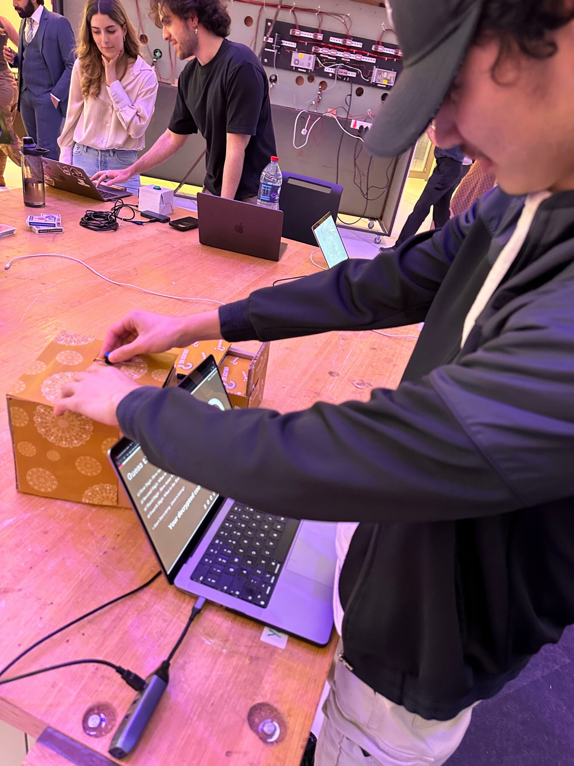
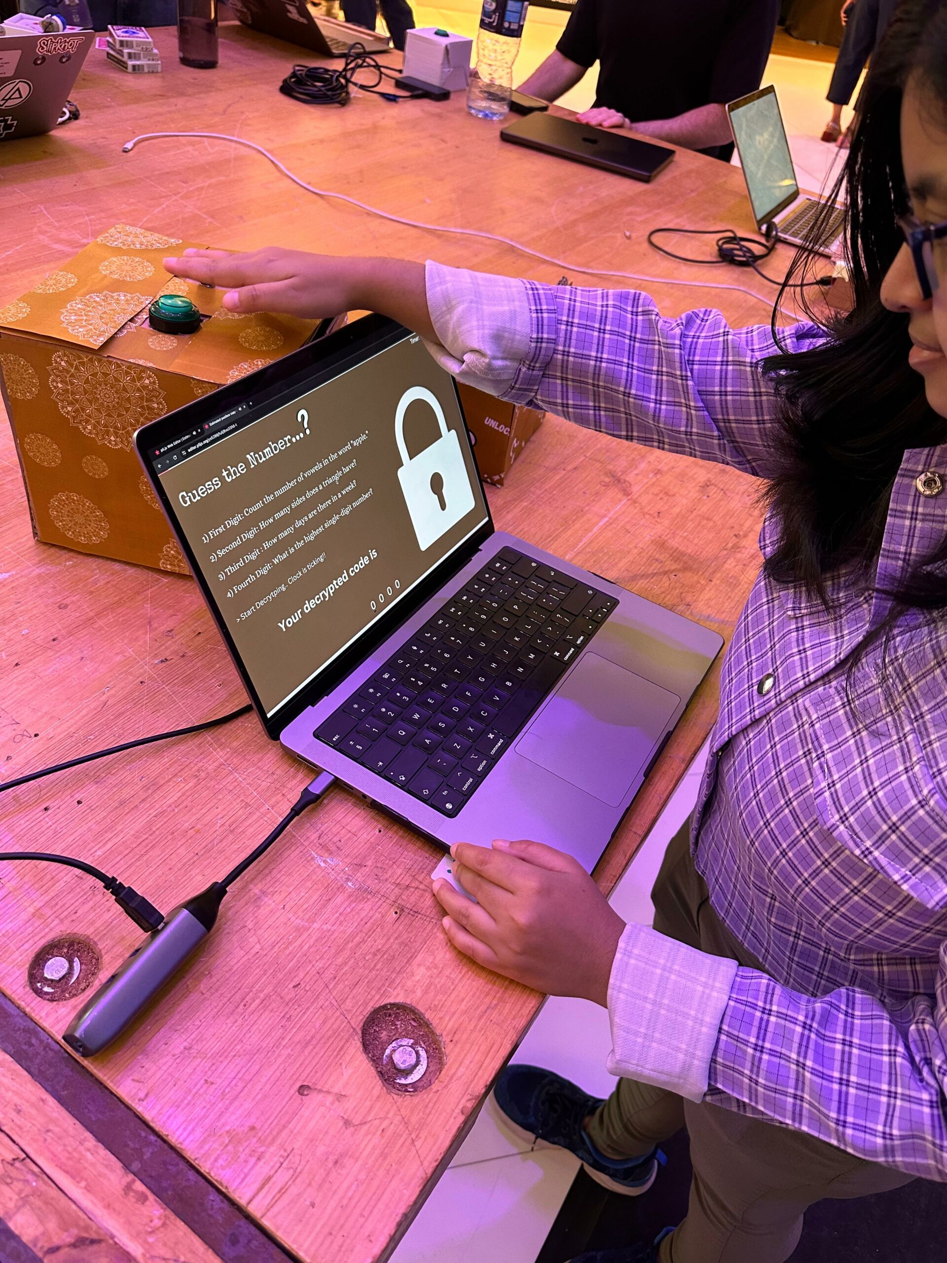
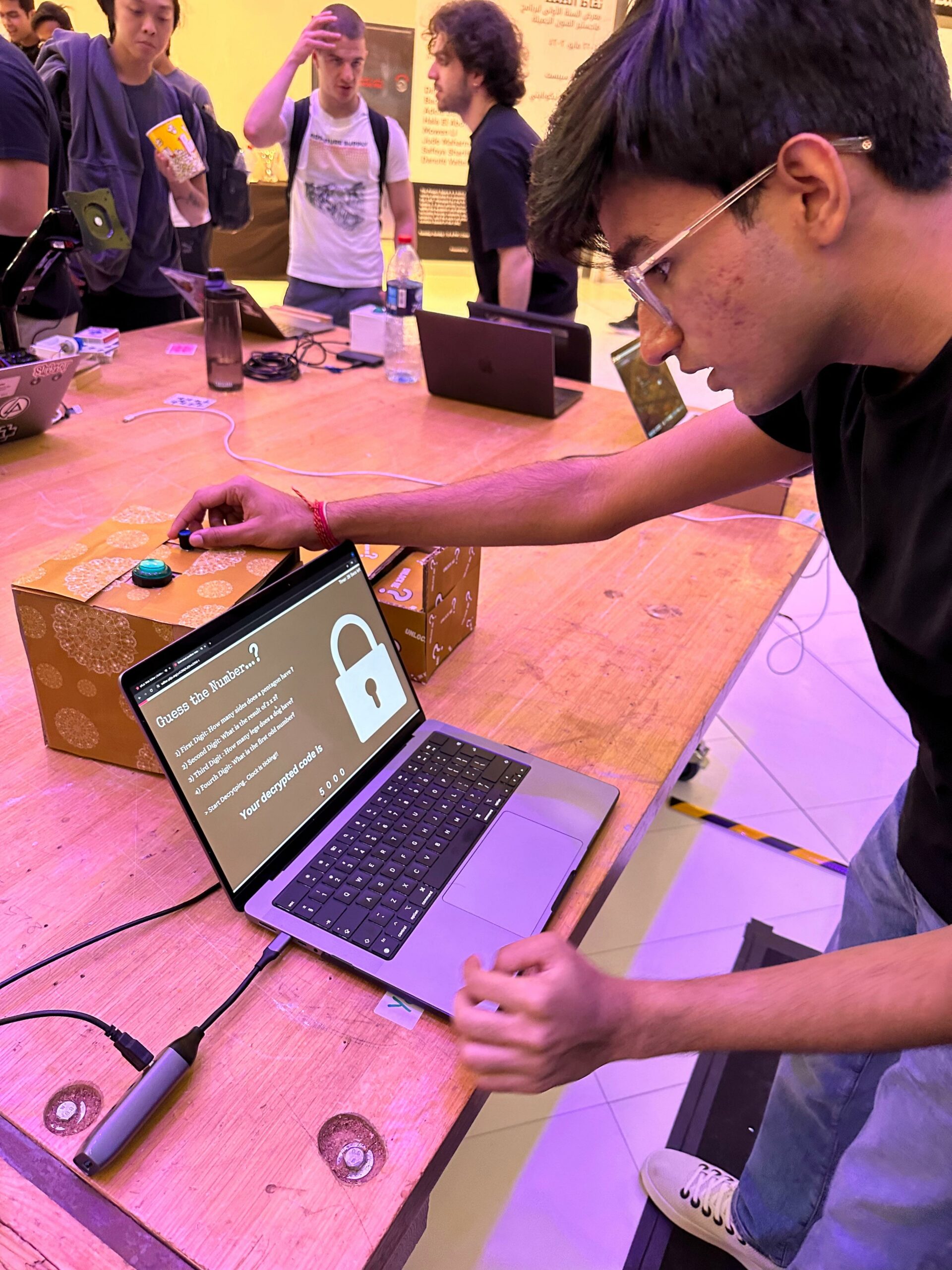
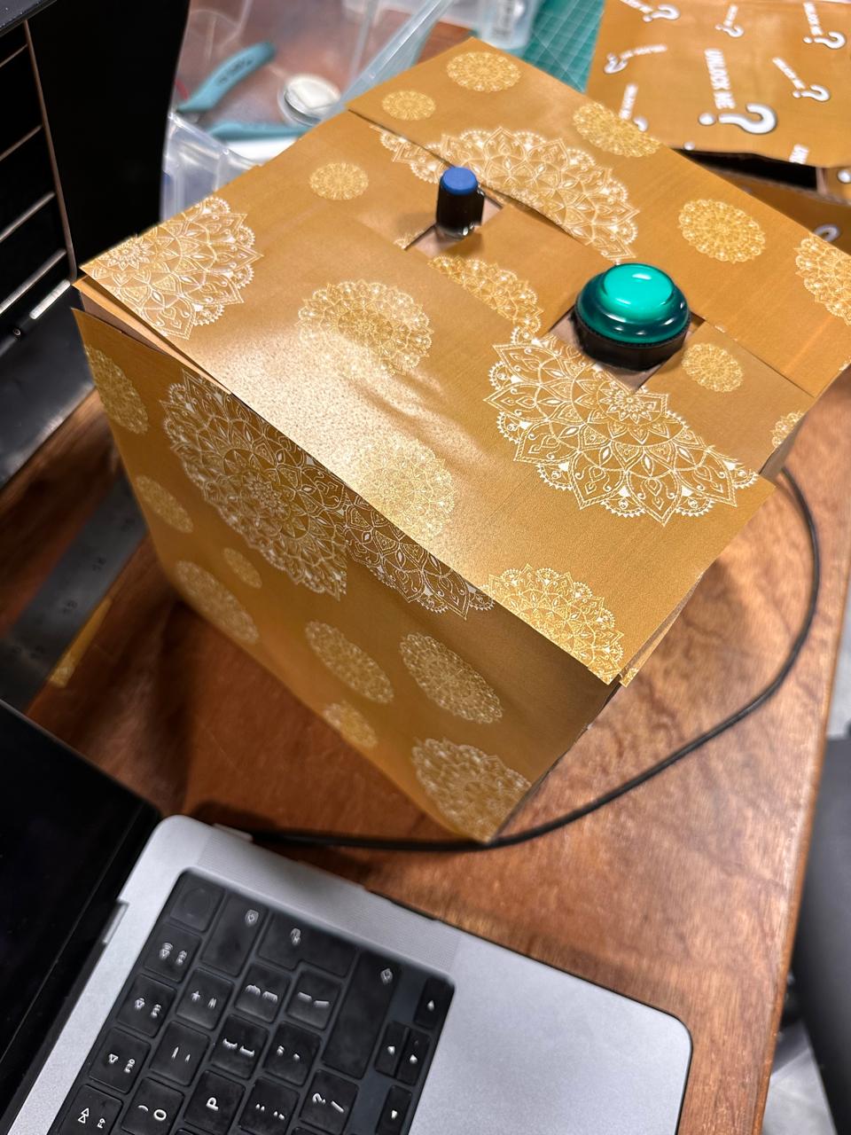 Image of the main user controller box.
User testing video:
1) Initial Testing: https://youtu.be/sKT85G0hJLI
2) Final Testing: https://youtu.be/hXSzTsB5x3o
Key Features:
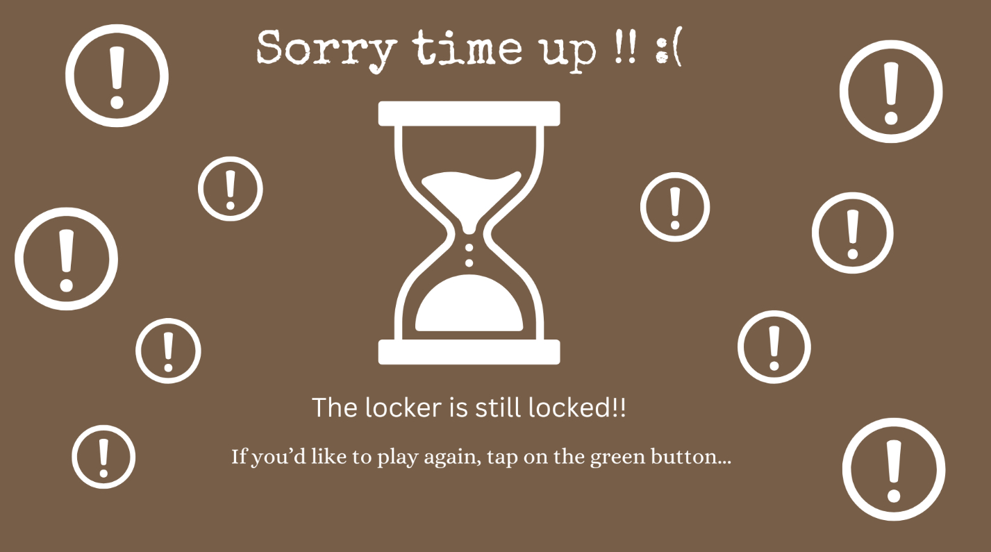
1) Dynamic Countdown Timer: A prominently displayed timer adds a sense of urgency and excitement to the gameplay. It counts down from a set time, pushing players to think and act quickly, which enhances the challenge and engagement of the puzzle.
2) Cryptic Hints Display: As players progress, cryptic hints are displayed on the screen to aid in decoding the puzzle. This feature helps to balance the difficulty level and ensures that the puzzle remains solvable while still challenging.
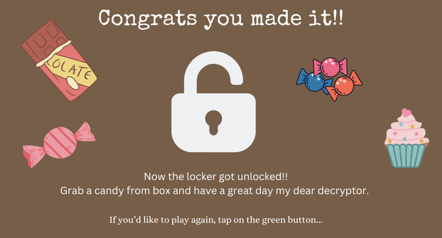
3) Feedback on Input Accuracy: When players enter a code, the interface immediately provides feedback. If the code is incorrect, players are prompted to try again, and if correct, a success message is displayed, and the box unlocks. This immediate feedback loop keeps players engaged and informed.
Components I used:
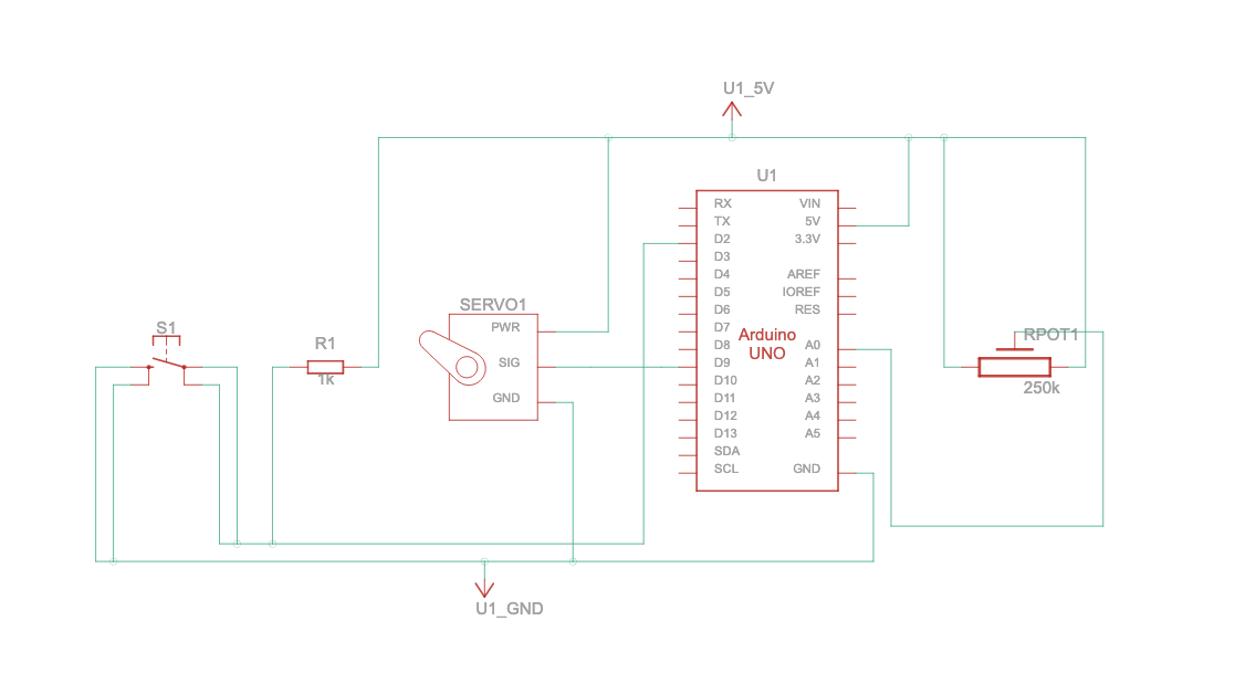
1) Arduino Uno: Serves as the main controller for input and output operations.
2) Servo Motor: Operates the locking mechanism of the box.
3) Potentiometer: Allows users to select digits for the code
4) Button: Used for entering selected digits and navigating through the game.
5) P5.js: It acts like a digital interface that provides instructions, feedback, and manages the timer and attempt counter.
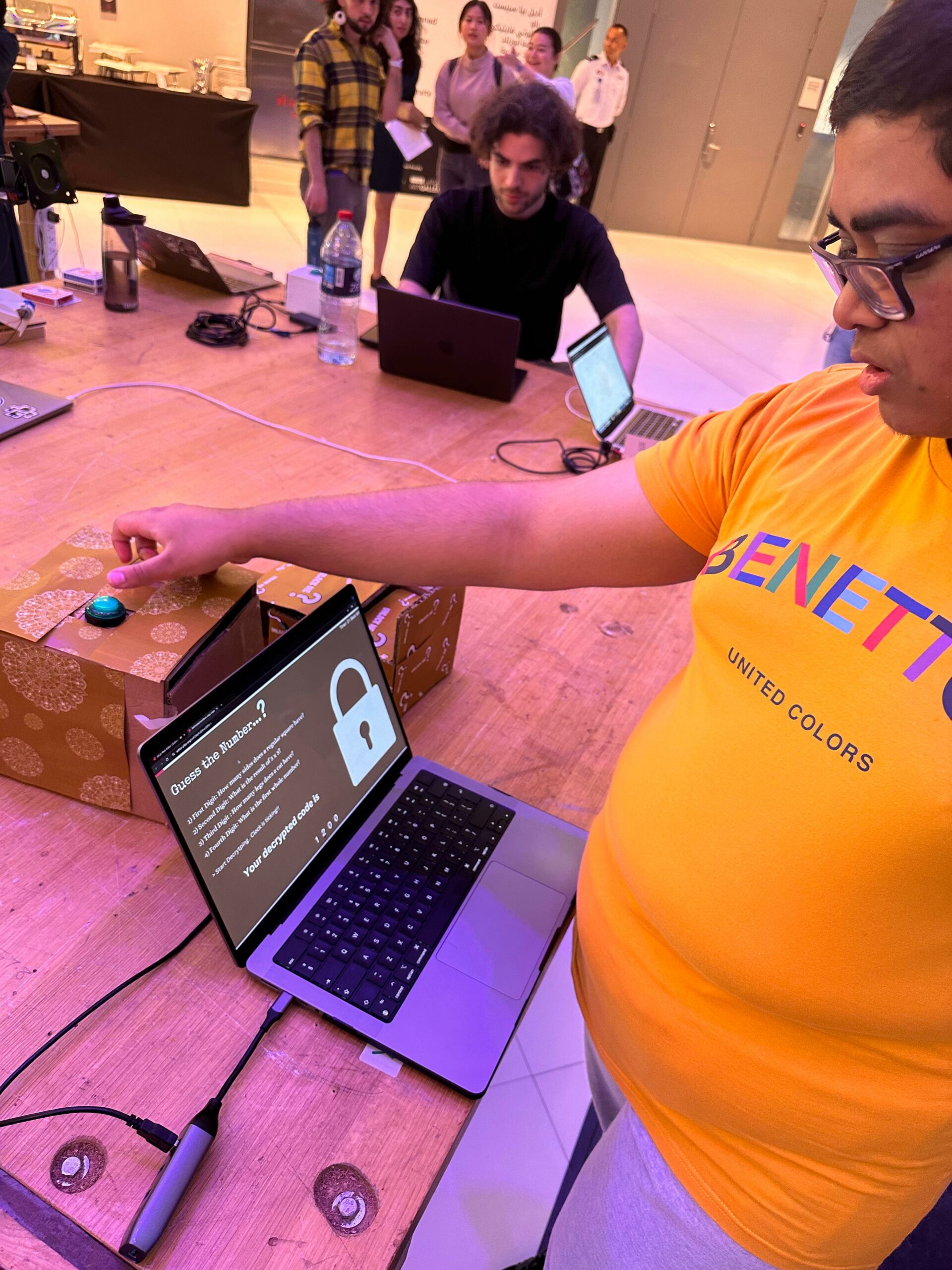
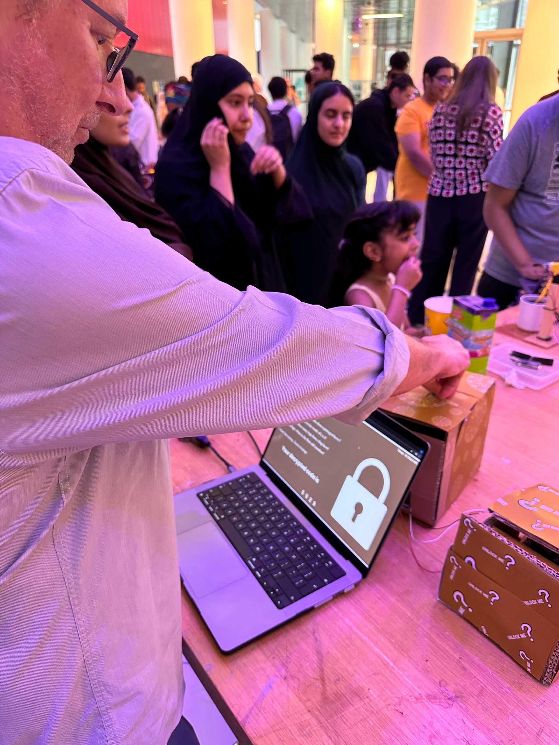
IM Show Pictures: People interacting with my project
Auto Locking Video: https://youtube.com/shorts/AAga9JHQt6c?feature=share
What’s the role of P5.js and Aurdino in this project?
P5.js Sketch: The P5.js sketch handles the game logic and user interface. It displays hints and the countdown timer.
Images:
Arduino Sketch: The Arduino controls the hardware aspects of the project. It uses a servo motor to lock and unlock the box. A potentiometer is used for dialing in digits (0-9), and a button confirms the entry of each digit. The Arduino sends these inputs to the P5.js program, which processes them to determine if the entered code matches the required one.
#include <Servo.h> // Include the Servo library

const int buttonPin = 2; // Push button connected to digital pin 2
int buttonState = 0;     // Variable to store the button state
const int potPin = A0;   // Potentiometer connected to analog pin A0
Servo servoMotor;        // Create a servo motor object

void setup() {
  pinMode(buttonPin, INPUT); // Set button pin as input
  Serial.begin(9600);        // Initialize serial communication
  servoMotor.attach(9);      // Attach the servo motor to digital pin 9
  servoMotor.write(0);       // Set initial position of the servo motor to 0 degrees
}

void loop() {
  buttonState = digitalRead(buttonPin); // Read the state of the button

  // If the button is pressed (buttonState is LOW)
  if (buttonState == LOW) {
    Serial.println("Button pressed!"); // Send message to serial monitor
    delay(1000); // Delay to debounce the button
  }

  // Read the value from the potentiometer and send it to the serial port
  int potValue = analogRead(potPin); // Read the value from the potentiometer
  int mappedValue = map(potValue, 0, 1023, 0, 10); // Map the value to the range 0-9
  Serial.println(mappedValue); // Send the mapped value to the serial port

  // Check if a signal is received from p5.js to control the servo motor
  while (Serial.available() > 0) {
    int signal = Serial.read(); // Read the signal from serial port
    if (signal == '0') { // Signal to reset servo motor to 0 degrees
      servoMotor.write(5); // Turn the servo motor to 0 degrees
    } else if (signal == '1') { // Signal to turn servo motor to 90 degrees
      servoMotor.write(90); // Turn the servo motor to 90 degrees
    }
  }

  delay(100); // Delay for stability
}
How the communication between P5.js and Aurdino Worked??
Initially I prepared the Arduino sketch to transmit data over the serial port. I wrote code to read sensor inputs, such as button presses or potentiometer values, and sent this data as messages over the serial port using functions like Serial.println() or Serial.write(). In my P5.js sketch, I initialized a serial port object within the setup() function using the new p5.SerialPort() constructor. This object represented the communication channel between my P5.js sketch and the Arduino connected to my computer.
Later I configured the serial port to listen for incoming data by using the serial.on('data', serialEvent) function. This setup ensured that whenever data was received on the serial port, the serialEvent function was automatically called, allowing my P5.js sketch to react to data sent from the Arduino. Within the serialEvent function of my P5.js sketch, I read incoming data from the serial port using the serial.readLine() function. This function retrieved a line of text sent from the Arduino over the serial port. I then processed this data based on its content, performing actions such as updating the display or triggering events in my P5.js sketch.
Additionally, I enabled bidirectional communication by allowing my P5.js sketch to send data back to the Arduino. This allowed me to control actuators connected to the Arduino, such as servo motors or LEDs, from my P5.js sketch. I used the serial.write() function to send data from my P5.js sketch to the Arduino and vice-versa, facilitating interactive control over hardware components.
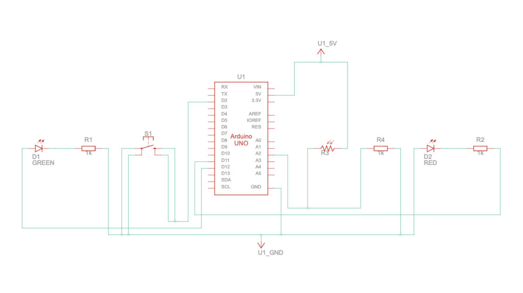
Schematics of the complete circuit:
 How the initial game works:

Challenges and Code I’m Particularly Proud of:
Among various aspects of my project, there’s one particular area that stands out – the locking mechanism.
Initially, the locking mechanism was designed to activate when the user entered all the codes correctly within a specific time frame. Subsequently, P5.js was supposed to send a signal to Arduino instructing it to rotate the servo motor to 90 degrees. However, I encountered challenges in implementing this functionality. Despite extensive debugging efforts, I struggled to achieve the desired outcome. It took numerous tutorial videos and multiple attempts, but eventually, I successfully resolved the issue.
// Check if the final number matches the correct code
  if (finalNumber === currentNumCode) {
    currentImage = congratsImg; // Display 'congrats.png'
    // Stop all other sounds and play win
    stopAllSounds();
    winSound.play();
    // Send signal to turn servo motor to 90 degrees
    serial.write('1');
  } else {
    currentImage = wrongImg; // Display 'wrong.png'
    // Stop all other sounds and play error
    stopAllSounds();
    errorSound.play();
  }

  // Reset values for the next round
  dashValues = [0, 0, 0, 0];
  currentDashIndex = 0;
  allowNumberSelection = false;
  clearInterval(timerInterval); // Stop the timer
}
Following the adjustment, I found that relying solely on correct numerical input wasn’t effective. Instead, I implemented a solution where upon displaying the “congrats.png” image in P5.js, the servo motor rotates 90 degrees, indicated by the code serial.write('1');. Conversely, if the “congrats.png” image is not displayed, the servo motor remains at 0 degrees, signified by serial.write('0');.
function serialEvent() {
  let message = serial.readLine(); // Read the incoming serial data

  if (message.includes("Button pressed!")) {
    // Toggle between images based on currentImage
    if (currentImage === welcomeImg) {
      serial.write('0');
      currentImage = instImg;
      // Stop all other sounds and play bgm
      stopAllSounds();
      bgmSound.play();
      // Reset the dashes to 0 when returning to welcomeImg
      dashValues = [0, 0, 0, 0];
      currentDashIndex = 0;
      allowNumberSelection = false;
      // Send signal to reset servo motor to 0 degrees

    } else if (currentImage === instImg) {
      allowNumberSelection = true; // Allow number selection
After successfully implementing this functionality, I extended its use beyond just locking mechanisms. I ensured that the system would automatically lock after the user restarted the game, enhancing the overall user experience.
Future Improvements and Comments from Users:
1. As initially planned in the game development, I would like to introduce a concept of levels. This will give players a strong sense of achievement as they complete each level. This is what one of my friend suggested after playing the game after multiple times.
2. To enhance this project even more, I aim to create a compelling story that will engage players deeply in the crypto game and enhance their overall gaming experience. In addition I would also like to add the SFX, for the number selection and opening the box.
3. Finally, I plan to add more locks (servo motors) to the candy box to make it more challenging to open. This will further motivate players to experience the thrill of unlocking the box.

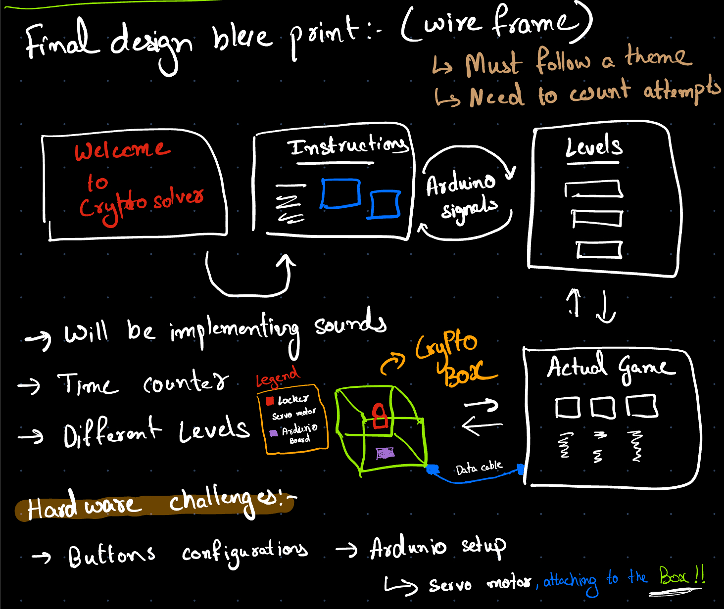
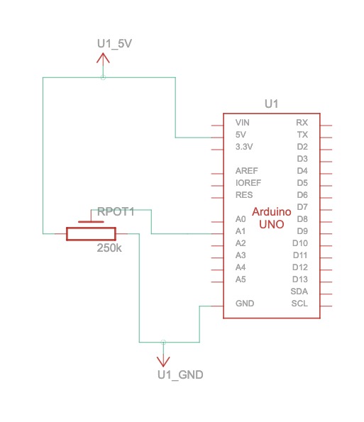
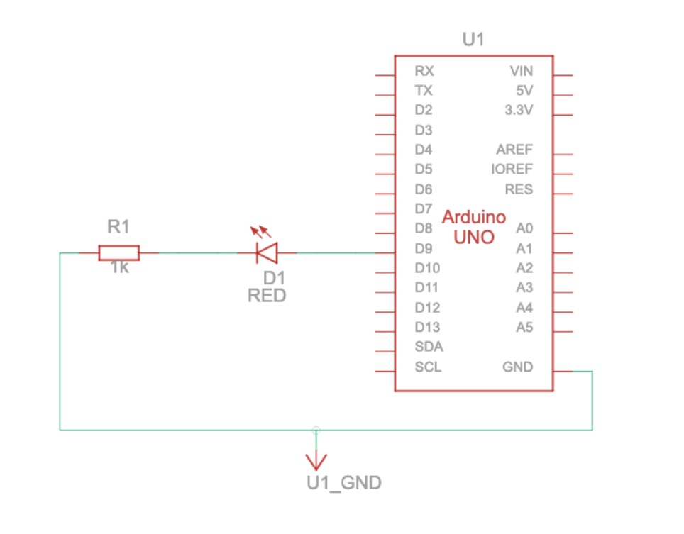
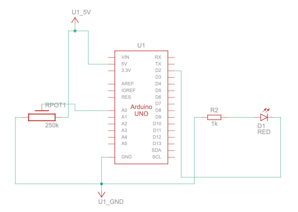
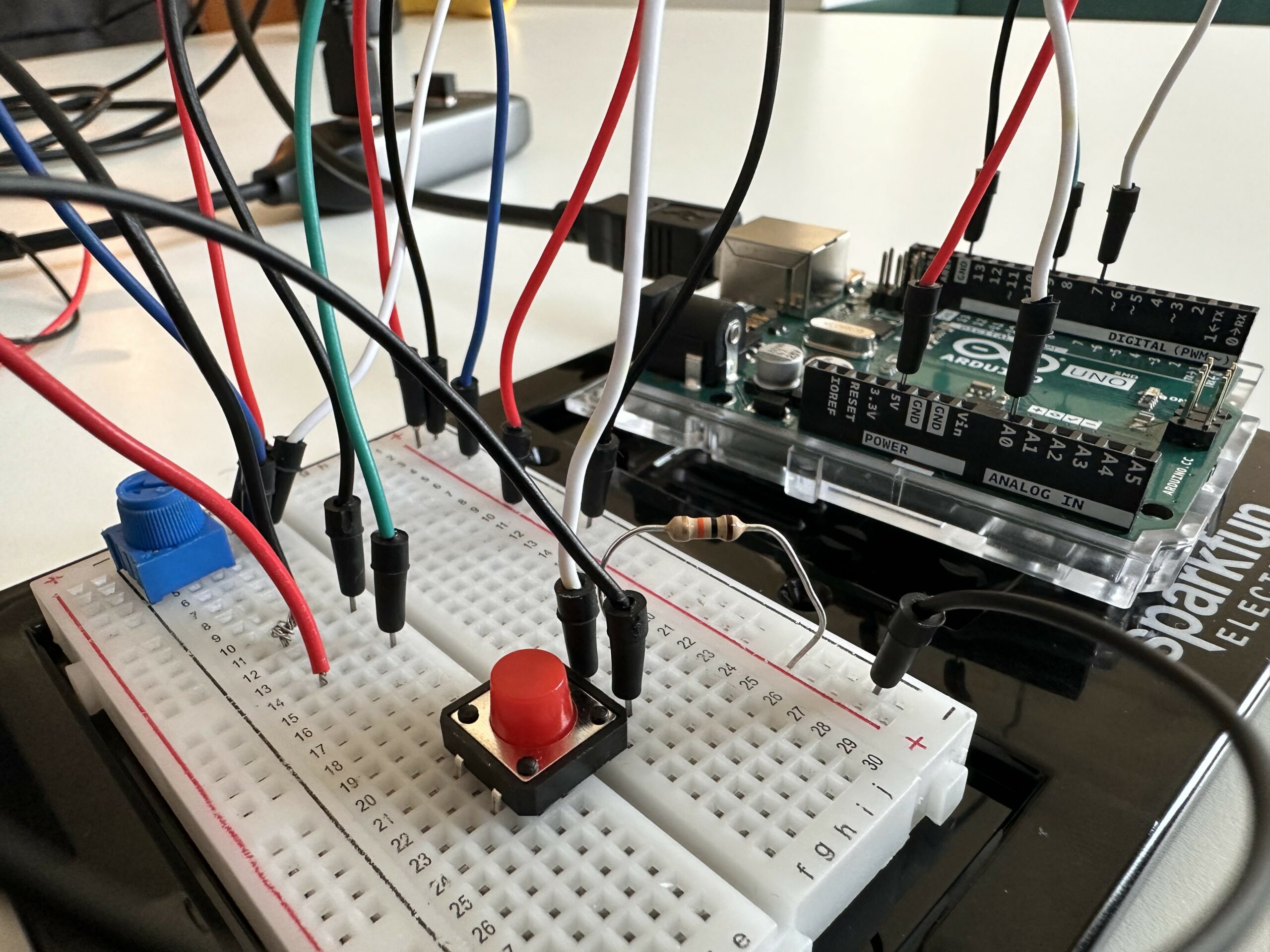
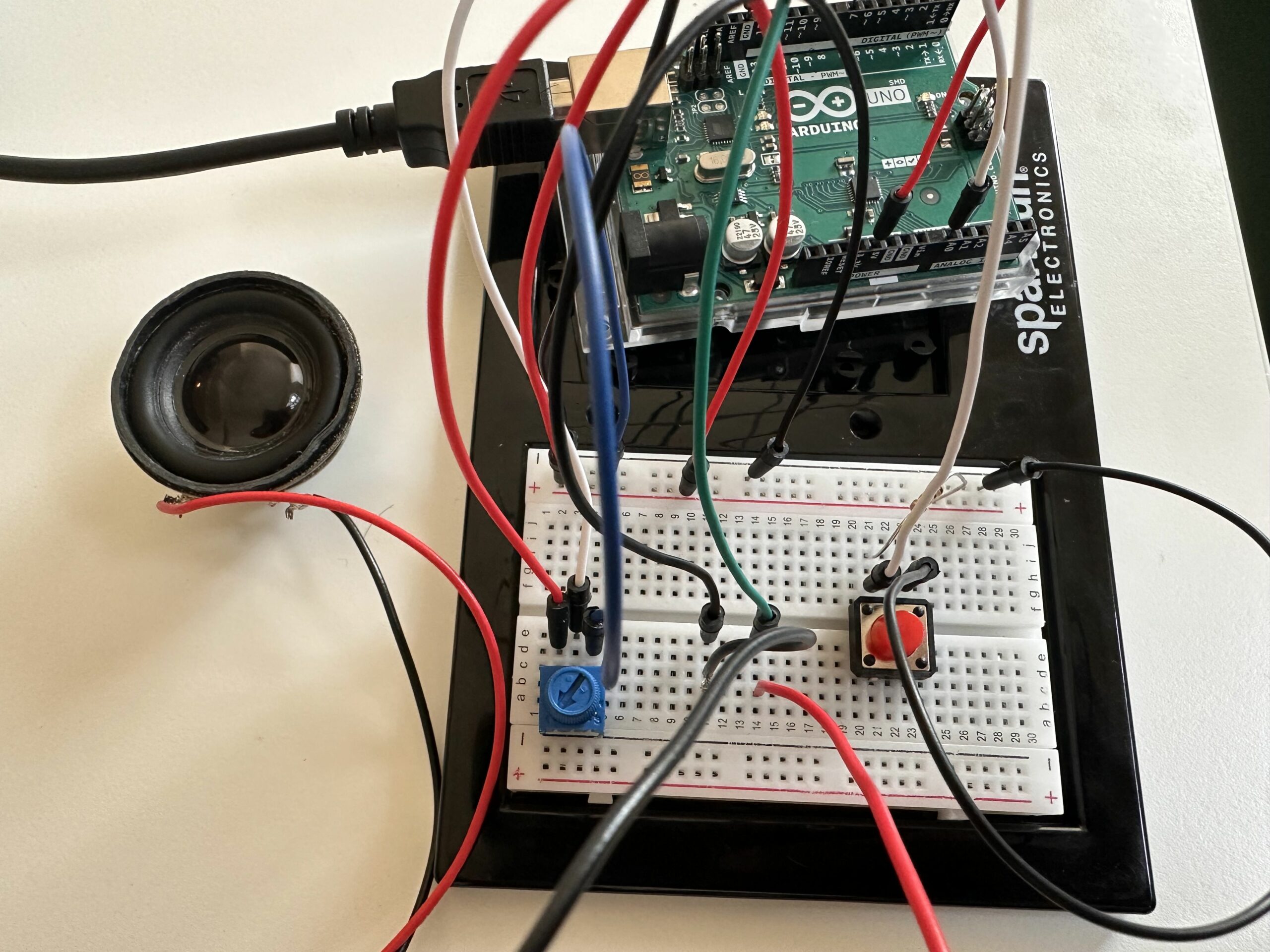
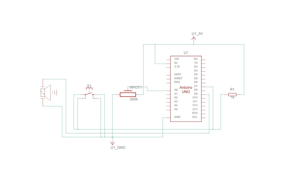
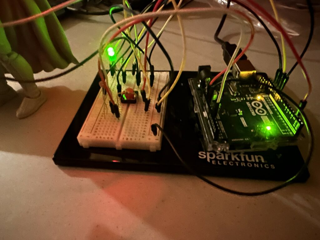 Figure 1.1: Closer View of the Circuit during Night time
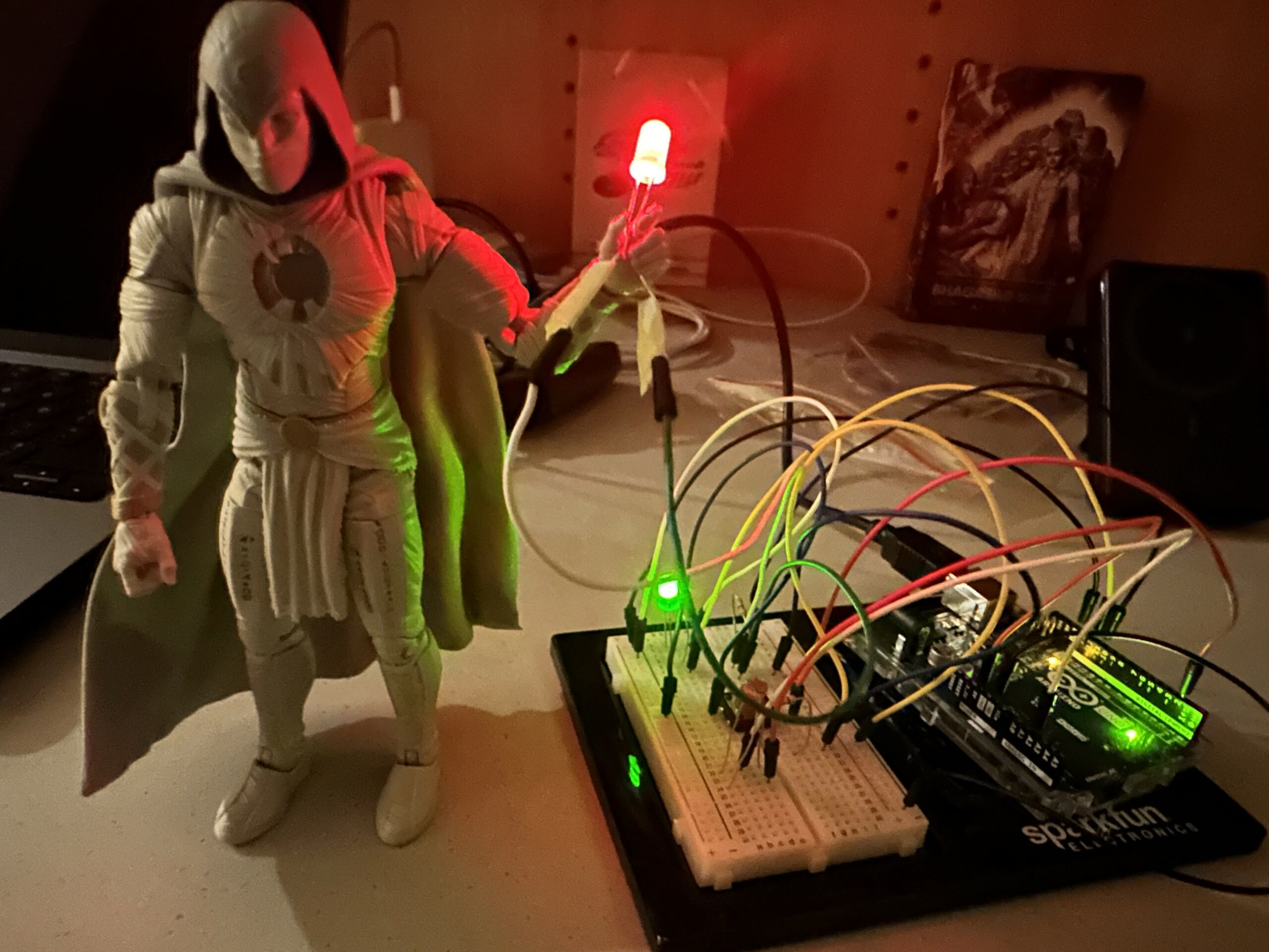
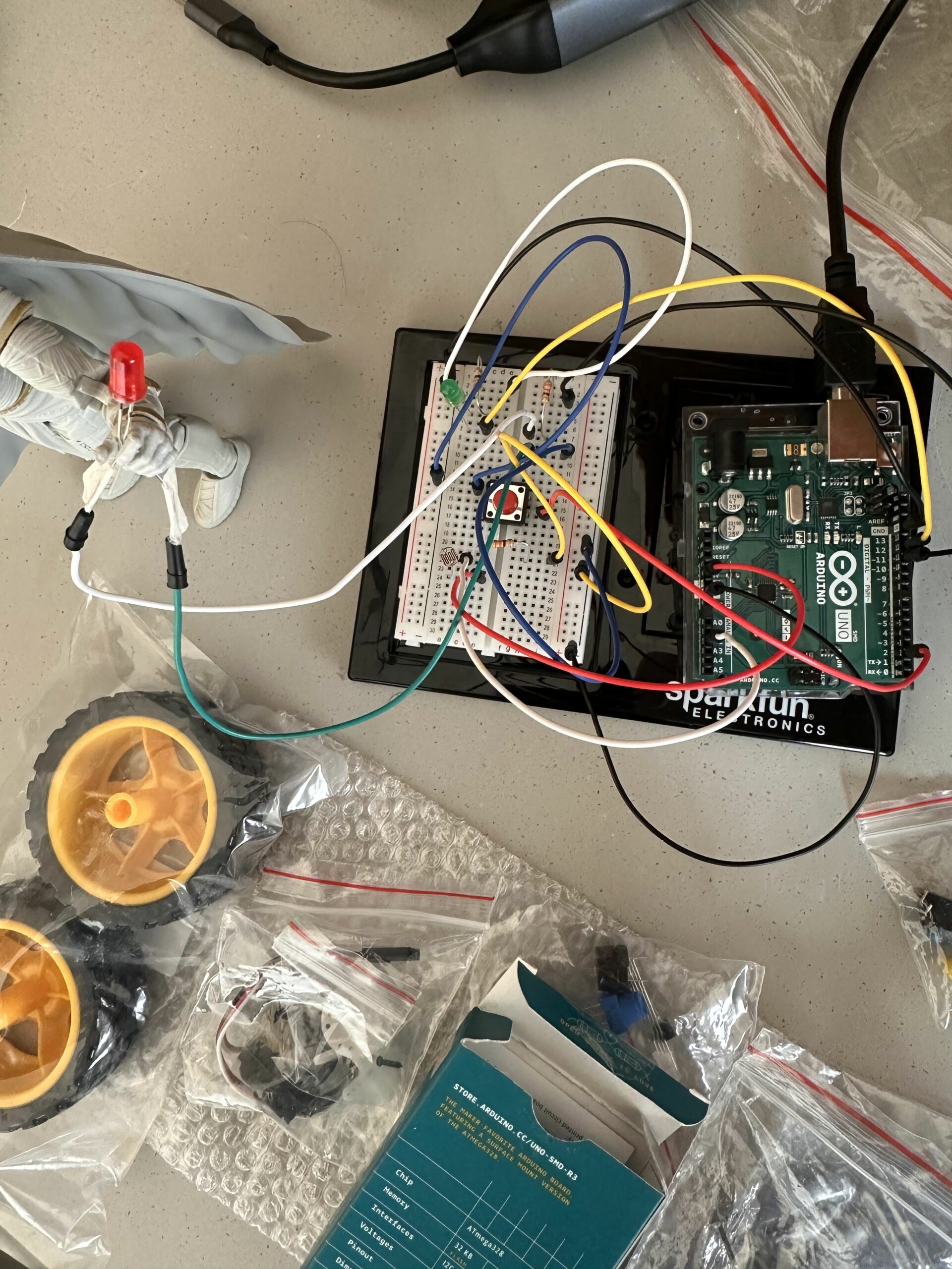

 How circuit works: