Final project Neuro_Jump

Concept:
Neuro-jump is an interactive game that aims to challenge its users and encourage them to think about using their body as an interaction tool that allows them to interact with technology. Neuro-jump detects the user’s EMG-muscle signals and allows them to control the jumping Alien cowboy by flexing their bicep muscle
This game is a critique to the status quo of video games and technology in general and an invitation to steer away from using the basic interactive tools such us touch screens and hand held items, and to think about the possibility of employing different techniques.

User testing:
Throughout the process of developing the game I have tried different settings and techniques. I have noticed that some people do very well whereas others struggle to play it. After multiple tests I figured out the best level of difficulty that is not too challenging but not too boring at this same time. I also implemented a slider that allows the users to change the height of the jump of the alien thus making the game easier.

Implementation:
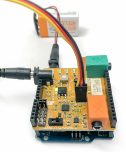
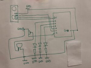
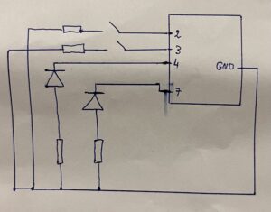
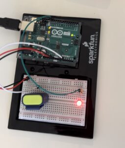
I have used P5 and Arduino to link the EMG signal detecting electrodes with the P5 side of the game. Setting the serial connection was not a very big challenge for me as I made sure only the necessary data will be ent form the Arduino to the computer which will make the user interaction instant and very fast and effective. I have also used the brain-shield gadget that allowed me to detect the EMG signal and transition them into digital data.
The game allows the user to both jump the incoming obstacles by flexing their hand but to also shoot the harmful birds by pressing the space Bar.
For the Arduino code I have used the original script that came with the hardware but I had to change and alter it to make it send the strength signal and use it in the length.

Future improvements and reflections:
I would like to implement the strength of the flex in the game and maybe make the jump or the attack depend on the strength of the flex. I would also like to add other tools that would allow the game to be played by two players instead of one, and maybe add another character and make the game a competitive. I would also like to create a “button-free” game the users can manipulate without the use of their hands but just their movement, facial expression or body position. I want to experiment mare with Interactivity and allow the users to be creative and have a fun time without the need of buttons or touch screens. For Neuro-Jump I would like to implement a program that detects facial gesture or body tracking that would allow the user the control the character.

P5:

Arduino code:

/*
* --------------------------------------------------------------------------------------
* Code monitors amplitude of EMG envelope, displays EMG strength on LED bar and controls
* robotic gripper by controlling servo motor.
* --------------------------------------------------------------------------------------
*/

#include <Servo.h>
#define GRIPPER_STATE_BUTTON_PIN 4          //pin for button that switches defult state
                                            //of the gripper (opened/closed)
#define SERVO_PIN 2                         //pin for servo motor
#define SENSITIVITY_BUTTON_PIN 7            //pin for button that selects sesitivity
#define NUM_LED 6                           //number of LEDs in LED bar
#define GRIPPER_MINIMUM_STEP 5              //5 degree dead zone (used to avoid
                                            //aiming oscilation)
#define OPEN_MODE 1                         //default gripper state is opened
#define CLOSED_MODE 2                       //default gripper state is closed
#define MINIMUM_SERVO_UPDATE_TIME 100       //update servo position every 100ms
#define Max_EMG_LED 3


Servo Gripper;                              //servo for gripper
byte ledPins[] = {8, 9, 10, 11, 12, 13};    //pins for LEDs in LED bar

//EMG saturation values (when EMG reaches this value
//the gripper will be fully opened/closed)
int sensitivities[] = {200, 350, 520, 680, 840, 1000};
int lastSensitivitiesIndex = 2;             //set initial sensitivity index

int emgSaturationValue = 0;                 //selected sensitivity/EMG saturation value
int analogReadings;                         //measured value for EMG
byte ledbarHeight = 0;                      //temporary variable for led bar height

unsigned long oldTime = 0;                  //timestamp of last servo angle update (ms)
int oldDegrees = 0;                         //old value of angle for servo
int newDegree;                              //new value of angle for servo

unsigned long debouncerTimer = 0;           //timer for button debouncer
int gripperStateButtonValue = 0;            //variable that stores state of button
int userReleasedButton = 1;                 //flag that is used to avoid multiple
                                            //button events when user holds button

int currentFunctionality = OPEN_MODE;       //current default position of claw


//-----------------------------------------------------------------------------------
//   Setup servo, inputs and outputs
// ----------------------------------------------------------------------------------
void setup(){

  Serial.begin(9600);
    //init servo
    Gripper.attach(SERVO_PIN);

    //init button pins to input
    pinMode(GRIPPER_STATE_BUTTON_PIN, INPUT);
    pinMode(SENSITIVITY_BUTTON_PIN, INPUT);

    //initialize all LED pins to output
    for(int i = 0; i < NUM_LED; i++){
        pinMode(ledPins[i], OUTPUT);
    }

    //get current sensitivity
    emgSaturationValue = sensitivities[lastSensitivitiesIndex];
}


//-----------------------------------------------------------------------------------
//   Main loop
//
//   - Checks state of sesitivity button
//   - Checks state of default-gripper-state button
//   - Measure EMG
//   - Shows EMG strength on LED bar
//   - Sets angle of servo based on EMG strength and current mode (open/closed)
// ----------------------------------------------------------------------------------
void loop()
{

    //-----------------------  Switch sensitivity ------------------------------------

    //check if button is pressed (HIGH)
    if (digitalRead(SENSITIVITY_BUTTON_PIN))
    {
        //turn off all the LEDs in LED bar
        for(int j = 0; j < NUM_LED; j++)
        {
            digitalWrite(ledPins[j], LOW);
        }

        //increment sensitivity index
        lastSensitivitiesIndex++;
        if(lastSensitivitiesIndex==NUM_LED)
        {
            lastSensitivitiesIndex = 0;
        }

        //get current sensitivity value
        emgSaturationValue = sensitivities[lastSensitivitiesIndex];

        //light up LED at lastSensitivitiesIndex position for visual feedback
        digitalWrite(ledPins[lastSensitivitiesIndex], HIGH);

        //wait user to release button
        while (digitalRead(SENSITIVITY_BUTTON_PIN))
        {
            delay(10);
        }
        //whait a bit more so that LED light feedback is always visible
        delay(100);
    }


    //----------------------------  Switch gripper default position open/close ---------

    //check if enough time has passed for button contact to settle down
    if((millis() - debouncerTimer) > 50)
    {
        gripperStateButtonValue = digitalRead(GRIPPER_STATE_BUTTON_PIN);
        //if button is pressed
        if(gripperStateButtonValue == HIGH)
        {
            //if last time we checked button was not pressed
            if(userReleasedButton)
            {
                debouncerTimer = millis();
                //block button events untill user releases it
                userReleasedButton = 0;

                //toggle operation mode
                if(currentFunctionality == OPEN_MODE)
                {
                    currentFunctionality = CLOSED_MODE;
                }
                else
                {
                    currentFunctionality = OPEN_MODE;
                }
            }
         }
         else
         {
            userReleasedButton = 1;
         }
    }


    //-----------------------------  Measure EMG ---------------------------------------

    analogReadings = analogRead(A0);//read EMG value from analog input A0


    //---------------------- Show EMG strength on LED ----------------------------------

    //turn OFF all LEDs on LED bar
    for(int j = 0; j < NUM_LED; j++)
    {
        digitalWrite(ledPins[j], LOW);
    }

    //calculate what LEDs should be turned ON on the LED bar
    analogReadings= constrain(analogReadings, 30, emgSaturationValue);
    ledbarHeight = map(analogReadings, 30, emgSaturationValue, 0, NUM_LED);

    //turn ON LEDs on the LED bar
    for(int k = 0; k < ledbarHeight; k++)
    {
        digitalWrite(ledPins[k], HIGH);
    }

  //-------------------- Send EMG strength data over serial -----------------------
  Serial.println(analogReadings);


    //-------------------- Drive Claw according to EMG strength -----------------------

    //set new angle if enough time passed
    if (millis() - oldTime > MINIMUM_SERVO_UPDATE_TIME)
    {
        //calculate new angle for servo
        if(currentFunctionality == OPEN_MODE)
        {
            analogReadings = constrain(analogReadings, 40, emgSaturationValue);
            newDegree = map(analogReadings, 40 ,emgSaturationValue, 190, 105);
        }
        else
        {
            analogReadings = constrain(analogReadings, 120, emgSaturationValue);
            newDegree = map(analogReadings, 120 ,emgSaturationValue, 105, 190);
        }

        //check if we are in servo dead zone
        if(abs(newDegree-oldDegrees) > GRIPPER_MINIMUM_STEP)
        {
             //set new servo angle
             Gripper.write(newDegree);
        }
        oldTime = millis();
        oldDegrees = newDegree;
    }
}


Final project proposal: Neuro-Jump

Background :                                                                                                                                      After we learnt about the future of design and having read the rant on the future of interaction design by bret vector. I started thinking deeper about the concept of interactivity and how we as the future generation of designers and technologists can design innovative and authentic interaction experiences that differ from the “glass screen”.

Solution:                                                                                                                                     Using a different interactive gadget that allows the user to immerse in a designed universe without using their fingers or hands!

Using electrodes would allow the detection of EMG signals of the muscle and that will make it possible to use “muscle flexes” as input that can be detected, transferred and used as main input in the final product..         Concept:                                                                                                                                     My idea is to create an interactive P5 video game that is based on a retro style game such as ( Racing games, Tetris or even flappy bird). I would like to use the Backyards brain product( Arduino+Shield+ Electrodes) and combine that with p5, where the video game/ virtual environment will be created. I might also develop another game that some how incorporate muscle flexes to commit some sort of action in the game/ virtual environment.

Arduino:                                                                                                                                            Other than the Arduino circuit, shield and the electrodes already provided. I would like to incorporate a buzzer and LEDs that will allow to add a visual and a sonic signals to the game making it more immersive and adding another layer to the game by including sound and light signals that depend on the either the strength or the length of the flex. The EMG detected signals will then be transferred by the Arduino to the p5 which will cause certain actions to happen in the game

P5:                                                                                                                                                        As I mentioned above the P5.js side of the project will probably be a game based on either a retro style game or another game that requires repetitive action such as flappy bird or bounce ball.

Issues:                                                                                                                                                   I would like to make the game very responsive so I need to check that the hardware and the P5.js game are both at tune so that the game does not lag when the EMG signal has not been detected.


Week 10: Arduino-P5 exercieces (Youssef-Arsalan)

Exercise 1: Make something that uses only one sensor on Arduino and makes the ellipse in p5 move on the horizontal axis, in the middle of the screen, and nothing on Arduino is controlled by p5.

P5 link:   https://editor.p5js.org/Arslan108/sketches/DVc3r1-YY            Arduino script:

// defines pins numbers
const int trigPin = 9;
const int echoPin = 10;
// const int ledPin = 3;
// int duty = 10;
// defines variables
long duration;
int distance;
void setup() {
  pinMode(trigPin, OUTPUT); // Sets the trigPin as an Output
  // pinMode(ledPin, OUTPUT); // Sets the trigPin as an Output
  pinMode(echoPin, INPUT); // Sets the echoPin as an Input
  Serial.begin(9600); // Starts the serial communication
}
void loop() {
  // Clears the trigPin
  digitalWrite(trigPin, LOW);
  delayMicroseconds(2);
  // Sets the trigPin on HIGH state for 10 micro seconds
  digitalWrite(trigPin, HIGH);
  delayMicroseconds(10);
  digitalWrite(trigPin, LOW);
  // Reads the echoPin, returns the sound wave travel time in microseconds
  
  duration = pulseIn(echoPin, HIGH);
  // Calculating the distance
  distance = duration * 0.034 / 2;
  // Prints the distance on the Serial Monitor * 0.034 / 2
  // analogWrite(ledPin, duty);
  Serial.println(distance);
  delay(150);
}

The Ball class defines the properties and methods for the ball, including its position, velocity, and radius. The update() method updates the ball’s horizontal position and velocity according to the gravity, bounce factor, and the sensor value that is taken from the ultrasonic distance sensor. The show() method is responsible for displaying the ball on the canvas.

Exercise2: Make something that controls the LED brightness from p5

P5 link: https://editor.p5js.org/Arslan108/sketches/rSn6NmdHy.                         Arduino script:

int ledPin = 3;


void setup() {
  pinMode(ledPin, OUTPUT);
  Serial.begin(9600);
  // put your setup code here, to run once:
  

}

void loop() {
  while (Serial.available()) {
    // digitalWrite(LED_BUILTIN, HIGH); // led on while receiving data

    int duty = Serial.parseInt();
    if (Serial.read() == '\n') {
      analogWrite(ledPin, duty);
    }
 

}
}

The code allows the control the intensity of the light emitted by the LED depending on the Y coordinate of the mouse. The higher the Y-coordinate is the brighter the LED is.

Exercise 3: Make something that controls the LED brightness from p5.

P5 link: https://editor.p5js.org/Arslan108/sketches/yhLl1hYsD.                                      Arduino script:

// defines pins numbers
const int trigPin = 9;
const int echoPin = 10;
const int ledPin = 4;
// int duty = 10;
// defines variables
long duration;
int distance;
void setup() {
  pinMode(trigPin, OUTPUT); // Sets the trigPin as an Output
  pinMode(ledPin, OUTPUT); // Sets the trigPin as an Output
  pinMode(echoPin, INPUT); // Sets the echoPin as an Input
  Serial.begin(9600); // Starts the serial communication
}
void loop() {
  // Clears the trigPin
  digitalWrite(trigPin, LOW);
  delayMicroseconds(2);
  // Sets the trigPin on HIGH state for 10 micro seconds
  digitalWrite(trigPin, HIGH);
  delayMicroseconds(10);
  digitalWrite(trigPin, LOW);
  // Reads the echoPin, returns the sound wave travel time in microseconds
  
  duration = pulseIn(echoPin, HIGH);
  // Calculating the distance
  distance = duration * 0.034 / 2;
  // Prints the distance on the Serial Monitor * 0.034 / 2
  int duty = Serial.parseInt();
    if (Serial.read() == '\n') {
      digitalWrite(ledPin, duty);
    }
  Serial.println(distance);
  delay(150);
  // digitalWrite(ledPin, low);
}

We have kept the code form exercise 1 but we have added the lines that send the light up order to the LED, every time the ellipse get in contact with the right or the left borders of the canvas.

let sendToArduino = light + "\n";
writeSerial(sendToArduino);
light = 0;


Surprise Birthday party- Music Machine

Music Machine:

The ultimate surprise party gadget. I have had this idea after my friend’s surprise birthday party. This gadget detects when the person passes in front of the ultrasonic motion sensor and automatically plays the famous birthday song tune and lights up three LEDs that create the festive vibes. The music machine also played a different tune depending on where the detected person (or teddy bear) is situated. Thus, the gadget will play different tune depending on the where the person is. This allows the music machine to keep playing different melodies throughout the party and set the party mood.

circuit :

the circuit includes ultrasonic motion sensor, buzzer, 3 LEDs, 3 resistors, variable resistor, Arduino uno.

I have included the variable resistor as it allows to adjust the volume of the buzzer. The LEDs are wired in parallel as it allow to for the LEDs to light up alternatively and create a light pattern. The diagram below describes all the wiring in the circuit:

Arduino script:

The biggest challenge I found while setting the script was making the LEDs light up simultaneously as the buzzer is on, but also creating some sort of pattern when the LED light up. I ended up solving that problem by creating a function Playtune() that gets called from inside the void Loop(). This allows both tasks to be done with interfering with each other.

int trig = 10;
int echo = 11;
long duration;
long distance;

// Define the LED pins
int led1 = 6;
int led2 = 7;
int led3 = 8;

// Define the Happy Birthday tune
int tune1[] = {264, 264, 297, 264, 352, 330};
int tune2[] = {264, 264, 297, 264, 396, 352};
int Newtune[] = {392, 330, 330, 349, 392, 392, 392, 440, 392, 349, 330, 294};


int tune1Length = sizeof(tune1) / sizeof(tune1[0]);
int tune2Length = sizeof(tune2) / sizeof(tune2[0]);
int NewtuneLength = sizeof(jaws) / sizeof(Newtune[0]);

void lightUpLed(int led, int duration) {
  digitalWrite(led, HIGH);
  delay(duration);
  digitalWrite(led, LOW);
}

void playTune(int tune[], int tuneLength) {
  for (int i = 0; i < tuneLength; i++) {
    tone(12, tune[i]);
    
    // Light up the LEDs in a rhythmic pattern
    lightUpLed(led1, 150);
    lightUpLed(led2, 150);
    lightUpLed(led3, 150);

    noTone(12);
    delay(50);
  }
}

void setup() {
  pinMode(echo, INPUT);
  pinMode(trig, OUTPUT);
  pinMode(led1, OUTPUT);
  pinMode(led2, OUTPUT);
  pinMode(led3, OUTPUT);
  Serial.begin(9600);
}

void loop() {
  digitalWrite(trig, LOW);
  delayMicroseconds(2);
  digitalWrite(trig, HIGH);
  delayMicroseconds(10);
  digitalWrite(trig, LOW);
  duration = pulseIn(echo, HIGH);
  distance = (duration / 2) * .0344;    // 344 m/s = speed of sound. We're converting into cm

  if (distance > 0 && distance <= 35) {
    if (distance <= 15) {
      playTune(tune1, tune1Length);
      playTune(tune2, tune2Length);
    } 
    else {
       playTune(Newtune, NewtuneLength);
    }
  }
}


Week-9 : WOOP-WOOP! the cops are here

Concept:                                                                                                                                     For this project I wanted to create the flashing lights of police cars. Using the two buttons the user can either turn on the red LED or the blue one. While when both buttons are pressed both LEDs starting flashing rapidly creating the same visual effect as a police car or an ambulance.

Equipment:                                                                                                                                       In this project I have used two red and blue LEDS, two push buttons, 4 resistors. Using the resistors is important not to just protect the LEDS but also they are necessary to protect the Arduino board and avoid creating a short circuit between the button, the pins 3 and 4 and ground.

Here is the design of the circuit:

ARDUINO SCRIPT:

const int ledPin1 = 7;
const int ledPin2 = 4;
const int buttonPin1 = 2;
const int buttonPin2 = 3;

const long rapidInterval = 100; // 100ms interval for rapid flashing

void setup() {
  pinMode(ledPin1, OUTPUT);
  pinMode(ledPin2, OUTPUT);
  pinMode(buttonPin1, INPUT_PULLUP);
  pinMode(buttonPin2, INPUT_PULLUP);
}

void loop() {
  byte buttonState1 = digitalRead(buttonPin1);
  byte buttonState2 = digitalRead(buttonPin2);

  if (buttonState1 == LOW && buttonState2 == LOW) {
    rapidFlash();
  } else {
    digitalWrite(ledPin1, buttonState1 == LOW ? HIGH : LOW);
    digitalWrite(ledPin2, buttonState2 == LOW ? HIGH : LOW);
  }
}

void rapidFlash() {
  digitalWrite(ledPin1, HIGH);
  digitalWrite(ledPin2, HIGH);
  delay(rapidInterval);
  digitalWrite(ledPin1, LOW);
  digitalWrite(ledPin2, LOW);
  delay(rapidInterval);
}


Unusual switch – Let there be light

For this assignment I have designed a circuit that turns on an LED when the surrounding environment is dark. The light detector serves as a switch that closes the circuit when light is not detected.

The light Dependent resistor LDR functions as a switch in this case. This component is very important as it allows to close the electrical circuit depending on the level of light in the surrounding environment. Such a circuit would be great to light up gardens and outdoor spaces at night automatically without having an actual human manually close the circuit.

Using an electrical component such as an LDR allows the user to save up on electricity for lighting. But it also comes with its drawbacks as sometimes the detector is not as accurate as we would like it to be but in many situations it does the job as in displayed in this project.

Midterm Game: Star Shooter

Inspiration:
The inspiration for Star Shooter comes from a variety of sources, including classic arcade games like Space Invaders and Galaga, as well as more modern games like Geometry Wars and Asteroids. These games typically involve shooting at large moving targets, often with a spaceship or other vehicle as the player’s avatar. The use of space-themed graphics, such as stars and comets, and the inclusion of a timer and score system are also one of the common features of shooting games. The game draws inspiration from science fiction movies and TV shows, which often depict space battles and laser gun fights.

Features and challenges:

One of the main features of the game is that it uses object-oriented programming to create dots and bullets that move around the screen. I had to use arrays to hold all of the dots and bullets, and I spent a lot of time making sure that the movement and collision detection was smooth and accurate, using efficient algorithms for collision detection. I used the testIntersection() function that allows the measurement of the distance between the radius of the bullet and the comet. If the distance is less than or equal to the sum of their radii, the bullet has intersected with the dot.

testIntersection(dot) {
  var d = dist(this.x, this.y, dot.x, dot.y);
  if (d <= this.r + dot.r) {
    return true;
  }
}

preload(): This function is used to load all the necessary assets (images) for the game before it starts. It is called once when the program starts. The arguments are the file paths to the image files that need to be loaded. The function works by using the loadImage() function provided by p5.js to load the images and store them in global variables for later use.

mousePressed(): This function is called once every time the left mouse button is pressed. It is used to create a new bullet object and add it to the bullets array. The function works by creating a new instance of the Bullet class and passing the current x-coordinate of the mouse as an argument. The new bullet is then added to the bullets array.

keyPressed(): This function is called once every time a key is pressed. It is used to create a new bullet object and add it to the bullets array when the spacebar key is pressed. The function works by checking if the key that was pressed is the spacebar key, and if it is, creating a new instance of the Bullet class and adding it to the bullets array.

Bullet.display(): This method is used to display the bullet on the canvas. It takes no arguments. The function works by drawing a rectangle on the canvas with a white fill color and a size of 10×20 pixels, using the bullet’s x- and y-coordinates.

Bullet.move() : This method is used to move the bullet up the screen. It takes no arguments. The function works by subtracting a fixed value from the bullet’s y-coordinate every frame, causing it to move up the screen.

Bullet.testIntersection(): This method is used to test if the bullet has intersected with a dot (enemy). It takes a single argument, which is a dot object to test against. The function works by calculating the distance between the center of the bullet and the center of the dot, and comparing it to the sum of their radii. If the distance is less than or equal to the sum of their radii, the bullet has intersected with the dot.

Dot.display(): This method is used to display the dot on the canvas. It takes no arguments. The function works by drawing an ellipse on the canvas with a red fill color and a size of 60×60 pixels, using the dot’s x- and y-coordinates.

Dot.move(): This method is used to move the dot around the canvas. It takes no arguments. The function works by adding a random value to the dot’s x- and y-coordinates every frame, causing it to move in a random direction. If the dot reaches the edge of the canvas, it is wrapped around to the opposite edge.

Assignment3: Creative Chaos


Inspiration:

For this project I was inspired by old TV static. Growing up I always wondered about the cause of old TV static. Through intro to Interactive media I was introduced to Perlin noise and the power of computers to produce random like graphics that seem to morph and change organically.

Concept:

In this project I attempted to recreate a noise-like graphic display that mimics a TV static but without using the NOISE() function. The piece displays moving black rectangles and switch to random colours once the the user clicks the mouse. The more frequent the clicks are, the more chaotic and static like design is.

Technicalities:

I used some of the code from the bouncing ball code from class. However, the trick was to remove the background which removes the clean cut aspect of the piece and allows the audience to see everything about the rectangles throughout time.


Week2: The alternating Wave

    Creating this art piece was a very fun and instructive process. I intended to create a simple and aesthetic piece that is also interactive and fun for the audience. I have used code that allowed me to create a sinus function in order to display an animated wave across the screen. The piece also displays two large circles with changing dimensions that move and morph depending on the coordinates of the mouse.

Both shapes; the circles and the sin wave, move accordingly as the frequency of the wave depends on the radius of the circles and change according to the y-coordinate of the mouse. I have used the code snippets below in order to create the morphing effects of the circles:

let x = mouseX;
let y = mouseY;
let ix = width – mouseX; // Inverse X
let iy = height – mouseY; // Inverse Y
fill(250, 150);
ellipse(x, height/2, y, y);
fill(0, 159);
ellipse(ix, height/2, iy, iy);

Using the variables ix and iy has been useful in creating the inverse and alternating visual effect in the piece, as many of the dimensions used depend on each other. This was a very helpful trick, since it allowed me to link the dimensions of different shapes and, thus making the piece more symmetric, cohesive and aesthetic.

One of the biggest challenges I faced while creating the piece was probably designing the sin wave as I was thinking of having multiple small ones on the screen. But the best decisions turned out to have only one big shifting wave as that takes the centre of the piece.

Youssef’s self portrait

Self portrait project using P5.js. I made this image using different shapes and images. I also managed to add text to it, in order to add the ‘NYU’ on the shirt. It was very interesting working on this project, as it actually allowed me to understand the P5 grid system and how to create and locate different shapes on the canvas. The main challenge I faced was drawing the hair as I had to change the coordinates of each circle in order to create the curly hair effect. I believe that there is probably better way to draw the hair maybe using bezier curves, or different shapes that would give a more realistic look. I however, find this design using circles more fitting in this case as it goes well with the style of the face of the rest of the face.

I am happy about how the torso turned out with the design of the NYU Logo. I also attempted to add an actual picture in the background to create a whole University student vibe with the portrait.

One of the issues I faced was probably overlaying different shapes on the canvas, especially with the neck and the NYU logo. However, I found out the order of the code affects the layer of the shape on the canvas.

One challenge I solved was the code for the Logo. In the beginning, I was thinking I had to create it using different shapes. But, I found out that with this chunk of code I can facilitate the whole issue:

//NYU
textAlign(CENTER, CENTER);
textSize(50);
fill(255);
text(“NYU”, 250, 460);