Mood Ring

What My Project Does:

For this project I used an RGB light and the temperature sensor to create a simplified version of a mood ring. When the user touches the temperature sensor, the sensor detects a certain temperature that correlates with an output RGB color that could be associated with someone’s mood. The red indicates that person is very warm, possibly happy, and energetic. Green indicate the person is stable, under normal conditions. Blue, finally, indicates the person is cold from air conditioning, or is just feeling bitter that day.

How I Did It:

I read up the Arduino site figure out how to get the temperature sensor to spit out a number that correlated with temperature. When I was able to find the code online on how to get an output number from the sensor, I found specific ranges to use when determining when the specific color would turn on.

The red color turns on when the output voltage reads above 0.80. The green turns on between 0.78 and 0.80. Finally, anything below 0.78 is blue. These are all correlated to temperatures between 24° and 26° Celsius.

For the temperature coding, essentially I used a code that would take a floated number retrieved from the A0 pinhole, and then that number, when multiplied by 0.004882814 (as I found online), produces the voltage number. Within my loop function, I assigned the variable ‘voltage’ to the voltage number received by the sensor. This number then, when subtracted from 0.5 and multiplied by 100 (again, as I found online), was the equivalent to degrees Celsius. I then had the voltage and degrees C° printed in order to find the ranges for the lighting and to make sure the sensor was outputting stable numbers. At one point, the sensor I was using overheated and started outputting the temperature as -25°, so when I changed it out for another sensor it worked fine.

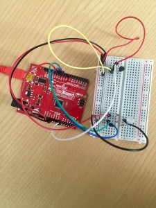
That’s a brief explanation of how the coding works. Below is the code with a few bits of commentary on what the coding means, followed by a video and set-up photo.

const int temperaturePin = 0;
int red = 11; //these correspond to the RGB pinholes
int green = 10;
int blue = 9;
void setup(){
  Serial.begin(9600); //For the sensor, this is the initial baud rate needed to match the speed of the code I'm running
  pinMode(red,OUTPUT);
  pinMode(green,OUTPUT);
  pinMode(blue,OUTPUT);
 
}
void loop() {
  float voltage, degreesC;
  
  voltage = getVoltage(temperaturePin); //(see below for the function that retrieves the voltage

  degreesC = (voltage - 0.5) * 100.0; //conversion of voltage to degrees

  Serial.print("voltage: "); //printing the voltage and corresponding degrees C
  Serial.print(voltage);
  Serial.print("  deg C: ");
  Serial.println(degreesC);
  delay(1000); 

  if(voltage > 0.80){ //for warmer temperatures, the light turns on as red
  digitalWrite(red,HIGH);
  } else {
    digitalWrite(red,LOW);
  }
  if(voltage > 0.78 && voltage < 0.80){ //for stable room temperature, the light turns on green
    digitalWrite(green,HIGH);
  } else {
    digitalWrite(green,LOW); 
  }
  if(voltage < 0.78){
    digitalWrite(blue,HIGH); //blue light for cooler temperatures
  } else {
    digitalWrite(blue,LOW);
  }
 
}

float getVoltage(int pin)   //This takes the A0 input and floats the number
{

 return (analogRead(pin) * 0.004882814); //the A0 number is multiplied by this to retrieve the voltage  
}


Setup of RedBoard:

12047560_1217202044962162_1230835908_n


Holiday Lights

For this project, I used yellow, red, and green lights that would turn on to their designated colored switches, and programmed them all to blink in a coordinated pattern with each other. Mostly, when making this project, I just kept thinking about Christmas. And while I couldn’t have snow or presents, I could at least program a tiny version of Christmas lights, while listening to carols during the project for a partial effect.

Apart from the finickiness of the switches and getting the wires to line up on the breadboard, the project was relatively easy to execute.

Initially, I tried to remember everything we learned from Wednesday’s class on programming and switches using photos I took from the class. Once I figured out how to turn on one yellow light with three switches, it became smooth sailing from there on what my errors were and how to fix them.

For this project, I used two red, two green, and two yellow lights, and the pairs were wired in parallel with each other so that they’d both turn on to the same switch input.

When you press the green button, the two green lights will light up at a specific pattern shown below in my coding. Likewise, when pressing the red button, the red lights would light up at a slightly faster speed, to light up whenever the green lights were off. And finally, when pressing the yellow button, the yellow lights will turn on when the other two lights are off. When pressing all three switches, the lights essentially light up in the sequence: green, then red, then yellow.

In order to make the lights work in parallel, the long ends are stuck in the same pin hole, and the short ends are put in the same row as 330 ohm resistors connected to ground. The switches are connected to the ground with a wire, and then a 10K ohmm resister in the row connected to the RedBoard.

When programming, I basically had three sections, with each switch connected to the designated color lights. Below is the chart I used to identify which switch went to which pin since it got confusing after a while with the wiring.

Switch in pin 3 turns on pin 7 green lights
Switch in pin 5 turns on pin 6 red lights
Switch in pin 4 turns on pin 2 yellow lights

Below is a video of how it works, and a copy of my coding:

CODING:

void setup() {
// put your setup code here, to run once:
//SWITCH Green
pinMode(3,INPUT);
// SWITCH Yellow
pinMode(4,INPUT);
// SWITCH Red
pinMode(5,INPUT);
//Red
pinMode(6,OUTPUT);
//Green
pinMode(7,OUTPUT);
//Yellow
pinMode(2,OUTPUT);

}
void loop() {
// put your main code here, to run repeatedly:

if(digitalRead(3) == HIGH){
digitalWrite(7,HIGH);
delay(250);
digitalWrite(7,LOW);
delay(750);
} else {
digitalWrite(7,LOW);

}

if(digitalRead(5) == HIGH){
digitalWrite(6, HIGH);
delay(100);
digitalWrite(6,LOW);
delay(500);
} else {
digitalWrite(6, LOW);
}

if(digitalRead(4) == HIGH){
digitalWrite(2,HIGH);
delay(50);
digitalWrite(2,LOW);
delay(250);
}else{
digitalWrite(2,LOW);
}
}

Project Dorothy

My setup is pretty basic: when I click my heels together, the light turns on.

I soldered the ends of two wires to two small pieces of conductible fabric. Those then are taped to the inside heels of my shoes. It worked on the first go, so this was a very smooth project. I am going to fiddle around to see what else I can do since this was fairly easy. Either way, here’s a video showing it work below. The overall circuit is completed on the breadboard, with two longer wires extended out from the power and resister and the light. Once the two wires connect, the switch closes the circuit. The conductible fabric was used in part to make the circuit easier to connect with more surface area, and also because I wanted to practice soldering (it was a messy job because the fabric melted as I was soldering (whoops)).

In Passing

The NYUAD campus is far big enough to where sometimes the campus feels rather empty. Only in specific meal times, like lunch in the Marketplace, really shows how many students live within the corners of the college. These clusters of individuals bunch together, leaving only a few students walking to and from class etc. Particularly when observing human interactions, I noticed the passersby talk. It’s a few brief comments with someone you’re acquainted with, but it simultaneously builds the relationship between the two people. If one person is worth recognition to the other in passing, this develops a growing bond. It’s either strengthened when the two meet up and spend more time together, or it dissipates into awkward eye contact.

Regardless, I further wondered in this interaction how a passersby communication between a person and a machine, perhaps when they’re on their way to class, will also harness a communication. Down to a basic ATM, this can become a daily habit of that person’s walk to use the ATM. Maybe even a screen showing what the weather is like outside. It’s brief, and in passing, but over time it becomes something one anticipates and looks for on their walk.

Small interactions build on themselves over time.