final.project – “ALIEN INVASION”

Concept

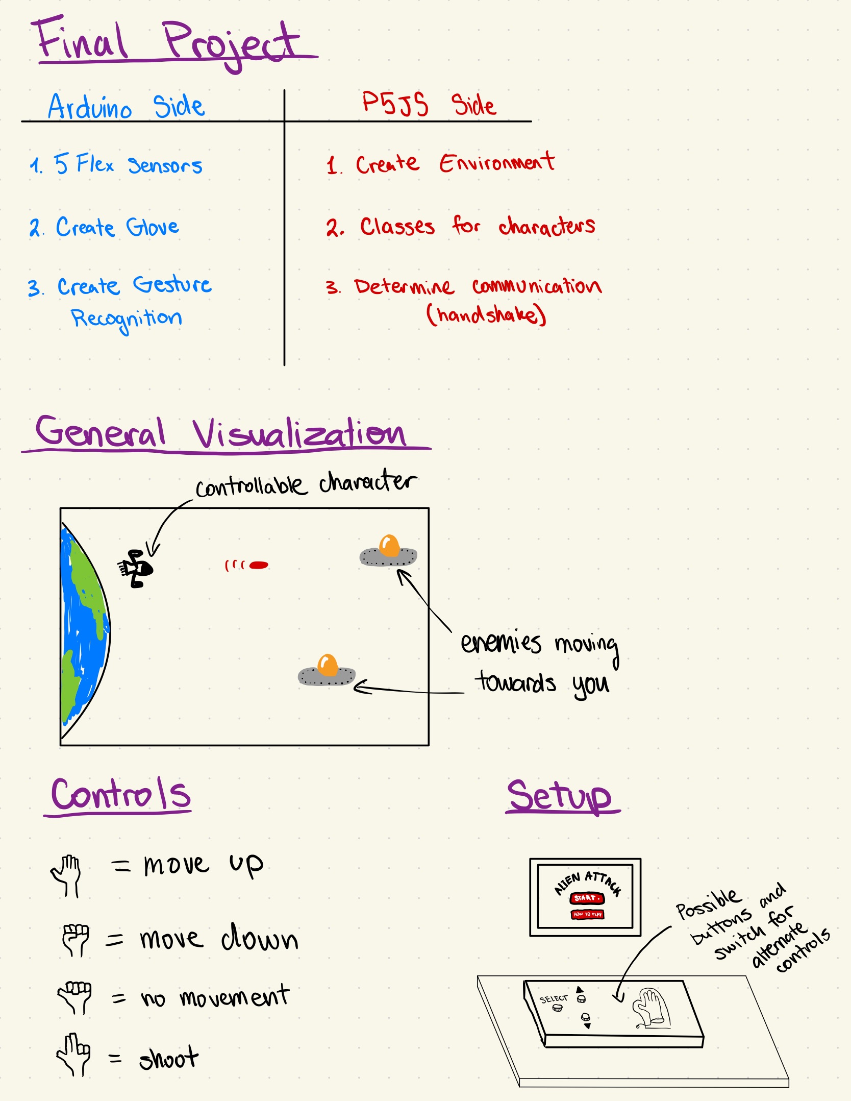
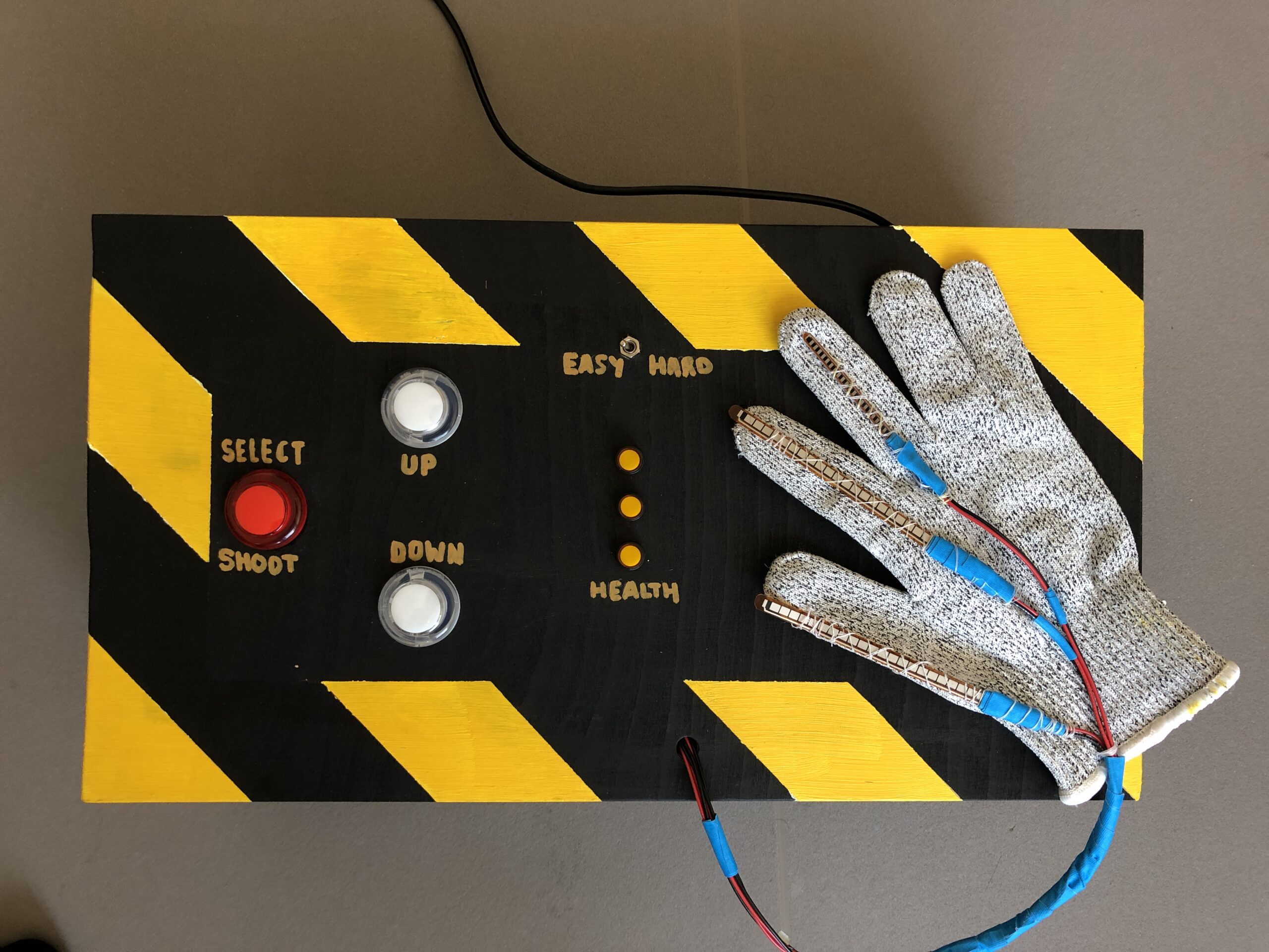
I decided to implement my idea of creating a unique controller for a video game, which in my case, was gesture control with a glove. I had decided to continue with the initial design; however, I decided to add an additional switch to change between simple button controls and using the glove to control the game. The game was a mash-up of Plants vs. Zombies and Space Invaders. I drew all the graphics for the game myself, and the game would be a high-score-based experience where each player can try to beat the previously set high score. Additionally, the enemies in the game spawn infinitely, and the difficulty increases with each wave of incoming enemies. The difficulty is dependent on the time that has passed since the start of the game and is measured by the speed at which the enemies come at you. Additionally, the game is fully controllable through the arcade-styled “controller box,” which has “SELECT, UP, DOWN” buttons and a toggle switch to change between “HARD” (glove controlling) and “EASY” (button control). Overall, I found the design quite intuitive, as did many others. Additionally, while working on the code, I added a feature to control the game through keyboard inputs, which can be activated by uncommenting the specified code segments.

User-Testing + Images & Videos

I had numerous friends try and use the project I have created, and the results were highly positive. The design was intuitive, and after just one or two tries, the testers got the hang of how the box and glove functioned. Overall, I think a big issue was that at the show, people did not spend much attention reading the instructions, which resulted in me having to restate what was written there verbally; in a more focused environment, I am sure this project would be very understandable and easy to use. It is, however, challenging to get used to controlling the player with the glove, and thus, it was called the HARD mode. Additionally, due to the issue of not being able to reuse the red button for switching between screens, I had to add some unique features for it to be better understood. In the instructions, I explicitly mention that you must first press the up and then start buttons, and after the game is over, the up and down buttons start blinking, indicating that you must press them together to restart the game. I will surely try to structure the code a bit differently whenever similar projects come up in the future.

Implementation

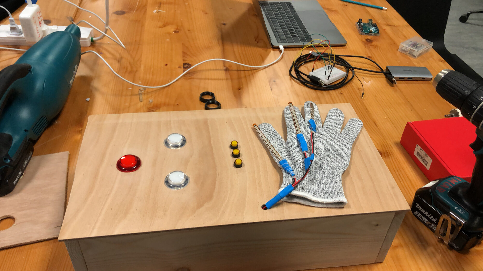
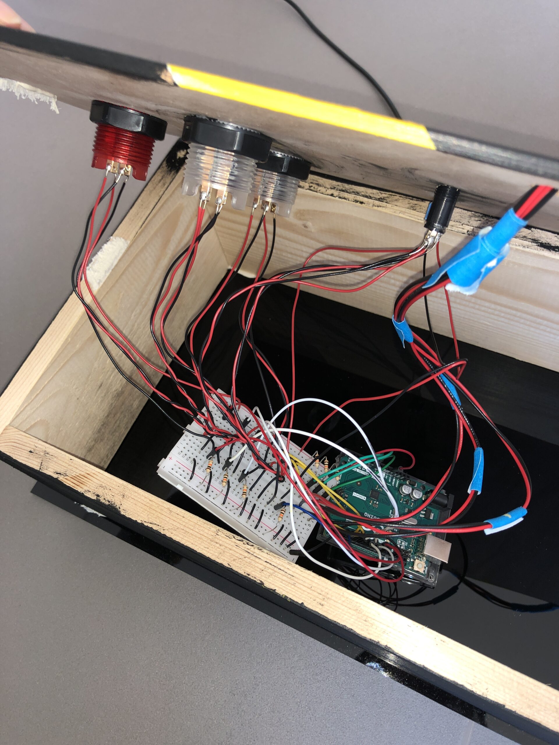
Interaction + Physical Design: My main intention with the design of this project was to make it reminiscent of the old-school arcade-style games, from the big light-up buttons, LEDs, and switches to the pixelated game characters and animations. I wanted to create a satisfying and nostalgic experience for the players of the game of a time when they had been to an arcade as a child. As I later found out, many people in the community here have not had these experiences before; therefore, it was also a new experience for them. However, the implementation of the glove provided a futuristic and high-tech twist to the old-school-styled project. This also interested many because who wouldn’t want to try playing a simple game with controls that are so different than what we are used to? Overall, I spent many hours designing, painting, and ensuring the physical structure of the box was well-thought-out and intuitive. A few images of the construction can be seen below.


Arduino

Surprisingly, the Arduino implementation of my project was much simpler than I had expected. The entire Arduino code is shown below:

//flex sensors and their respective fingers/input pins
int thumb = A2;
int index = A1;
int middle = A0;

//thersholds for the flex sensors
int bend = 800;
int thumb_bend = 730;


//inputs for digital switches
int mode_switch = 2; /// left side is 1 right is 0
int health_led1 = 3;
int health_led2 = 4;
int health_led3 = 5;
int white_switch1 = 6; 
int white_switch1_led = 7;
int white_switch2 = 8; 
int white_switch2_led = 9;
int red_switch = 10; 
int red_switch_led = 11;


//variables to send to p5
int move_up = 0;
int move_down = 0;
int shoot = 0;
int still = 0;
int mode = 0;
int white_up = 0;
int white_down = 0;
int red = 0;

// variable from p5
int health = 3;

void get_gesture() {
  int thumb_value = analogRead(thumb);
  int index_value = analogRead(index);
  int middle_value = analogRead(middle);
  if (thumb_value < thumb_bend && index_value > bend && middle_value > bend) { // condition for move up -- every finger bent except thumb
    move_up = 1;
    move_down = 0;
    shoot = 0;
    still = 0;
  } else if (thumb_value > thumb_bend && index_value > bend && middle_value > bend) { // condition for move down -- every finger bent
    move_up = 0;
    move_down = 1;
    shoot = 0;
    still = 0;
  } else if (thumb_value < thumb_bend && index_value < bend && middle_value > bend) { // condition for shooting -- only middle finger bent
    move_up = 0;
    move_down = 0;
    shoot = 1;
    still = 0;
  } else if (thumb_value < thumb_bend && index_value < bend && middle_value < bend) { // condition for no movement -- no fingers bent
    move_up = 0;
    move_down = 0;
    shoot = 0;
    still = 1;
  }
}

void get_switch_values() {  /// this function gets the buttons/switches values (1 or 0), to send to P5
  mode = digitalRead(mode_switch);
  white_up = digitalRead(white_switch1);
  white_down = digitalRead(white_switch2);
  red = digitalRead(red_switch);

  //make the leds with switches turn on with toggle and if pressed.
  if (mode == 1 && health != 0) {
    digitalWrite(white_switch1_led, HIGH);
    digitalWrite(white_switch2_led, HIGH);
    digitalWrite(red_switch_led, HIGH);
  } else if (mode == 0) {
    digitalWrite(white_switch1_led, LOW);
    digitalWrite(white_switch2_led, LOW);
    digitalWrite(red_switch_led, LOW);
    if (white_up == 1) {
      digitalWrite(white_switch1_led, HIGH);
    } else if (white_up == 0) {
      digitalWrite(white_switch1_led, LOW);
    }
    if (white_down == 1) {
      digitalWrite(white_switch2_led, HIGH);
    } else if (white_down == 0) {
      digitalWrite(white_switch2_led, LOW);
    }
    if (red == 1) {
      digitalWrite(red_switch_led, HIGH);
    } else if (red == 0) {
      digitalWrite(red_switch_led, LOW);
    }
  }
}
const long interval = 700;
unsigned long previousMillis = 0;
int ledState = LOW;

void show_health() {  // TURN ON LEDS DEPENDING ON HEALTH, BLINK UP AND DOWN BUTTONS IF DEAD
  if (health == 3) {
    digitalWrite(health_led1, HIGH);
    digitalWrite(health_led2, HIGH);
    digitalWrite(health_led3, HIGH);
  } else if (health == 2) {
    digitalWrite(health_led1, LOW);
    digitalWrite(health_led2, HIGH);
    digitalWrite(health_led3, HIGH);
  } else if (health == 1) {
    digitalWrite(health_led1, LOW);
    digitalWrite(health_led2, LOW);
    digitalWrite(health_led3, HIGH);
  } else if (health <= 0 && mode == 1 || mode == 0) {
    digitalWrite(health_led1, LOW);
    digitalWrite(health_led2, LOW);
    digitalWrite(health_led3, LOW);
    digitalWrite(red_switch_led, LOW);
    unsigned long currentMillis = millis();

    if (currentMillis - previousMillis >= interval) {
    // save the last time you blinked the LED
    previousMillis = currentMillis;

    // if the LED is off turn it on and vice-versa:
    if (ledState == LOW) {
      ledState = HIGH;
    } else {
      ledState = LOW;
    }

    // set the LED with the ledState of the variable:
    digitalWrite(white_switch1_led, ledState);
    digitalWrite(white_switch2_led, ledState);
  }
  }
}

void setup() {
  // Start serial communication so we can send data over the USB connection to our p5js sketch
  Serial.begin(9600);

  //defining the pins
  pinMode(LED_BUILTIN, OUTPUT);
  pinMode(health_led1, OUTPUT);
  pinMode(health_led2, OUTPUT);
  pinMode(health_led3, OUTPUT);
  pinMode(white_switch1, INPUT);
  pinMode(white_switch1_led, OUTPUT);
  pinMode(white_switch2, INPUT);
  pinMode(white_switch2_led, OUTPUT);
  pinMode(red_switch, INPUT);
  pinMode(red_switch_led, OUTPUT);
  pinMode(mode_switch, INPUT);

  //start the handshake
  while (Serial.available() <= 0) { // everything blinks while waiting for serial data from p5
    Serial.println("0"); // send a starting message
    digitalWrite(health_led1, HIGH);
    digitalWrite(health_led2, HIGH);
    digitalWrite(health_led3, HIGH);
    digitalWrite(white_switch1_led, HIGH);
    digitalWrite(white_switch2_led, HIGH);
    digitalWrite(red_switch_led, HIGH);
    delay(300);
    digitalWrite(health_led1, LOW);
    digitalWrite(health_led2, LOW);
    digitalWrite(health_led3, LOW);
    digitalWrite(white_switch1_led, LOW);
    digitalWrite(white_switch2_led, LOW);
    digitalWrite(red_switch_led, LOW);
    delay(300);
  }
}

void loop() {

  // wait for data from p5 before doing something
  while (Serial.available()) {
    digitalWrite(LED_BUILTIN, HIGH); // led on while receiving data
    health = Serial.parseInt();
    
    if (Serial.read() == '\n') {
        get_gesture();
        get_switch_values();
        show_health();
        delay(1);

        Serial.print(move_up);
        Serial.print(",");
        Serial.print(move_down);
        Serial.print(",");
        Serial.print(shoot);
        Serial.print(",");
        Serial.print(still);
        Serial.print(",");
        Serial.print(mode);
        Serial.print(",");
        Serial.print(white_up);
        Serial.print(",");
        Serial.print(white_down);
        Serial.print(",");
        Serial.print(red);
        Serial.println();
    }
  }
  digitalWrite(LED_BUILTIN, LOW);
}

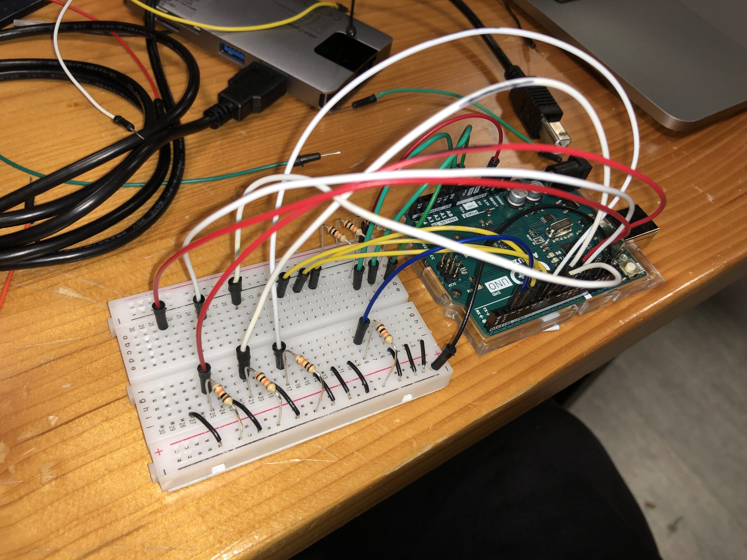
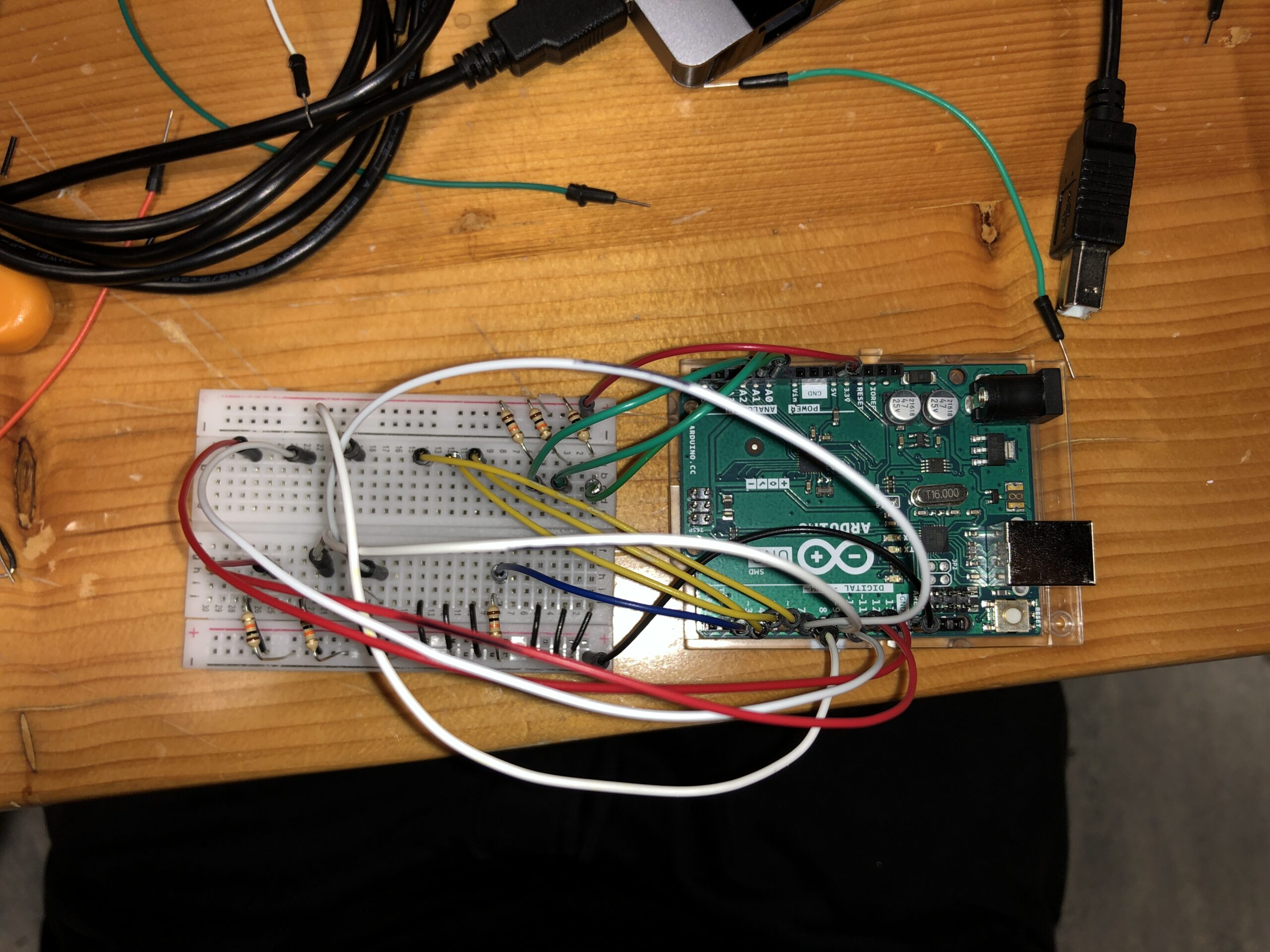
I decided to create functions for each of the actions needed for Arduino to keep the serial communication loop a lot cleaner. Additionally, the gestures are recognized within the Arduino, and then the according values for move_up, down, and so on are sent to P5. Additionally, the circuit design and connections can be seen below:

P5JS

The P5JS code is too long to post here and can be found by following the embedded sketch. The segment below is the one I struggled most with:

check_collision() {
  // check for collisions between bullets and enemies
  for (let b = this.bullets.length - 1; b >= 0; b--) {
    if (this.bullets[b].active) {
      for (let enemy = game.enemies.length - 1; enemy >= 0; enemy--) {
        if (game.enemies[enemy].alive) {
          let enemy_x = game.enemies[enemy].x;
          let enemy_y = game.enemies[enemy].y;
          let bullet_x = this.bullets[b].x;
          let bullet_y = this.bullets[b].y;

          if (dist(bullet_x, bullet_y, enemy_x, enemy_y) < 150) {
            // Bullet hits the enemy
            game.enemies[enemy].explode();
            this.score += 1;
            this.bullets[b].inactive();
          }
        }
      }
    }
  }

  // remove inactive bullets that go beyond the right edge
  this.bullets = this.bullets.filter(
    (bullet) => bullet.active && bullet.x < width
  );

  // check for collisions between enemies and the player
  for (let enemy = game.enemies.length - 1; enemy >= 0; enemy--) {
    if (game.enemies[enemy].alive) {
      let enemy_x = game.enemies[enemy].x;
      let enemy_y = game.enemies[enemy].y;
      let player_x = this.x;
      let player_y = this.y;
      let player_r = this.w / 2;
      let enemy_r = game.enemies[enemy].img_w / 2;

      if (!game.enemies[enemy].collided_with_player) {
        if (dist(player_x, player_y, enemy_x, enemy_y) < player_r + enemy_r) {
          // enemy hits the player
          game.enemies[enemy].explode();
          game.enemies[enemy].collided_with_player = true;
          this.health -= 1;
        }
      }

      // check for enemies reaching the left side of the screen
      if (enemy_x <= 0 && !game.enemies[enemy].collided_with_player) {
        game.enemies[enemy].explode();
        game.enemies[enemy].collided_with_player = true;
        this.health -= 1;
      }
    }
  }
  // remove exploded enemies
  game.enemies = game.enemies.filter((enemy) => enemy.alive);
}

In order to implement functional collision detection between the enemies, bullets, player, and “earth” (left side of the screen), I had to iterate through many lists and add many additional attributes to every class. This method is called in the game class when the game is played. I had to research a new way of removing elements from a list since I ran into MANY issues with the objects being deleted and then another loop trying to access their attributes. Therefore, I decided to look into the “.filter” method in JavaScript to remove certain objects AFTER the loops had finished. The resource I used is linked below. Apart from this, it was also challenging to manage the input of buttons since the Arduino would send 1s and 0s hundreds of times a second. This was resolved by adding a few flags and conditions, which can be found in one of the methods in the game class in the p5 sketch.

Communication – Arduino <-> P5JS

I found the communication between Arduino and P5JS to be very simple and understandable. From the Arduino, I sent 8 values to P5, which can be seen in the Arduino code. I then used these values (1s or 0s) in P5JS to control the character and everything else. Therefore the input from the mouse or keyboard was unnecessary, apart from initially connecting the Arduino to the serial port. P5 sends Arduino the health value of the player, which is then displayed by the LEDs on the mainframe of the box. Unfortunately, the LEDs I used were not as bright as I wanted them to be. However, the function worked well. Overall, I found the communication process quite intuitive and easy to understand.

Challenges & Reflection

Overall, I found this experience extremely enjoyable since I have never before had a chance to create something that is so advanced (at least for me as a starting interactive media and computer science student). However, there have been many challenges and long nights spent trying to figure out how to make things work. I faced my first challenge when constructing the glove and the enclosure. The flex sensors needed to be able to move and bend; therefore, I had to hand-sow each sensor to the glove instead of gluing them down, which took a lengthy amount of time. Additionally, once I had all the buttons, switches, and LEDs attached to the box, it was highly challenging to insert the wires into the breadboard since there was little space and everything was very tight-knit. Once the box had been constructed, even more challenges arose in P5. The code I had written previously was not working well. Specifically, the collision detection between the bullets and the enemies was not working. It took me over 5 hours of trying to debug the code and test various ways to fix the issue. However, yet again, another issue arose. As I was trying to use one button to change between the screens (states of the game), since the input of the button was read continuously, it was extremely difficult to try to find a way to use one button for different actions on different screens as the readings would be changed right as the state changed. I am sure there is a solution to this; however, as I was running out of time, I had to use an alternative and different buttons for switching between screens. Ultimately, despite the many challenges and difficulties that I have faced, I enjoyed the process and am particularly proud of making the game fully functional and using the glove as an input for controls. I am excited to pursue similar projects in the future. On a side note, I wish I had more time to implement some extra features to my project. For instance, I would have liked to add extra buttons for other features, such as power-ups or a separate restart/start button, and so on. The possibilities are wide, but I am content with my final result.


Sources

https://builtin.com/software-engineering-perspectives/javascript-filter

https://p5js.org/reference/

week12.assignment – Final Project Plan

Concept

Considering the time limitations, upon deep contemplation of my two pervious ideas, I decided to focus on creating a single game with a unique controller in the form of a glove. Below a brief plan for how the game interface will look, the setups, and what the controls will be is shown.


As of now, there are a few more things that I will most likely decide on as I will be constructing the final project very shortly. First of all, I will need to create the game in 5p and make sure it works with no input from the Arduino. Simultaneously, I will work on developing the controlling glove with the Arduino. One issue that I have noticed is that the flex sensors are not extremely accurate, and thus, I will have to benchmark every sensor and determine the specific value ranges that will work well for it (0-1023). I am still unsure if I would want to use the amount of flex to control the speed since that would complicate the process significantly. Therefore, I will most likely create certain conditions in the Arduino code that would send numerical values through the serial communication, which would respond to the different actions in the p5 sketch. Additionally, I will add a few LEDs to the physical controller board to indicate the health points remaining of the player. Another feature I would like to try to implement is allowing users to save their high scores.

Arduino Inputs/Outputs

The Arduino will collect measurements from 5 flex sensors and at least 3 digital inputs (buttons). The data from the flex sensors will be processed within the Arduino code. Consequently, this will determine if certain conditions are met and will send these values to p5.

The Arduino will receive data from p5, which will correspondingly light up LEDs for the remaining health (3 LEDs).

P5.JS Inputs/Outputs

The P5 sketch will receive the data from the Arduino and process it to the corresponding actions to be performed in the game. The P5 sketch will keep sending data about the health points remaining to the Arduino.

week11.reading – Design Meets Disability

In this chapter from Graham Pullin’s book Design Meets Disability, the author delves into the history, complications, applications, and interplay between designs and life-enhancing devices. I believe the main ideas that Pullin is trying to address are highly evident through the examples of eyewear. As mentioned, the concept of physical lenses was never initially intended to be a part of fashion nor to embrace the physical complications. Nevertheless, with time, glasses became a significant part of fashion, even though their main purpose was to enhance the vision and life of those who have physical limitations in regard to their eyesight. The chapter discusses numerous such instances where engineers and scientists develop systems without an idea of the physical design in mind, but society can gradually adapt and change these systems, integrating them seamlessly into our lives.

However, it is critical to comprehend that a balance must exist between design and functionality. Certainly, with devices such as hearing aids, one cannot focus fully on the best visual design and neglect the functionality of the product. Similarly, this ideology influences the progressive and innovative technologies that we see today. When creating such systems, individuals must also consider what are the societal, cultural, and other external influences that will either enhance or diminish the need or usefulness of the product. Ultimately, I believe that this reading has given me a new perspective on how design meets disability and how societies are able to remarkably influence the adaptation and usefulness of products that might have been designed with no intention of including a good visual design.

week11.assignment – Final Project Ideas

Concepts

When we first began working with the Arduino, I was excited about all the possibilities that arose for my final project. Additionally, I found working with Arduino quite intuitive and am hoping to implement unique features for the final project. As of now, there are two main ideas that I have in mind.

Idea 1 – Virtual Arcade with a Twist

My first idea for the final project revolves around creating a virtual arcade, using P5, and implementing the control for the minigames using analog and digital sensors with Arduino. The p5 sketch would present a virtual arcade with at least two or three different minigames that you would be able to select using a physical component, for instance, a button with an arrow right to highlight the object on the right or left and vice-versa. Once the player decides on what game they would like to play by pressing the select button (digital switch), the game screen would change to that of the selected minigame. As of now, I have two interesting and unique ideas for the minigames. The first is a game where a character has a jetpack and is stuck in a box. Randomly, different objects will be generated and move horizontally at different speeds. The character will be controlled by a sound level meter, and the louder the input of the player, the higher the character will float on the screen. Each object avoided is 1 point. After the player dies, the score will be saved as a high school and displayed for other players to try to beat. The next minigame idea I have is to create a Wack-a-Mole but with a twist. In this version of the game, there will be an array of digital switches and LEDs above them. However, every round, two of the buttons will light up, with different colors. This would make the game more challenging as the person would have to press the button with the correct color. If the player presses the button which has a different color, then a point is deducted from the score.

Idea 2 – Unique Controller

My first idea might take a lot of time to fully implement, and if that were the case, then my other idea would be to create just one game that would rely on the input of a unique control. This idea was inspired by the lack of innovation that I have noticed when it comes to gaming console controllers. Evidently, the current controllers are popular because they are ergonomic and intuitive. However, I believe that it would be interesting to explore and try to create a unique controller that relies on different inputs for controlling a game. One such unique controller could be a special glove that uses flex sensors to determine the bending of finders in a hand. A game that could go well with this would be a Plants vs. Zombies type of game, in which a character can be controlled to move on the vertical axis and could shoot projectiles to stop the incoming enemies from reaching the other side of the screen, which would result in a loss of health points. Additionally, the game would have waves of increasing difficulty, in which the enemies would move faster, and there would be more enemies in total. The hand controls for this game would involve bending your fingers into different positions, which would indicate movement and actions for the game.

Possible Challenges

For my first idea, I believe the main challenge would be time and physically constructing the different sensors and interfaces for the minigames. Even though I am confident this idea is possible to implement, I am not too confident about the amount of time that I have to make it happen. This makes me lean towards implementing my second idea. For the second idea, I believe the biggest challenges would be ensuring the accuracy of the flex sensors and creating a well-designed glove for the control of the game, as well as ensuring that the gesture recognition works well. As I am writing this, I have also realized that a glove-like controller, like the one I would like to make, could be used as a translator for sign language. This implementation, of course, would also require additional elements such as an accelerometer and extremely precise readings from the flex sensors; however, this could be a unique opportunity for a future project.

week11.assignment – Serial Communication

Exercise One – Ellipse Movement with Sensor

In this exercise, I decided to use the light sensor to control the horizontal position of the ellipse in the center of the screen by mapping the serial values of the light sensor to the y position of the ellipse.

let yShift = 0;
let alpha = 255;


function setup() {
  createCanvas(640, 480);
  textSize(18);
}

function draw() {
  
  background(205);
  
  ellipseMode(CENTER);
  ellipse(width / 2 , height/2 + map(yShift, 0, 1023, -255, 255), 50, 100);

  // the other value controls the text's transparency value
  fill(255, 0, 255, map(alpha, 0, 1023, 0, 255));

  if (!serialActive) {
    text("Press Space Bar to select Serial Port", 20, 30);
  } else {
    text("Connected", 20, 30);
    

    // Print the current values
    text('yShift = ' + str(yShift), 20, 50);
    text('alpha = ' + str(alpha), 20, 70);

  }

function keyPressed() {
  if (key == " ") {
    // important to have in order to start the serial connection!!
    setUpSerial();
  }
}

// This function will be called by the web-serial library
// with each new *line* of data. The serial library reads
// the data until the newline and then gives it to us through
// this callback function
function readSerial(data) {
  ////////////////////////////////////
  //READ FROM ARDUINO HERE
  ////////////////////////////////////

  if (data != null) {
    // make sure there is actually a message
    // split the message
    let fromArduino = split(trim(data), ",");
    // if the right length, then proceed
    if (fromArduino.length == 2) {
      // only store values here
      // do everything with those values in the main draw loop
      
      // We take the string we get from Arduino and explicitly
      // convert it to a number by using int()
      // e.g. "103" becomes 103
      yShift = int(fromArduino[0]);
      alpha = int(fromArduino[1]);
    }

    //////////////////////////////////
    //SEND TO ARDUINO HERE (handshake)
    //////////////////////////////////
    let sendToArduino = "0,0" + "\n"; 
    // we dont need arduino to recieve anything so we can send empty         
    // information
    writeSerial(sendToArduino);
  }
}


Exercise Two – LED Brightness Control from Arduino

Yet again, I decided to repurpose the previous code and modify it so that now P5 would send data to the Arduino, but it doesn’t need any data from Arduino.

function setup() {
  createCanvas(640, 480);
  textSize(18);
}

function draw() {
  
  background(205);

  // the other value controls the text's transparency value
  fill(0)

  if (!serialActive) {
    text("Press Space Bar to select Serial Port", 20, 30);
  } else {
    text("Connected", 20, 30);

  }

  // when clicked, digital LED will turn on,
  // other analog write LED will have brightness corresponding to the height of the mouse when it is press. can be pressed and dragged for controlling brightness
  if (mouseIsPressed) {
      LEDbright = mouseY;
  } else {
    LEDbright = 0;
  }
}

function keyPressed() {
  if (key == " ") {
    // important to have in order to start the serial connection!!
    setUpSerial();
  }
}

function readSerial(data) {
  ////////////////////////////////////
  //READ FROM ARDUINO HERE
  ////////////////////////////////////

  if (data != null) {
    // dont need any data from arduino
    let fromArduino = 0;


    //////////////////////////////////
    //SEND TO ARDUINO HERE (handshake)
    //////////////////////////////////
    
    //send the posiiton of mouseY when clicked to control brightness
    let sendToArduino = LEDbright + "," + LEDbright + "\n";
    writeSerial(sendToArduino);
  }
}


Exercise Three – Gravity Wind Bounce

For this exercise, I had to modify the code of Aaron Sherwood’s sketch and allow for serial communication between the Arduino and the sketch. To control the blinking of the LED, I modified the if condition, which is active when the ball touches the ground, and added a variable to turn on an LED, the right one, that is. Additionally, I use the data from the Arduino potentiometer to control the wind. A video is linked below the code.

let velocity;
let gravity;
let position;
let acceleration;
let wind;
let drag = 0.99;
let mass = 50;
let ledState = 0; // control LED when ball bounce

function setup() {
  createCanvas(640, 360);
  noFill();
  position = createVector(width / 2, 0);
  velocity = createVector(0, 0);
  acceleration = createVector(0, 0);
  gravity = createVector(0, 0.5 * mass);
  wind = createVector(0, 0);
}

function draw() {
  background(255);
  if (!serialActive) {
    fill(0);
    text("Press the letter 'c' to select Serial Port", 20, 30);
  } else {
    text("Connected", 20, 30);
    applyForce(wind);
    applyForce(gravity);
    velocity.add(acceleration);
    velocity.mult(drag);
    position.add(velocity);
    acceleration.mult(0);
    ellipse(position.x, position.y, mass, mass);

    if (position.y > height - mass / 2) {
      velocity.y *= -0.9; // A little dampening
      position.y = height - mass / 2;
      ledState = 1;
    } else {
      ledState = 0;
    }
  }
}

function applyForce(force) {
  // Newton's 2nd law: F = M * A
  // or A = F / M
  let f = p5.Vector.div(force, mass);
  acceleration.add(f);
}

function keyPressed() {
  if (keyCode == LEFT_ARROW) {
    wind.x = -1;
  }
  if (keyCode == RIGHT_ARROW) {
    wind.x = 1;
  }
  if (key == " ") {
    mass = random(15, 80);
    position.y = -mass;
    velocity.mult(0);
  }
  if (key == "c") {
    setUpSerial();
  }
}

function readSerial(data) {
  ////////////////////////////////////
  //READ FROM ARDUINO HERE
  ////////////////////////////////////

  if (data != null) {
    // make sure there is actually a message
    // split the message
    let fromArduino = split(trim(data), ",");
    // if the right length, then proceed
    if (fromArduino.length == 2) {
      wind.x = map(int(fromArduino[1]), 0, 1023, -1, 1);
    }

    //////////////////////////////////
    //SEND TO ARDUINO HERE (handshake)
    //////////////////////////////////
    let sendToArduino = ledState + "," + "480" + "\n";
    writeSerial(sendToArduino);
  }
}

LED BOUNCE

Reflection

Overall, I believe that this was a great opportunity to understand how serial communication between the Arduino and P5JS works. Personally, I found these concepts quite understandable and was able to work through the exercises easily. One issue, however, that I did encounter was trying to make the LED light up when the ball bounced. Unfortunately, there is a slight delay in the Serial communication, and additionally, when the ball bounces the first few times, it bounces extremely fast, and thus, the LED blink is too fast to perceive with the human eye. Additionally, it can be seen that for the final few bounces, the blinking is also delayed.

week10.assignment – Creative Musical Instrument

Concept

For this group assignment, Shahd and I thought deeply about all the possibilities, and frankly, it was difficult to decide what to create. Nevertheless, after having a general idea of what sensors and switches we would like to implement into the project, we decided to create a “digital nature” musical instrument. Specifically, we decided to use photoresistors to measure the amount of light that was reaching our artificial flowers. If a flower is covered with a shadow, the instrument emits a lower-tone note. Adversely, if the flower were lit up with a flashlight or an LED, it would play a higher-pitched note through the piezo buzzer. We decided that the instrument would be controlled by a bee made out of cardboard on a stick that would land on the flowers and emit the “buzz.” However, during the creation of the instrument, another idea struck us, and we decided to add another way to control the instrument. For this, we decided to use the ultrasonic distance measuring sensor and make it play an octave of notes, depending on how close you place your hand, in intervals of three centimeters.

Implementation/Code

We began by constructing a basic circuit using just one photoresistor and the Piezo buzzer to see if our idea was going to work well or not. After numerous attempts to debug the code, we realized that the buzzer was not connected properly to the pin that was supposed to output the sound, so our main issue was solved. We proceeded to add an additional three photoresistors, four total, and I decided to extend their heights by soldering solid core wires to the “legs” of the sensor, varying their heights. Soon, we decided to add a toggle switch, which would transition into the second phase of the instrument, the distance sensor. Ultimately, the code was quite simple and used a variety of if conditions to control each sensor and the respective outputs sent to the Piezo. The code and video of the working instrument are below.

#include "pitches.h"

const int BUZZER = 8;
const int ECHO_PIN = 9;
const int TRIG_PIN = 10;
const int FLOWER1 = A0;
const int FLOWER2 = A1;
const int FLOWER3 = A2;
const int FLOWER4 = A3;
const int SWITCH = A5;
int flowerSound = 0;
int LED=2;
long duration = 100;

int DARK_THR = 600;

void setup() {
  // initialize serial communication at 9600 bits per second:
  Serial.begin(9600);
  pinMode(FLOWER1, INPUT);
  pinMode(FLOWER2, INPUT);
  pinMode(FLOWER3, INPUT);
  pinMode(FLOWER4, INPUT);
  pinMode(BUZZER, OUTPUT);  
  pinMode(ECHO_PIN, INPUT);    // echo pin measure the duration of pulses coming back from the distance sensor
  pinMode(TRIG_PIN, OUTPUT);   // trigger pin output pulses of electricity
  pinMode(LED,OUTPUT);
}

void loop() {
  digitalWrite(LED,HIGH);
  int flower1 = analogRead(FLOWER1);
  delay(1);  // delay in between reads for stability
  int flower2 = analogRead(FLOWER2);
  delay(1);  // delay in between reads for stability
  int flower3 = analogRead(FLOWER3);
  delay(1);  // delay in between reads for stability
  int flower4 = analogRead(FLOWER4);
  delay(1);  // delay in between reads for stability
  int switchOn = digitalRead(SWITCH);
  delay(1);  // delay in between reads for stability

  // Serial.println(switchOn);  ///debugging

  if (switchOn) {
    //dark sensor = lower notes
    if (flower1 <= DARK_THR) {
      tone(BUZZER, NOTE_C3, duration);
    } else if (flower2 <= DARK_THR) {
      tone(BUZZER, NOTE_D3, duration);
    } else if (flower3 <= DARK_THR) {
      tone(BUZZER, NOTE_E3, duration);
    } else if (flower4 <= DARK_THR) {
      tone(BUZZER, NOTE_F3, duration);

    //bright sensor = higher notes
    } else if (flower1 >= 850) {
      tone(BUZZER, NOTE_G3, duration);
    } else if (flower2 >= 850) {
      tone(BUZZER, NOTE_A3, duration);
    } else if (flower3 >= 850) {
      tone(BUZZER, NOTE_B3, duration);
    } else if (flower4 >= 850) {
      tone(BUZZER, NOTE_C4, duration);
    } else {         
      noTone(BUZZER);
    }
  } else { // if switch is changed to distance sensor
    int distance = getDistance();
    Serial.println(distance);
    if (1 < distance && distance < 3) {
      tone(BUZZER, NOTE_C4);
    } else if (3 < distance && distance < 6) {
      tone(BUZZER, NOTE_D4);
    } else if (6 < distance && distance < 9) {
      tone(BUZZER, NOTE_E4);
    } else if (9 < distance && distance < 12) {
      tone(BUZZER, NOTE_F4);
    } else if (12 < distance && distance < 15) {
      tone(BUZZER, NOTE_G4);
    } else if (15 < distance && distance < 18) {
      tone(BUZZER, NOTE_A4);
    } else if (18 < distance && distance < 21) {
      tone(BUZZER, NOTE_B4);
    } else {
      noTone(BUZZER);
    }
  }
}

float getDistance() {
  float echoTime;                   //variable to store the time it takes for a ping to bounce off an object
  float calculatedDistance;         //variable to store the distance calculated from the echo time

  //send out an ultrasonic pulse that's 10ms long
  digitalWrite(TRIG_PIN, HIGH);
  delayMicroseconds(10);
  digitalWrite(TRIG_PIN, LOW);

  echoTime = pulseIn(ECHO_PIN, HIGH);      //pulsein command to see how long it takes for pulse to bounce back to sensor
  calculatedDistance = echoTime / 55.2;    //calculate  distance of object that reflected the pulse in cm 
  return calculatedDistance;  
}
Reflection

Ultimately, I enjoyed working on this assignment and believe that our project / musical instrument was successful in accomplishing the tasks that we wanted it to do. Nevertheless, there is much room for improvement. From a visual standpoint, a variety of different improvements could be made. For instance, creating an enclosure for the wires, Arduino, and breadboard leaving only the flowers, switch, and distance sensor for view. This would allow for the instrument to be more visually appealing. Additionally, instead of the Piezo buzzer, we could use a speaker for generating the notes more clearly, and perhaps the switch could make different types of notes (piano and guitar, etc…). There could also be a different approach in which two people can play the instrument simultaneously, but that would require 2 speakers and more complexities.

week10.reading – A Brief Rant on the Future of Interaction Design & Responses and Follow-Up

A Brief Rant on the Future of Interaction Design

In this article, Bret Victor criticizes the mainstream vision for the future of interactive and technological advancements. His main arguments stem from a video created by Microsoft, “Productivity Future Vision,” that demonstrates how people could possibly interact with technology in the future. Mainly, I can understand why Bret Victor finds this vision unnecessary, and “a timid increment from the status quo, and the status quo, from an interaction perspective, is terrible.” Taking a step back to look at the big picture, the current technologies have been mainly developed with one main purpose in mind: simplifying tasks, allowing us to get from point A to point B in a minimal amount of steps. That is most likely why “Pictures behind Glass” became such a prominent theme in 21st-century technology. Using a finger on a small glass display minimizes the distance needed to interact with the GUI, allowing the computer to perform the tasks. Therefore, it is considered efficient.

Being raised in a digital age of technology, my generation had grown up with these “Pictures behind Glass” technologies, and they have become extremely intuitive for us to understand. Bret Victor, on the other hand, grew up in a different era where these technologies have not yet been developed. I believe that is a crucial factor to consider when trying to understand his opinion about the future of interaction design. I agree with a lot of the arguments he makes about how our hands are crucial tools for understanding the world and objects around us and the digital touch displays that we are so used to removing a significant portion of digital interaction. However, it is hard to imagine how one can combine physical response with digital computations in an efficient and effective way. One example of this that I recently saw was a new project on Kickstarter where a company developed a pen that operates just as a normal pen when you write notes. However, simultaneously converts the physical ink into a digital copy to one of your devices. Ultimately, I believe that Bret Victor does make a variety of strong arguments and suggestions as to how future interactive technologies should aim to perform, but I also believe that his vision differs significantly from those of the newer generations.

Responses and Follow-Up

Whilst responding to the most common questions and suggestions about the article, I believe that Bret Victor was able to elaborate on certain aspects of the article that were missing. For instance, he had clarified that the problem isn’t that these superficial ‘touch-screen’ technologies are prominent now, but rather he is worried that if we don’t address the need for more “hands on” interaction, then the future interaction designs will not be up to his ideology of what they should be. And with that, I can agree. Specifically, had had also mentioned the ideology from parents that their children can interact with an iPad but cannot tie their own shoelaces. I believe that this is actually a significant problem that we face in our societies. Each year, children are introduced to these technologies at a younger age than before, and consequently, their brains develop substantially differently from ours. There are two ways to look at it. For instance, if a child is neglected by their parents and is given a device to entertain themselves, the child will consequently search for comfort and entertainment in the digital realm. What makes this scary is that the companies that develop the applications that kids love so much have no interest in providing tools to better educate and help with the healthy mental development of children, but rather all they care about is their annual revenue. This leads to children adopting and forming bad habits through constant device usage and lack of physical hands-on interaction.

I believe that Victor’s responses helped me understand his perspective more thoroughly and consequently agree with his ideas. As humans, we love to simplify and make our daily lives for efficient, from the development of cars to get around faster to the development of modern smartphones to perform the equivalent of hundreds if not thousands of separate tasks from a few decades ago, all with one device. Of course, for mature individuals, these tools can be seen as a blessing in saving our precious and finite time left, but I believe they pose a much greater risk for the generations that are to come after us. As Victor deliberately mentions, our hands allow us to better understand the world around us, and when we teach our young ones to neglect the full potential of their hands and envision a future where even less tactile interaction will be better, I come to realize how unsettling the next decades can be.

week9.reading – Physical Computing’s Greatest Hits (and misses) & Making Interactive Art

Physical Computing’s Greatest Hits (and misses)

In this article by Tigoe, a variety of different examples of ‘physical computing’ projects are discussed and lightly analyzed. I believe that this article is particularly useful for us Intro To IM students in order to start thinking about various ideas we might have for our final projects and how we could implement our ideas into action. It is also highly helpful that in the article, Tigoe also provides a simple explanation of how each of the provided examples most likely works.

Additionally, I think the first statement of the article is crucial for individuals to not easily give up on their project when they are just getting started. Tigoe writes, “Sometimes when people learning about physical computing hear that a particular idea has been done before, they give up on it, because they think it’s not original. What’s great about the themes that follow here is that they allow a lot of room for originality.” This statement precisely encourages everyone who is interested in physical computing not to get discouraged just because something has been done before but rather explore the possible options to make it original. As for myself, I have not yet decided on what type of final project I might be making but I will surely use this article as a resource for more ideas and brainstorming.

Making Interactive Art: Set the Stage, Then Shut Up and Listen

In this different article from Tigoe, the presentation of an interactive artwork is discussed. The article is well structured and explains at first the common misconceptions newcomers to the field might face because of what we were taught about art in school. Then the article goes on to discuss a perspective on how an interactive artwork or environment must function. Even though this is subjective to each individual, I believe the provided formula is a great framework for how these types of projects must be structured. This article is highly complementary to the article discussed above, and I believe it gives us a thorough perspective on how we should approach our future projects in interactive media.

What I found interesting, though, is that there are multiple factors that might not have been mentioned. Ultimately, is it accurate to assume that the majority of people will have mixed reaction. As noted in the article, I believe that the context and the environment in which the media is presented is a high contributing factor to the overall experience of the audience. I think that cultural context can have a significant effect on how the installations might be interpreted. This is most likely not the case for us university students as we are highly integrated with our current environment, but for bigger projects, the artists might want to consider how the geographical location might affect the experience they are trying to provide. Nevertheless, I believe that overall this article is highly beneficial for us to understand how we should structure and organized a interactive media project or experience.

week9.assignment – Too Close!

Concept

When we first started working with the Arduino, I was intrigued by learning about how certain sensors work. Last year, I used an Ultrasonic Sensor for an experiment for my physics class, and once I discovered a similar but less advanced sensor in our Sparkfun kit, I was eager to understand how it functions. Additionally, since the assignment required us to use LED, I came up with an interesting idea. Similar to how a park-assist sensor works to determine the distance between the car’s bumper and a wall, I decided to use the sensor to determine how close an object is and consequently alternate the brightness of an LED based on how far away the object is. Since we hadn’t learned about the HC-SR04 distance sensor, I looked through Sparkfun’s guide, where every element of our kit was explained. There, I found a good example of how the sensor functions.

Implementation

Initially, the process seemed quite simple: connect the sensor to the breadboard, use the jumper wires to connect it to the Arduino, and use the information gathered by the sensor to manipulate an LED connected to a PWM pin, which would allow me to use analogWrite. However, as I quickly discovered, it is vital to be precise in every component of the circuit. Accidentally, I managed to overload one of the LEDs I was using, consequently burning it. I am still unsure where the issue was; however, I suspect it could’ve been the cathode of the LED which was very close to the resistor. If it had accidentally touched the starting part of the resistor, the current would jump straight into the LED before it went through the resistor and thus burnt the LED. Nevertheless, apart from this minor issue, everything else worked well and after tinkering around with the code, I was able to produce exactly what I had envisioned. One of the two LEDs was multipurpose. It can be turned on using the button (digital switch) and controlled in a digital fashion. Additionally, that same LED circuit is also connected to a different pin, which allows it to turn on once the distance sensor value exceeds a certain threshold. One other issue I encountered was with converting the data from the analog sensor into understandable units. The example provided by Sparkfun used inches as their units; however, I decided to use a ruler and experiment with the math to adjust the sensor to be accurate using centimeters. Two videos of the working project and the code are below:

Distance Detector Video

Digital Switch

const int ECHO_PIN = 12;       //input, collects data from waves
const int TRIG_PIN = 11;       //output, sends out the waves

const int RED_LED = 8;         // red to light up when objects close
const int YELLOW_LED = 6;      // yellow to fade if object getting further

float distance = 0;            // variable to store distance

void setup() {
  Serial.begin (9600);         // set up a serial connection with the computer

  pinMode(ECHO_PIN, INPUT);    // echo pin measure the duration of pulses coming back from the distance sensor
  pinMode(TRIG_PIN, OUTPUT);   // trigger pin output pulses of electricity

  //set LED pins to output
  pinMode(RED_LED, OUTPUT);
  pinMode(YELLOW_LED, OUTPUT);
  pinMode(PUSH_BUTTON, INPUT_PULLUP);
}

void loop() {
  distance = getDistance();   //variable to store distance measured by the sensor in cm

  Serial.print(distance);     //print the distance that was measured
  Serial.println(" cm");      //print units after the distance

// if conditional to control LED's depending on distance.
  if (5 <= distance && distance <= 30) {
    int brightness = map(distance, 5, 30, 255, 0);
    analogWrite(YELLOW_LED, brightness);
    digitalWrite(RED_LED, LOW);
    Serial.println(brightness);
  } else if (distance < 5) {
    digitalWrite(RED_LED, HIGH);
  } else {
    analogWrite(YELLOW_LED, 0);
    digitalWrite(RED_LED, LOW);
  }
}

float getDistance() {
  float echoTime;                   //variable to store the time it takes for a ping to bounce off an object
  float calculatedDistance;         //variable to store the distance calculated from the echo time

  //send out an ultrasonic pulse that's 10ms long
  digitalWrite(TRIG_PIN, HIGH);
  delayMicroseconds(10);
  digitalWrite(TRIG_PIN, LOW);

  echoTime = pulseIn(ECHO_PIN, HIGH);      //pulsein command to see how long it takes for pulse to bounce back to sensor

  calculatedDistance = echoTime / 55.2;    //calculate  distance of object that reflected the pulse in cm

  return calculatedDistance;               //send back calculated distance 
}
Reflection

Overall, I found this experience to be extremely useful and crucial in understanding how to find information about new sensors and objects I could use for future projects, as well as understanding how to structure the code for the collection of sensor data. I also found it extremely helpful to print out the values of the sensor to help me adjust the math calculations, which is common practice I used in P5JS to determine if everything was working well, and it translates well into the physical computing environment.

week8.reading – Attractive Things Work Better & Her Code Got Humans on the Moon

Attractive Things Work Better – Donald A. Norman

In this preview of Don Norman’s forthcoming book, Norman writes about the implications of pleasurable and attractive design on human interaction and functionality with certain elements. His first example of the three types of teapots concisely demonstrates different balances of the two main aspects of an object’s design and functionality. Whilst some objects might have a ‘negative affect’, (negative visual response to an object being unattractive), they might still be completely functional. Nevertheless, Norman’s research suggests that these negative responses can “make simple tasks more difficult” and, conversely, with a positive ‘affect’ “difficult tasks more simple.”

By the end of the article, I have mostly agreed with Norman, however, I believe that there are a few considerations he did not mention. For the most part, I agree that if an object is ‘attractive’ and equally functional, it is far better and more understandable than one that is ‘unattractive’ yet equally functional; this idea can stem back to the previous reading of the Design of Everyday Things. Nevertheless, what Norman did not mention is that in certain circumstances, humans prefer a challenging design. For instance, physical puzzles can come in many shapes and forms but are usually confusing to humans at first sight, which could be considered ‘unattractive.’ Nevertheless, most people would prefer to attempt the challenge of solving the said puzzle and try to work through the solution. Of course, these things are designed to be difficult, but they might contain a simple solution. This would support the idea that a challenging design can complicate the tasks at hand, however, depending on the context, I believe that this could be beneficial and even pleasurable to us humans.

Her Code Got Humans on the Moon – Robert McMillan

In this WIRED article, McMillan writes about Margaret Hamilton, the woman who wrote code for the first-ever Apollo mission, which brought humans to the moon. In the article, numerous quotes from Hamilton are given, describing her experience in creating the highly sophisticated program and how she managed to do it.

I found it highly interesting learning that a young mother, working for MIT, was able to accomplish and build such a significant part of the world’s history, and it just goes to show that you can do anything you put your mind and heart to. Due to the widespread stereotypes about ‘men ruling the tech industry,’ it is refreshing and intriguing to learn that women played a much more significant role than most of us realize in the creation of the so-called “tech-run world” that we live in. The article also emphasizes the importance of error prevention, which was a significant issue on the Apollo 8 mission when all the navigation files were deleted due to the program P01 being launched. This instance reminded me of a video I recently saw which described why Japanese cars are considered more reliable than German cars. It is because Japanese engineers consider all cases and expect that the users won’t follow every instruction by law, where as German engineers construct cars that will work perfectly well if used as intended, but can quickly break if misused. Similarly, as a programmer and software engineer, I believe it is important for programmers to consider all cases, however as we know by the frequent bugs and crashes we experience, we all make mistakes.