week13&14 – final project documentation

USER TESTING:
My deliverable was still at a premature stage so I was unable to film a user-testing video, however I was able to get verbal feedback on my p5 program design (and so have adjusted my code accordingly). Initially, I had no text to indicate any sort of instructions or context, as I had thought the arrow buttons were enough to prompt users into action. However, my sister advised against this and suggested I include a phrase or 2 to provide basic information as to what my project is about – even more so since I did not have a start/ introductory screen. Another feedback I got was regarding the separate display screen for when the recommended playlist sounds – which was mentioned in the previous documentation. I was initially just planning to display the user’s chosen personalised cassette however my sister thought it to be too static, commenting that it was lacking flair. I starting brainstorming other potential display screens I could have but the one that resonated most with me was actually animating a rolling cassette tape, of course this would mean I had to create animations for all possible cassette tape designs.

Final project video: https://youtu.be/t_wIKjY5s1o

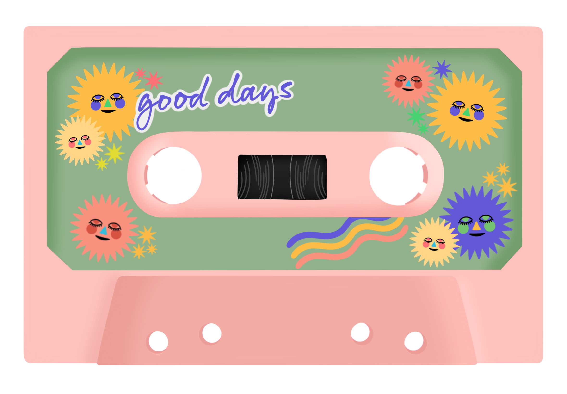
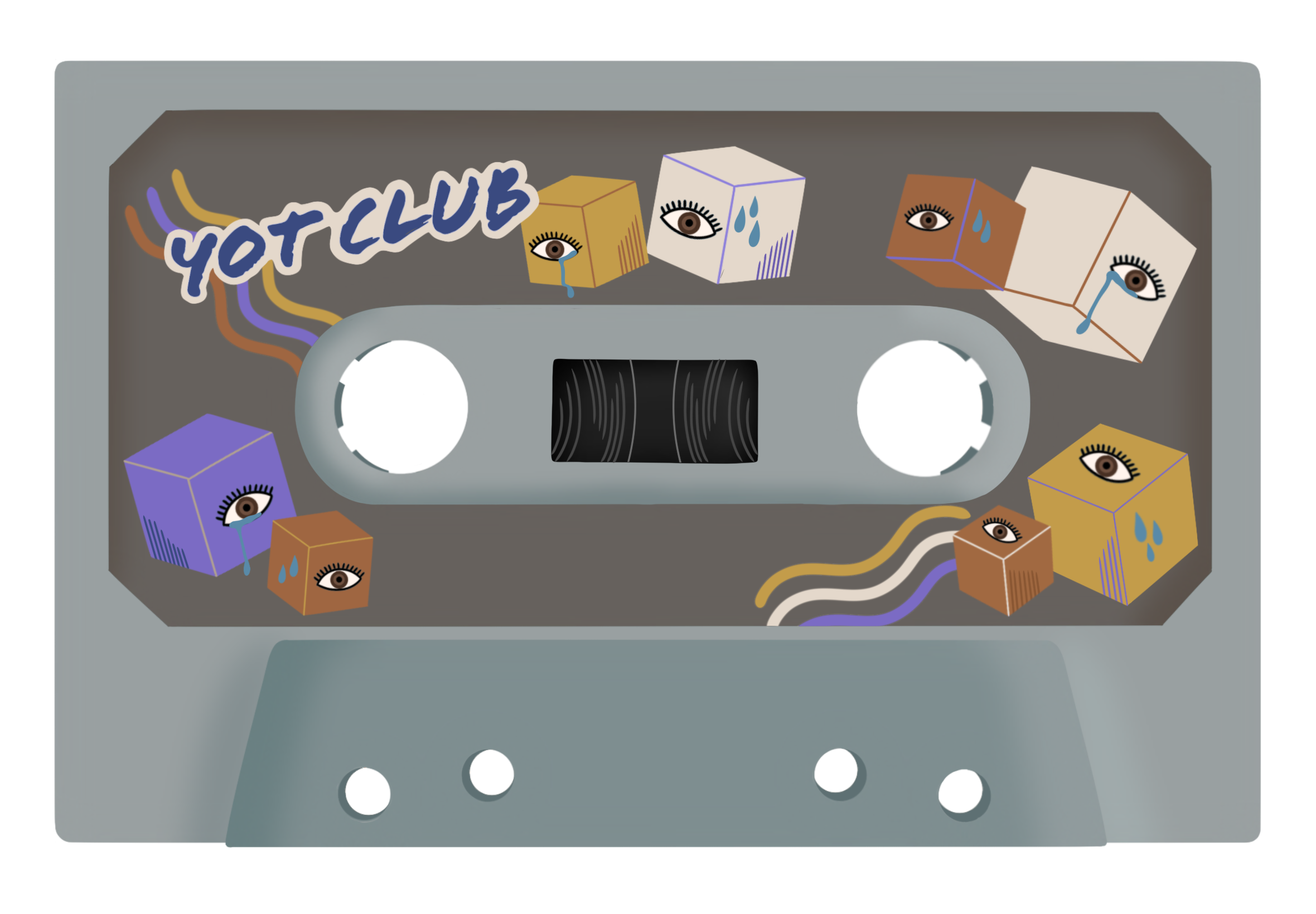
My final project concept is based off of my midterm project. In the previous midterm, I made a digital radio that played 2 meaningful songs. Each song displayed (what was supposed to be) a dynamic background of a personal memory associated with the songs. My final project builds off on this idea but with an added twist. You are able to customise your own cassette tape and based on your choices, it assembles a recommended playlist. There are 3 choices in each stage of customizing for the personalisation of your cassette and when finished, it plays a recommended playlist of 4 songs, each similar in genre. You can adjust the volume, use a skip function and reset the entire experience through physical means (buttons and potentiometer). Whilst my midterm involved a sense of personal intimacy, I tried to make this project evoke a more shared intimacy. Music is very personal to me and by sharing it with others, I am able to show a partial extension of my own identity which can be reciprocated by external users. Speaking from personal experience, it cements a bond quicker.

//arduino code:

int button1Pin = A2; 
int button2Pin = A3; 
int potentiometerPin = A0;

void setup() {
  // Start serial communication so we can send data
  // over the USB connection to our p5js sketch
  Serial.begin(9600);

  // We'll use the built-in LED as a status output.
  pinMode(LED_BUILTIN, OUTPUT);
}

void loop() {
  // Read button states and potentiometer value
  int button1State = digitalRead(button1Pin);
  int button2State = digitalRead(button2Pin);
  int potValue = analogRead(potentiometerPin);

  // Send data to p5.js
  Serial.print(button1State);
  Serial.print(",");
  Serial.print(button2State);
  Serial.print(",");
  Serial.println(potValue);

  delay(100); // Adjust delay as needed
}

This final project was so so painstakingly challenging and was such an arduous experience in general it took my soul and a chunk of hair by the time I was finished. Every portion of code had a bug and debugging it took a minimum of 1.5 hours (rarely as I wasn’t so lucky) and a maximum of 7 hours+. I will most likely never forget such an experience. The first portion – p5.js, was doable, yes there were countless debugging that was really frustrating but the cherry on the cake was the second portion – serial communication of the final project. The process of this entire final was tedious overall:

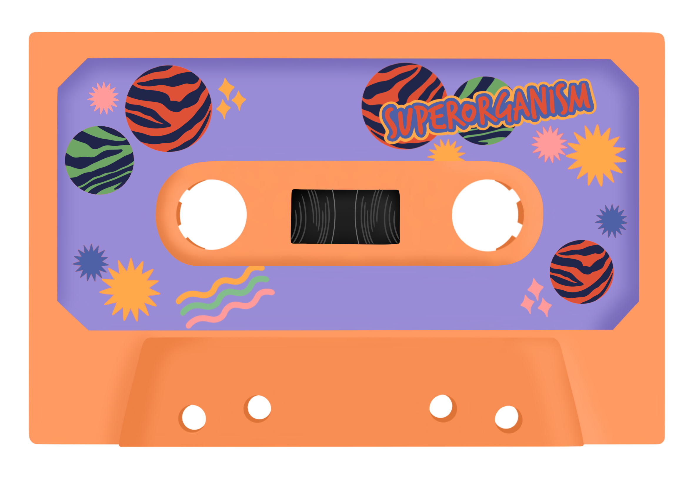
PROCESSES – ART STAGE:
I first created 3 playlists of 4 songs. Then using pinterest inspirations of vintage cassette tapes, I drew each stage: cassette base, cassette sticker, cassette detail using procreate. I illustrated specific combinations of these cassettes to equate to a certain playlist and I drew the details to correspond with the overall music vibe and aesthetic: (see below: 1) result1, 2) result2, 3) result3). As mentioned in my user-testing documentation section,  I wanted to create an animation of the cassette tape rolling when users entered the final stage: music playing. The only plausible way was to create a gif file containing such animation. Because there are 3 choices for each 3 stages and 3 different combinations users could select, it meant I had to create animations for a total of 27 cassettes, hence why it was so time consuming.

PROCESSES – P5.JS:
Essentially both coding experiences were one I do not want to remember… the endless bug fixes, the endless error messages on the console, it was just incredibly stressful. However the code that evoked the most stress and hence, I’m most proud of was attributing the corresponding gif files to every possible indices user could end up with – likewise with creating the cassette animations, there were 27 different combinations. This meant that the program had to store the index chosen at each stage and use this information to call upon a gif file with the corresponding index. This was one of those sections that took 7+ hours to debug and code. I didn’t know where to start and how, so, like I always did with previous assignments, I began researching and looking for codes that fulfilled similar instances on google. Then came the experimentation and checking using console.log. Through this I was able to learn syntax I had never encountered before and this acted as a sort of revelation for me. Here is the relevant code section:

//
const gifFilenameMap = { //attributing gif file pathway to user selected indices
//for cassetteBase[0]
  "0_0_0": "gifs/result1_prpl1.gif",
  "0_0_1": "gifs/result1_prpl2.gif",
  "0_0_2": "gifs/result1_prpl3.gif",
  "0_1_0": "gifs/result1_green1.gif",
  "0_1_1": "gifs/result1_green2.gif",
  "0_1_2": "gifs/result1_green3.gif",
  "0_2_0": "gifs/result1_grey1.gif",
  "0_2_1": "gifs/result1_grey2.gif",
  "0_2_2": "gifs/result1_grey3.gif",

//for cassetteBase[1]
  "1_0_0": "gifs/result2_prpl1.gif",
  "1_0_1": "gifs/result2_prpl2.gif",
  "1_0_2": "gifs/result2_prpl3.gif",
  "1_1_0": "gifs/result2_green1.gif",
  "1_1_1": "gifs/result2_green2.gif",
  "1_1_2": "gifs/result2_green3.gif",
  "1_2_0": "gifs/result2_grey1.gif",
  "1_2_1": "gifs/result2_grey2.gif",
  "1_2_2": "gifs/result2_grey3.gif",

//for cassetteBase[2]
  "2_0_0": "gifs/result3_prpl1.gif",
  "2_0_1": "gifs/result3_prpl2.gif",
  "2_0_2": "gifs/result3_prpl3.gif",
  "2_1_0": "gifs/result3_green1.gif",
  "2_1_1": "gifs/result3_green2.gif",
  "2_1_2": "gifs/result3_green3.gif",
  "2_2_0": "gifs/result3_grey1.gif",
  "2_2_1": "gifs/result3_grey2.gif",
  "2_2_2": "gifs/result3_grey3.gif",
};

//generates gif filename based on indices of selected cassette components
function generateGifFilename(baseIndex, stickerIndex, detailIndex) {
  return gifFilenameMap[`${baseIndex}_${stickerIndex}_${detailIndex}`]; //generating filename using map => e.g., 2_1_0
}

function determineResult() {
...
//generating filename (e.g., "1_2_3") based on indices of selected components
  const gifFilename = generateGifFilename(selectedBaseIndex, selectedStickerIndex, selectedDetailIndex);
  gifElement = createImg(gifFilename, "selectedGif"); // displaying selected gif on canvas
  gifElement.size(imageWidth, imageHeight);
  gifElement.position(imagePosition.x, imagePosition.y);
}

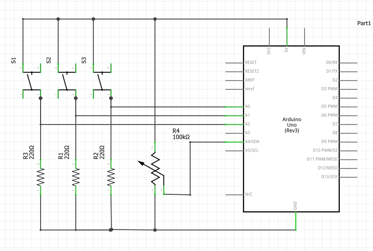
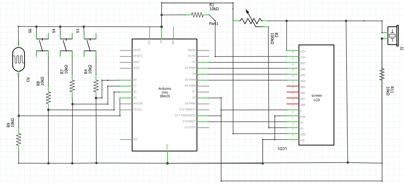
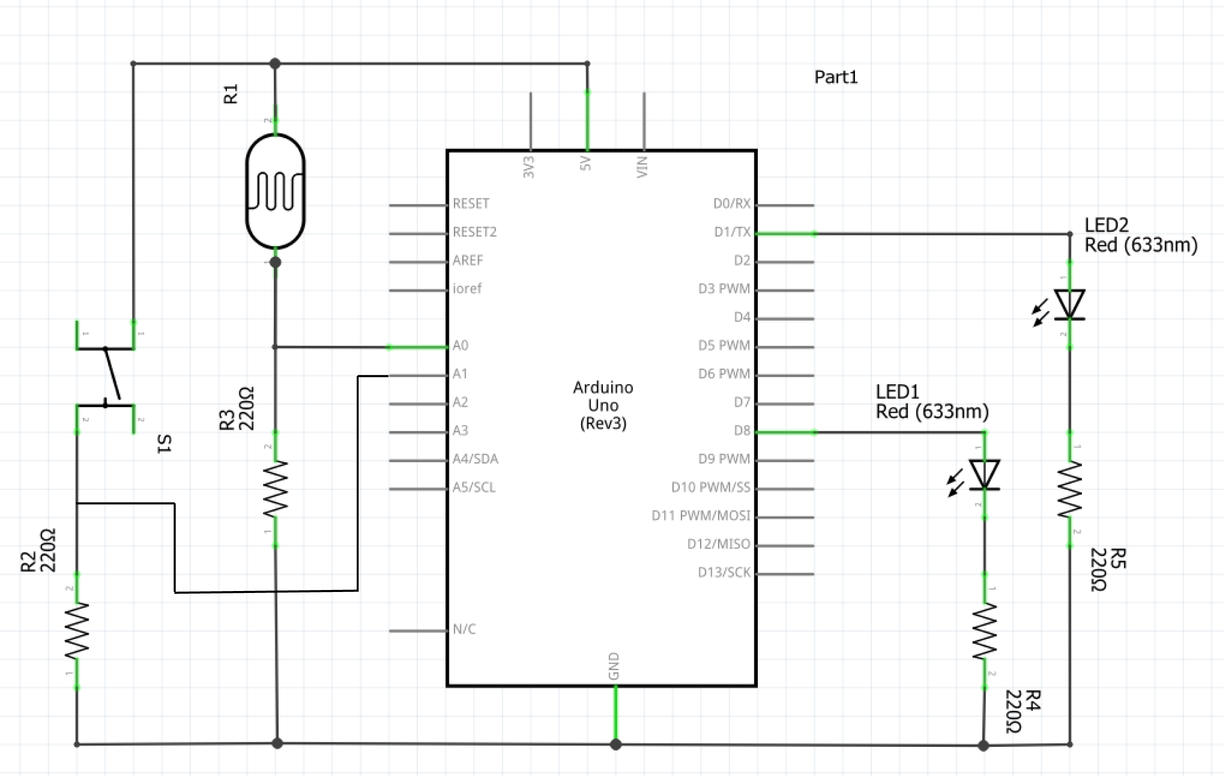
PROCESSES – ARDUINO + SERIAL COMMUNICATION:
Serial communication was one I had the most issues with. I used the existing serial communication code (in mang’s lecture notes) for both arduino and p5.js and altered it around my main piece of code however, problem 1) there seemed to be issues with p5.js and arduino exchanging data, hence it was impossible to know whether the physical wiring of the components on the breadboard was the problem or whether it was the code itself that was causing issues. 2) I continually experienced error messages stating that there was a network error hence I was unable to connect to a serial port. Both cases required patience, calmness and perseverance and through this it was engrained into me again the importance of console logging when debugging faulty code. At the start, I wasn’t able to understand the serial communication code that was provided but after the completion of my final project, everything kind of clicked into place.

Regarding attributing functions to the physical components: 2 push buttons and a potentiometer, I was also having major problems with applying my desired functions: play/pause, skip forward, skip backward, to the push buttons. Mapping the volume to the potentiometer value was really easy as something like it had already been done for the serial communication assignment. For the rest, it was a nightmare. I think it was the structure of the code and the specific manner in which I coded that caused so many breakdowns and errors. In the end I was incredibly short for time and so was forced to compensate and only code 1) resetToInitialState, 2) skip forward on loop. when coding for the function: resetToInitialState, 2 problems occurred: 1) gif image appearing over initial state, 2) sound continuing to play regardless of being set to its initial state. With extensive experimentation, I realised that creating new variables to keep track of the states of both the gif and sound was the most simplest and most rational solution – here is the relevant code:

let gifElement; (ADDED) 

//within function determineResult() 
if (gifElement) { (ADDED) 
  gifElement.remove(); //remove existing gifElement if it exists 
} 

const gifFilename = generateGifFilename(selectedBaseIndex, selectedStickerIndex, selectedDetailIndex); 
gifElement = createImg(gifFilename, "selectedGif"); // displaying selected gif on canvas (ADDED) 
gifElement.size(imageWidth, imageHeight); (ADDED) 
gifElement.position(imagePosition.x, imagePosition.y); (ADDED) 

/////////////////////////////////////////////////////////////////////////////////////
let shouldPlayNextSound = true; //(ADDED) 

//within function playNextSound()
if (shouldPlayNextSound) { //(ADDED)
  currentSoundIndex++; // increment sound index
  if (currentStage === 4 && currentSoundIndex >= result1.length) {
    determineResult();
    currentSoundIndex = 0; //reset to the beginning if end is reached
  }
}

//within function resetToInitialState()
shouldPlayNextSound = false; //disable skip function (ADDED)

//stopping all currently playing sounds
for (let i = 0; i < result1.length; i++) {
result1[i].stop();
}
for (let i = 0; i < result2.length; i++) {
result2[i].stop();
}
for (let i = 0; i < result3.length; i++) {
result3[i].stop();
}
shouldPlayNextSound = true; //enable skip function (ADDED)

FINAL REFLECTIONS + FUTURE IMPROVEMENTS:
Whilst it was the most nerve wrecking, anxiety inducing overall experience, since persisting bugs were fixed the day of the IM show, I was quite proud of what I have completed. Whilst the coding aspect of this project was beyond challenging, I can’t deny that it was lowkey fun at the same time – creating a project that involves my passion. To me, it certainly felt like a large leap in the level of difficulty, compared to my midterm project, and this was more so why I am proud of the finished result. For future improvements on the project, perhaps there could be a personality test which based on your selected answers allocates you to a specific design for each stage of the cassette customisation. This way the experience maintains for longer. I also think it builds more excitement and anticipation as to what cassette you’ll end up with. Improvements for the physical aspect of the project would be to build a radio with more extensive functions, like originally planned.

Regarding improvements for future IM projects, I am incredibly motivated to put thought into the building of an exterior because that, at the end of the day, is what can elevate user experience. Since it was my first time both showcasing and attending an IM show, I experienced somewhat of an epiphanous moment. In future classes I will be more mindful in creating a more immersive user experience that is able to appeal to a wider body of people, because whilst mine did have some sort of user experience, it was more so stagnant with limited interaction compared to the other projects that were showcased. Overall I think it was an excellent opportunity to understand the fundamentals of what Interactive Media embodies and it has further propelled my motivation to learn in depth creative coding.

week 11&12 – (final project) preliminary concept | idea finalization | user testing

PRELIMINARY CONCEPT:
I wanted to do some brainstorming regarding the concept of my final project. I wanted to do something that wasn’t too ambitious (considering the myriad of deadlines as a result of finals week and the limited time constraints). I think because I couldn’t think of a theme, ideas were very vast which didn’t help. After some major considerations and scrapping of multiple ideas, I came to the conclusion that I would want to build off on my midterm project to create a physical radio that is controllable through i.e., buttons, potentiometer, power switch. Output would be digital and input would be both digital and physical.

FINALIZED CONCEPT:
I thought creating a purely physical radio with a digital output would not be enough interactivity or at least a meaningful interaction, hence I wanted to perpetuate intimacy. I love music and (to me) what is more intimate than sharing your favourite playlists/ artists with others? I decided to make my final project a 2-part: 1) determine corresponding mood/ personality through personalizing their own cassette tape, 2) according to results, a playlist of 4 songs would be curated – this way there is more intimate and meaningful back and forth. Essentially it would work like those buzzfeed quizzes except physical input via push buttons are possible.

Total physical components would include 3 push buttons and a potentiometer for volume control. My arduino program will read the potentiometer value and buttons’/switch’s state and send the information to p5.js via serial communication. When p5.js receives information about the button’s push state, it will call upon its corresponding function, i.e., pause/play, skip forward/ backward. I will use the mapping function to map the potentiometer value to the volume so that whenever the potentiometer is toggled, p5.js will continuously receive its p value and adjust the volume accordingly. With regards to my p5 program design, I intend to have a cassette displayed in the middle with “select” and arrows buttons. Since users will select designs for each of the 3 stages, the “select” button will store user choices in a separate variable so as to assign a “result1/2/3” playlist. Although undecided, I intend to have a separate display screen for when the recommended playlist sounds to indicate the change of focus from p5 to the actual physical components.

week 11 – group assignment (maya)

1st exercise: 
We used the existing example: Week 11 Bidirectional serial communication(p5js Sketch) to fulfill the 1st exercise. We created a new variable “moveEllipse” to map the alpha value to the canvas width. We then used our variable as the x-position of the ellipse, successfully enabling the ellipse to move from one edge to the other as the potentiometer value increased.

let moveEllipse = map(alpha, 0, 1023, 0, width);  
//
stroke(0);
ellipse(moveEllipse, height / 2, 60);

2nd exercise:
Editing that same example, we added the bouncing ball javascript from p5.js: https://editor.p5js.org/icm/sketches/BJKWv5Tn . The LED becomes brighter when the ball moves towards the right edge of the canvas. Conversely, the LED becomes dimmer when the ball moves towards the left edge of the canvas. We edited the arduino to replace digitalWrite with AnalogWrite to enable the control of the LED brightness.

//
let x = 320;
let y = 180;
let xspeed = 3;
let yspeed = 2;
let r = 25;

//
  ellipse(x, y, r*2, r*2);
  // mapping brightness to canvas width
  let rightValue = map(x, 0, width, 0, 255);
  right = int(rightValue);
  //
  x += xspeed;
  y += yspeed;
  if (x > width - r || x < r) {
    xspeed = -xspeed;
  }
  if (y > height - r || y < r) {
    yspeed = -yspeed;
  }
}

3rd exercise: https://youtu.be/YFucULMGidI

I took the main structure of the code from the exercise we looked at in class- where we had to press our spacebar to connect to our board. There, I added the code with the bouncing ball given to us through this link: https://editor.p5js.org/aaronsherwood/sketches/I7iQrNCul

The approach was to call bounceBall() function once the serial is activated, where p5js will continuously send touch value (1 means it touched the ground and 0 means it’s above ground) to the arduino. In return, the arduino would send lightStatus value (the input read from the light sensor). If the received value is bigger than 500, the wind blows from left to right and right to left if the value is smaller than 500.

arduino:

int ledPin = 5;
int lightPin = A1;
int lightStatus;

void setup() {
  Serial.begin(9600);
  pinMode(ledPin, OUTPUT);
  pinMode(lightPin, INPUT);

  // start the handshake
  while (Serial.available() <= 0) {
    digitalWrite(LED_BUILTIN, HIGH);
    Serial.println("0");
    delay(1000);
    digitalWrite(LED_BUILTIN, LOW);
    delay(100);
  }
}

void loop() {
  while (Serial.available()) {
    digitalWrite(ledPin, HIGH);

    int ledLight = Serial.parseInt();
    lightStatus = analogRead(lightPin);
    if (Serial.read() == '\n') {
      digitalWrite(ledPin, ledLight);
      delay(50);
      digitalWrite(ledPin, LOW);
      Serial.println(lightStatus);
      delay(5);
    }
  }
  digitalWrite(LED_BUILTIN, LOW);
}

week 11 – reading reflection

I agree with the author’s perspective that adopting a discreet design for “aids” may not be the optimal choice. This approach perpetuates the notion that these aids conflict with societal norms and thereby draw undue attention, and so should be concealed. This inadvertently contributes to the stigmatization of disabilities in general, reinforcing the idea that it is something to be embarrassed about. Nevertheless, I understand that individuals with disabilities may desire discrete designs due to probable negative attention towards their conditions. Society often reacts adversely to things that deviate from the norm, leading some to prefer aids that blend in. Considering the limited market for disability-related products, it may be pragmatic to focus on designs that cater to the majority rather than a smaller fraction of individuals who embrace their disabilities and seek products that stand out.

I resonate with the notion that the lack of stigma surrounding bad eyesight is attributed to the normalization of glasses as a fashion accessory. The integration of glasses into everyday wear, regardless of bad/ good eyesight, has contributed to their acceptance and reduced their visibility as a medical aid. This normalization could serve as a valuable model for the design of other aids, reducing the perception of these devices as conspicuous or abnormal. The article’s observation about the exclusion of designers in the creation of aids, such as prosthetics and hearing aids, is particularly poignant. It seems paradoxical that individuals who themselves may use aids are not involved in their design. This exclusion perpetuates the categorization of aids as purely medical products, further intensifying the stigma associated with bodily “aids”. Inclusion of designers with personal experiences of using aids could offer valuable insights, bridging the gap between functionality and aesthetic appeal and challenging the prevailing stigmas associated with these essential tools.

week 10 – reading reflection

The first reading was definitely intriguing and despite its somewhat comical tone, I believe it highlights an important issue that is growing ever so prevalent in our contemporary times. Pictures under Glass technology, I believe, isn’t a so far-fetched notion and could potentially occur in the nearer future. Technological advancements are facilitated for human convenience and so ultimately, I feel as though it’s used to increasingly replace human capabilities. In the case of the first reading, ‘pictures under glass’ undermines human capability of touch and it overlooks the importance of tactile richness. Stimulation, especially new stimulation, is vital for strengthening neural pathways and promoting cognitive growth and as such, these novel experiences contribute to cultivating a shaper mind, creating a foundation for a more resilient and adaptable cognitive capacity. However if such experiences are massively condensed to something homogenous like this picture under glass technology, we lose such cognitive abilities. In this sense, whilst technological advancement is good, it is worrying as it feels like we are on a path of neurological de-evolution.

In delving into the second reading, the contrasting reactions among readers regarding the trajectory of interactive media resonates with the profound (aforementioned) notion. The shared call for a forward-thinking approach, aligning innovation with our human experiences, I believe, becomes even more relevant in this context. Such a notion ultimately strikes a chord with my concerns about the impact of technology on our lives. The discussion on the potential loss of creativity and emotional depth in a future dominated by touchscreens and voice commands prompts personal reflection on the role of technology in my own experiences. Navigating this dynamic landscape, the reflections serve as both a call to action and a personal invitation to consciously shape a future where technology enhances, rather than diminishes, the richness of both physical and emotional existence.

week 10 – group assignment (Jason)

Video: https://youtu.be/d6cVEQlEJnk

For our group assignment, we weren’t sure in what way a sensor could be implemented to generate musical notes, so we first brainstormed on an instrument on which we could base this assignment: the accordion. To replicate the keys, we decided to use switches (buttons) and for “bellows” we decided on the flex sensor. We first planned out our schematic, first mapping out the switches, resistors then the analog (connecting) wires. However when actually delving into the construction of the breadboard and subsequently the coding aspect, we ran into a few problems that required us to improvise. We first realized through using the serial monitor that the output generated by the flex sensor was incredibly jittery and inconsistent. It was hard to make out a constant value range. Hence we decided to use an alternative sensor: the photoresistor. Ultimately our approach was predominantly to improvise. Once we had resolved our main code, we decided to utilize the LCD, on a whim, to show “:)” or “:(” pertaining to specific conditions. This required us to do some research on how the LCD is connected to the breadboard, and the code used to display characters: https://docs.arduino.cc/learn/electronics/lcd-displays

HOW IT WORKS:
3 buttons play different notes. The range in tone of the note varies according to the photoresistor – the more the light is conceived, the higher the note is played. Subsequently, the LCD shows “:)” when the tone frequency, determined by the analog reading from the flex sensor, is higher than the previous frequency; otherwise, it displays “:(“. This comparison is specific to each color (red, green, blue), and the frequency values are mapped accordingly.

Schematic:

Arduino Code:

// include the library code:
#include <LiquidCrystal.h>

// initialize the library by associating any needed LCD interface pin
// with the arduino pin number it is connected to
const int rs = 12, en = 11, d4 = 5, d5 = 4, d6 = 3, d7 = 2;
LiquidCrystal lcd(rs, en, d4, d5, d6, d7);

int buzzerPin = 8;
int redpin = A0;
int greenpin = A1;
int bluepin = A2;
int phopin = A3;  //
float prev=0;

void setup() {
  // put your setup code here, to run once:
  pinMode(buzzerPin, OUTPUT);
  pinMode(redpin, INPUT);
  pinMode(greenpin, INPUT);
  pinMode(bluepin, INPUT);
  pinMode(phopin, INPUT);  //
  lcd.begin(16, 2);
  Serial.begin(9600);
}

void loop() {
  // put your main code here, to run repeatedly:
  int redState = digitalRead(redpin);
  int greenState = digitalRead(greenpin);
  int blueState = digitalRead(bluepin);
  int flexState = analogRead(phopin);  // 350 to 1000
  float redvariance = 130.8 + map(flexState, 350, 1050, 0, 130.8);
  float greenvariance = 261.6 + map(flexState, 350, 1050, 0, 261.6);
  float bluevariance = 523.2 + map(flexState, 350, 1050, 0, 523.2);
  if (redState == HIGH) {
    tone(buzzerPin, redvariance);
    if (higherThanPrev(prev, redvariance)) {
      lcd.print(":)");
    } else {
      lcd.print(":(");
    }
    prev = redvariance;
    delay(100);
  } else if (greenState == HIGH) {
    tone(buzzerPin, greenvariance);
    if (higherThanPrev(prev, greenvariance)) {
      lcd.print(":)");
    } else {
      lcd.print(":(");
    }
    prev = greenvariance;
    delay(100);
  } else if (blueState == HIGH) {
    tone(buzzerPin, bluevariance);
    if (higherThanPrev(prev, bluevariance)) {
      lcd.print(":)");
    } else {
      lcd.print(":(");
    }
    prev = bluevariance;
    delay(100);
  } else {
    noTone(buzzerPin);
  }
  lcd.clear();
}

bool higherThanPrev(float prev, float now) {
  return prev < now;
}

Overall we were quite pleased with the end result, even more so with our LCD addition. However, we felt as though it was difficult to classify our project as a musical instrument since, despite the complex interplay between analog/ digital sensors, the sounds produced were less “musical” in a sense.<span style=”color: #000000;”> </span><span style=”color: #000000;”>Furthermore, we realized that whilst the tone of the sound produced by the blue switch was very clearly affected by the amount of light perceived by the photoresistor, this was not the case for the red switch</span>. It was much harder to distinguish a change in the tone of the sound. We believe it is because the red button signals the C note in the 3<sup>rd</sup> octave, and the blue one signals the C note in the 5<sup>th</sup> octave. Since the frequency of octaves is calculated with the formula “Freq = note x 2<sup>N/12</sup>”, the changes in frequencies mapped to the notes will be more significant as octaves increase. For future improvements, especially with regards to its musicality, perhaps we could have each button play a series of notes, hence the 3 switches would produce a complete tune. Rather than mapping ranges for the photoresistor, we could choose a (more than/ less than) specific value. For example, in a dark room, the complete tune would be played in a lower key whilst in a bright room, the tune would play in a higher key.

week 9 – analog input & output

Video: https://youtu.be/JsG16pEle1I

For this assignment, I decided to use a photoresistor as my analog sensor. I wanted to represent and draw a comparison of our mentality during day and night i.e., I wanted to represent alertness and calmness through LED lighting patterns. When photoresistor sensor value (psv) is between 20-150, the yellow LED will blink rapidly. If the psv is at 0, the blue LED will blink slowly. The button applies these blinking patterns to different LEDs, meaning when the button is pressed and psv is between 20-150, the blue LED will blink rapidly whilst psv at 0 will cause the yellow LED to blink slowly. Through this assignment, I was able to grasp a stronger sense of the arduino syntax but most importantly, I became more capable of working the breadboard to make correct connections. Furthermore I think I’ve cemented my abilities in reading schematics which has enabled me to make such connections on the breadboard without taking a glimpse at the fritzing breadboard layout, which I’m really pleased about. Whilst I still struggled with the coding aspect, I really enjoyed and appreciated this assignment.

Schematic:

Arduino code snippet:

if (photoState >= 20 && photoState <= 150) {
  flickerLight(currentLed);  //flickerLight(yellowPin)
  digitalWrite(currentLed == yellowPin ? bluePin : yellowPin, LOW);
  // 1) currentLed == yellowPin => checks if value is yellowPin
  // 2) ? bluePin : yellowPin => if 1st condition == true, turn off bluePin, otherwise turn off yellowPin
} else if (photoState <= 10) {
  digitalWrite(currentLed, LOW);
  flickerDark(currentLed == yellowPin ? bluePin : yellowPin);
}

if (buttonState == HIGH) {  // if button is pressed, toggles value of "currentLed" between 'yellowPin' & 'bluePin'
  currentLed = (currentLed == yellowPin) ? bluePin : yellowPin;
  delay(200);
}

I had the hardest time implementing this change: button applies blinking patterns to different LEDs. And through very extensive research I learned about the conditional (ternary) operator. I realised after hours of experimenting and researching that I needed to create a variable to keep track of the LED state: “currentLed”. By incorporating this with the conditional (ternary) operator, I was able to create a mechanism where if the button was pressed, flickerLight/ flickerDark would correspondingly be applied to the opposite LED pin. Whilst it was definitely a pain in the sense that I struggled with this specific implementation for hours, I was very pleased with the end result. With regards to future improvements/ projects, I’d like to create a moodlight. I could use the tricolour LED, switch and trimpot. The trimpot could control the colour displayed and the switch, likewise to this assignment, could afftect the flicker pattern displayed.


week 9 – reading reflection

I wanted to highlight the juxtaposition of “Making Interactive Art: Set the Stage, Then Shut Up and Listen” and “Physical Computing’s Greatest Hits (and misses)” as it offers a comprehensive view of the delicate balance required in the realm of interactive art and physical computing. The former reading emphasizes the importance of creating a space for open interpretation, urging artists to resist the urge to over-explain their creations. I think this really resonates with the idea that true interactive art is a living conversation, where the audience actively contributes to the experience. On the other hand, the latter, showcasing recurring themes in physical computing projects, reinforces the notion that repetition doesn’t equate to stagnation but rather serves as a canvas for individual interpretation and innovation. Themes like theremin-like instruments or video mirrors may be recurrent, but each iteration offers a unique perspective, inviting creators to infuse their individuality into well-trodden paths.

What stood out the most to me was the encouragement to embrace recurring themes not as constraints but as opportunities for creative expression. The notion that physical computing provides a playground for creativity, as expressed in response to “Physical Computing’s Greatest Hits (and misses),” aligns seamlessly with the idea of setting the stage and letting the audience take the spotlight. I think this serves a profound reminder that even within established themes, there is ample room for exploration and originality. Hence, the blend of such perspectives encourages a dynamic approach to interactive art, where established concepts serve as a foundation rather than a limitation, and the true beauty emerges from the fusion of technology, creativity, and the unique interpretations of those engaging with the art.

week 8 – unusual switch

This project took a while for me to wrap my head around mostly because of the stipulation: creative and unusual, I guess I was overthinking what classifies as unusual and what does not. I realise that the prompt specifies no use of hands but for some reason I interpreted that as no use of hands to regularly trigger a button/ switch etc., as a means to activate the led… so hopefully my simple project still qualifies. I interpreted the light to embody a positive emotion since it radiated a warm and homey glow. I wanted to connect this to a meaningful something whilst making it so that it could act as a switch, and with my sleep-deprived brain, this really stumped me. The only viable “something” I could think of was relating this “switch mechanism” to the arts, which I’m moderately passionate about. And naturally this transformed and manifested into the idea of using scissors as a switch.

https://youtube.com/shorts/cSCZFdWsqJQ?feature=share

The whole circuit itself was not too difficult to create – it consisted of a green light, ground wire, resistor, a red wire and 2 more wires to connect from the breadboard to the scissors. The one thing I will say is that I had no no conductive tape or aluminium foil and so I had to make do with using normal tape to wind the wires to their appropriate positions on the scissors. Because of this, it wasn’t too reliable since the wires were prone to shifting, and so ultimately it would’ve worked better through use of a more stable medium. Whilst I’m happy about this assignment, I do have doubts on the “creativity” aspect. I also propose a more meaningful and idea-wise, stronger alternative. Perhaps I could’ve attached aluminium foils/ conductive tape to my chest and hand. Whenever I would place my hand over my heart, the led would light up.

week 8 – reading response

I think it’s especially interesting how wide the breadth of psychology, which is profoundly underpinned by Norman’s “Emotion and Design: Attractive Things Work Better”, really is. Norman’s emphasis on emotions highlights the significance of aesthetics in enhancing user functionality, and this is all the more important to note is since such a concept really challenges the conventional belief that aesthetics should take a backseat to functionality in design. Her specific delineation regarding affect, aesthetics and functionality makes sense and the reason why it was illuminating was because this wasn’t something I consciously and actively thought about when handling a product. It’s completely natural for positive affect to increase tolerance for minor flaws in user functionality because we are in a more forgiving headspace for such a situation. However, negative affects eliminate this state of mind, hence it makes more sense to prioritise user functionality over aesthetics in products that warrant negative affects.
This same concept can be applied to Margaret Hamilton’s groundbreaking work as exemplified in the second reading whereby it highlights the clear intersection between psychology and user functionality in high-stake situations. Her meticulous software development for the Apollo mission integrated rigorous testing and fault tolerance to ensure usability under extreme conditions i.e., conditions that are prone to evoking negative affects. This ultimately aligns with the psychological principles discussed in Norman’s text, illustrating that the design of critical systems must consider users’ emotional states and its subsequent impact on usability.