Concept:
My final project mostly stays true to its initial goal – except I combined both of my ideas. This project is an interactive art project that allows you to both visualize and create your own visual art. At core of its project are sin wave structures, which in simple term serve as fundamental graphical elements (used OpenGL for 3D) to create dynamic flowing patterns. The user is free to control them with various gestures and interactions all of which are natural with our hands to perform. For example, pinching your thumb and index finger together and moving your hand up and down. There is also a layer of Arduino integration which serves to expand the functionality with ultrasonic sensor, dictating the zoom level of the canvas, and three buttons which serve different functions. Red one is responsible for toggling Trail mode which lets you create a dynamic painting, the yellow one lets you stop the drawing to then save your work with green button as a form of a screenshot. This simple concept can be expanded to bigger scales. I could imagine this implemented in science or other classes where we demonstrate different mathematical equations or models with which students are able to interact with simple gestures. Conversely, they are able to adjust individual parameters and really see whats going on under the hood. The gestures make it much more intuitive and fun to do so. Moreover, they are free to experiment with trails, creating abstract drawing of their own and coming up with creative ways to combine and fuse different shapes and patterns to come up with beautiful renders.
Images:
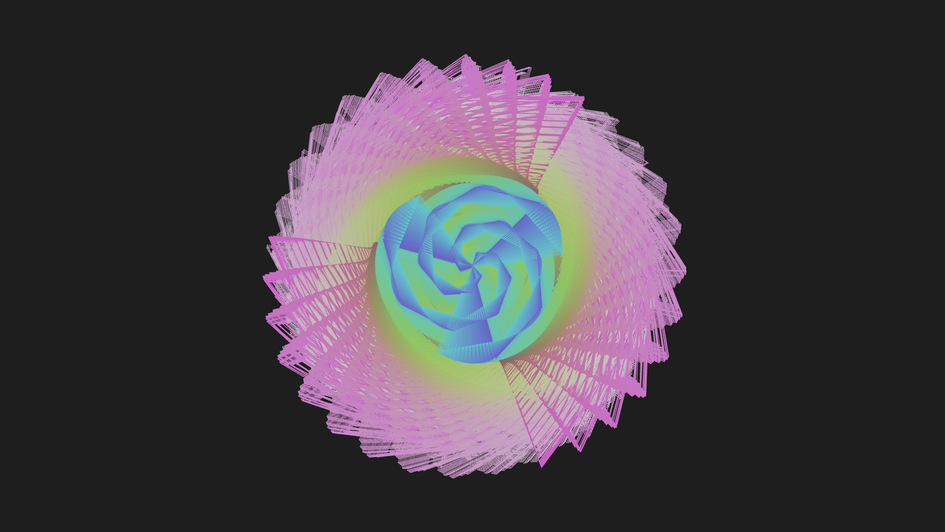
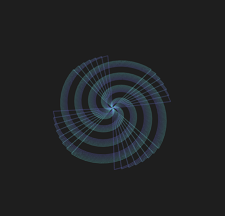
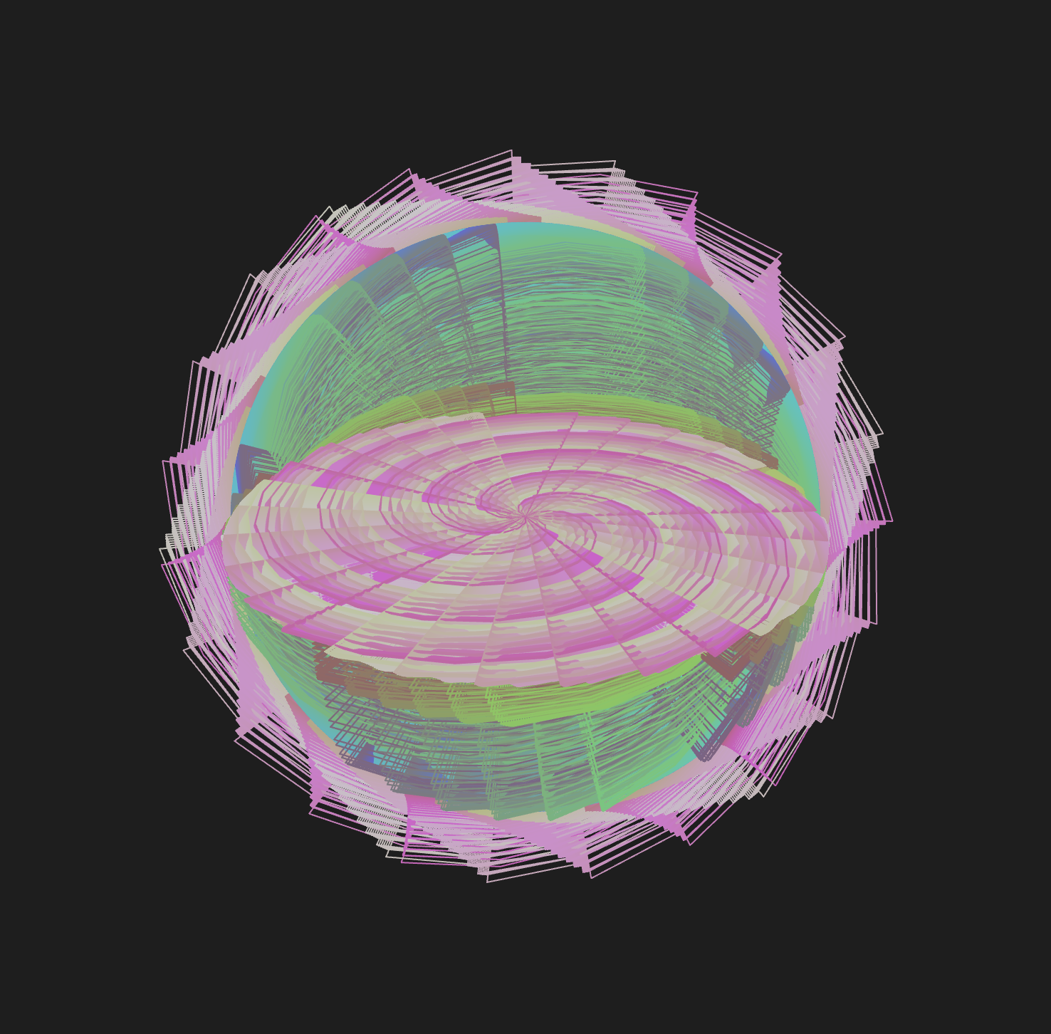
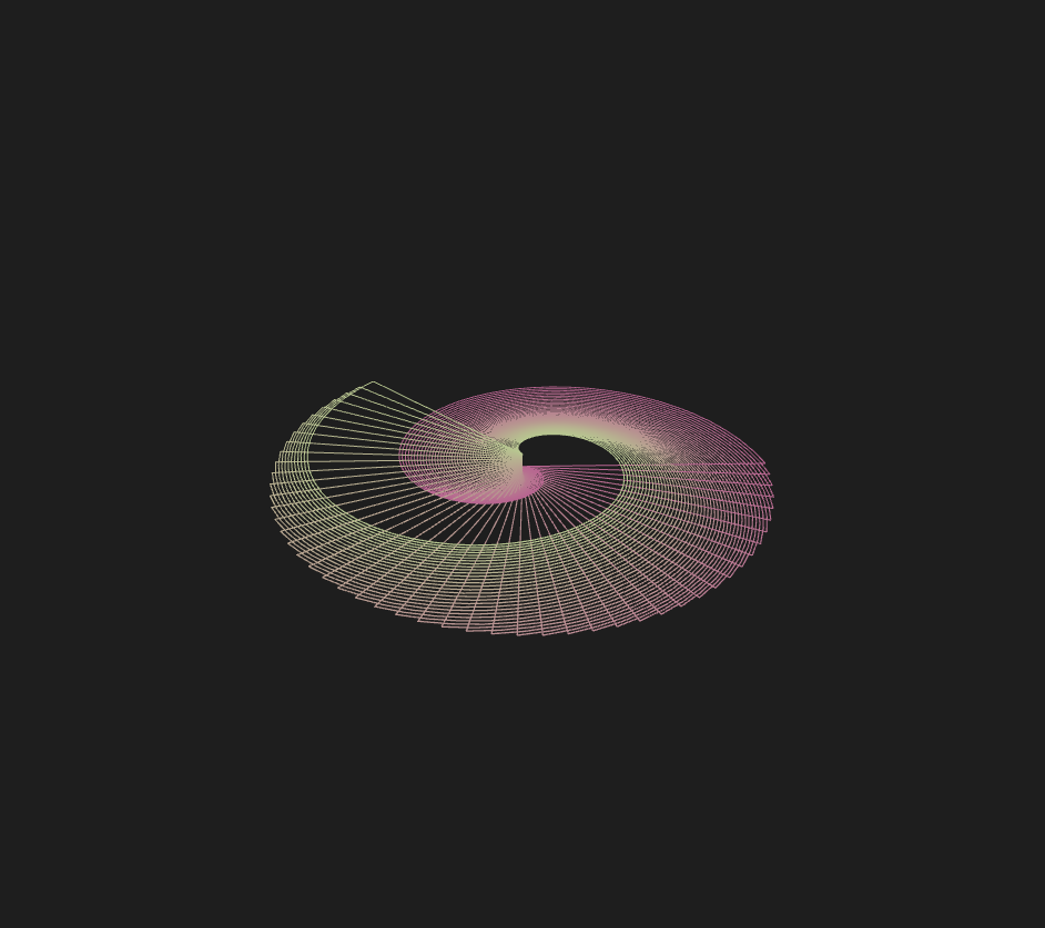
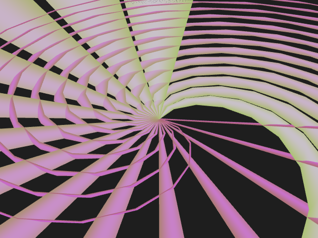
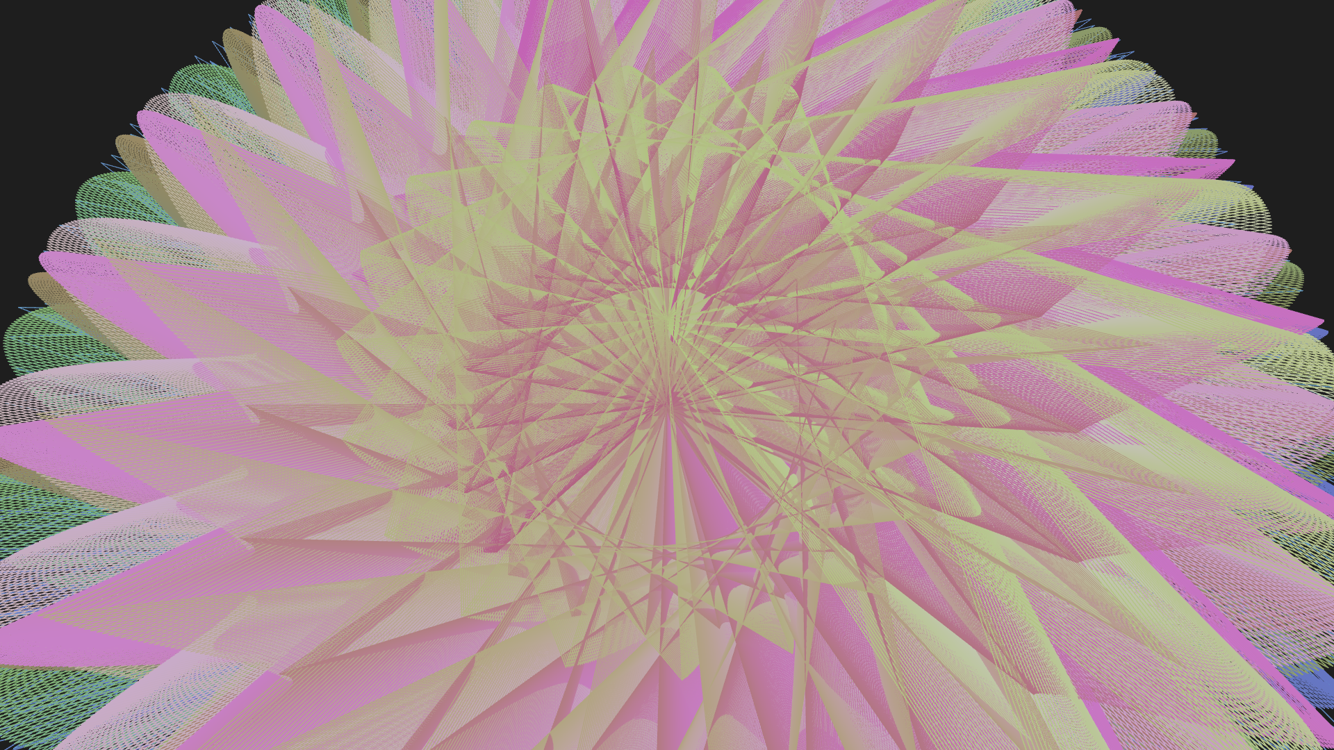
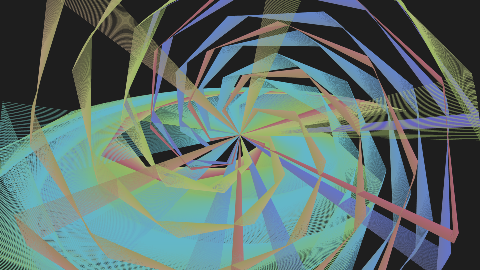
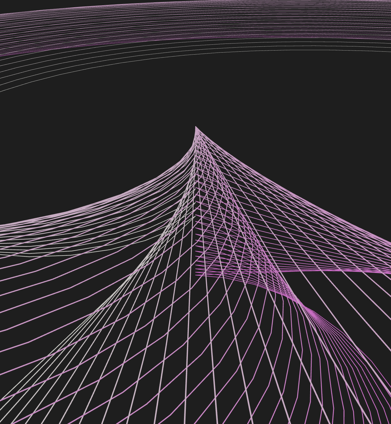
Example sketches:
UI:


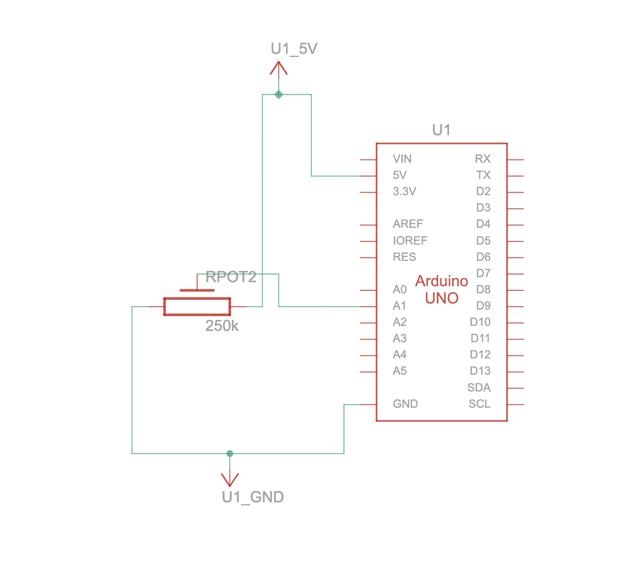
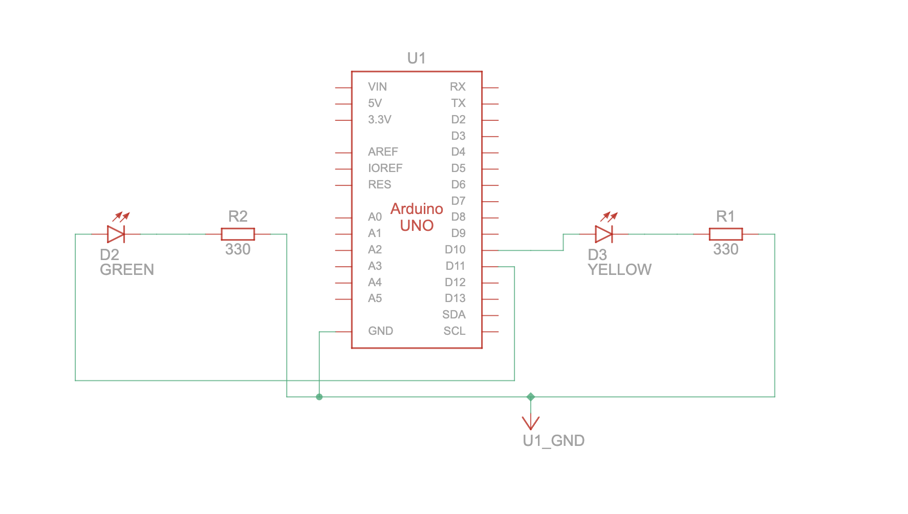
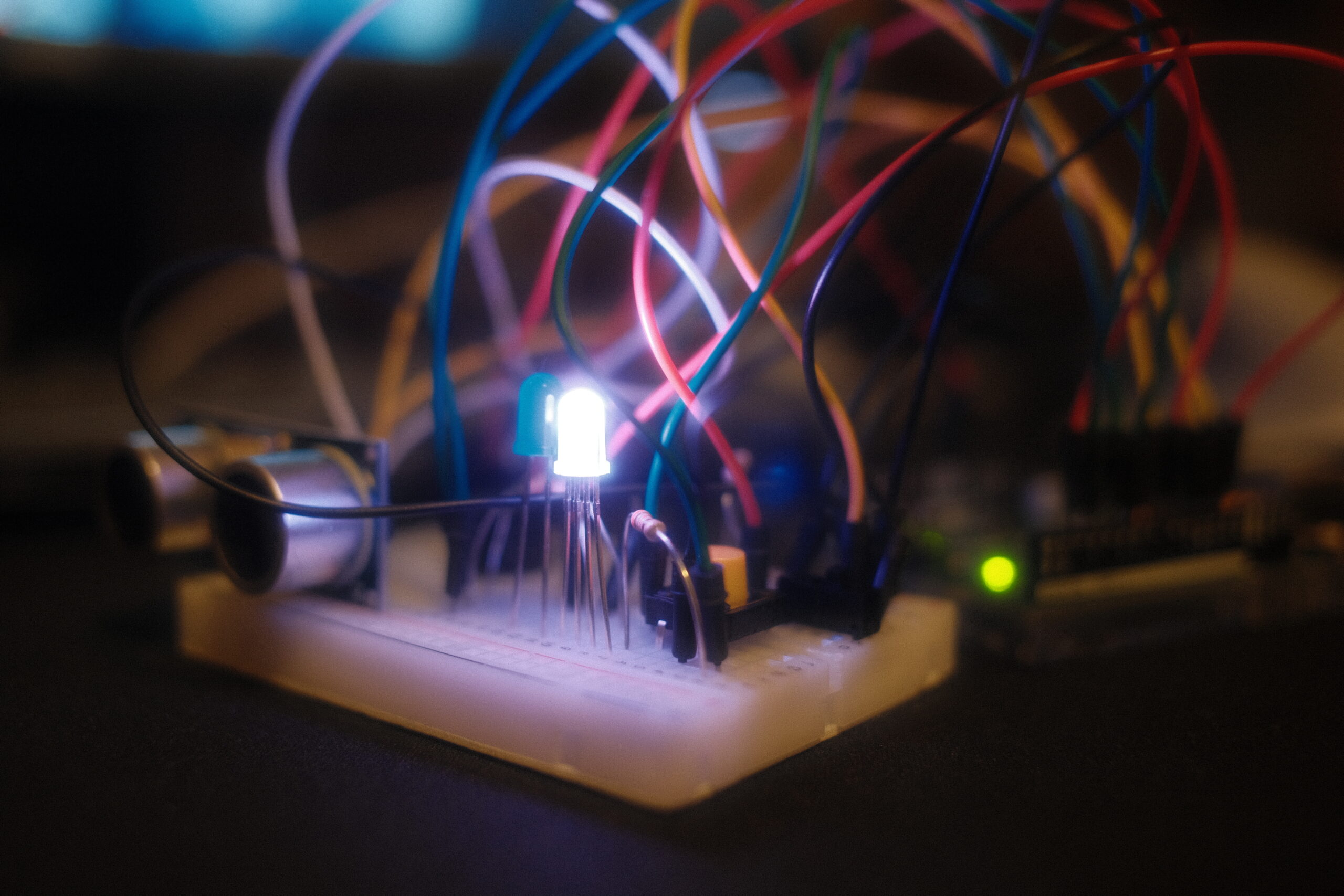
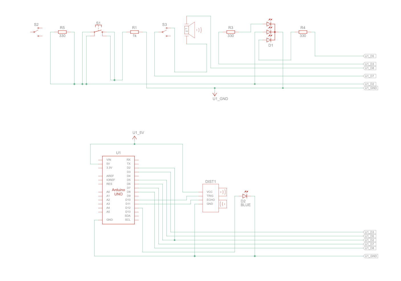
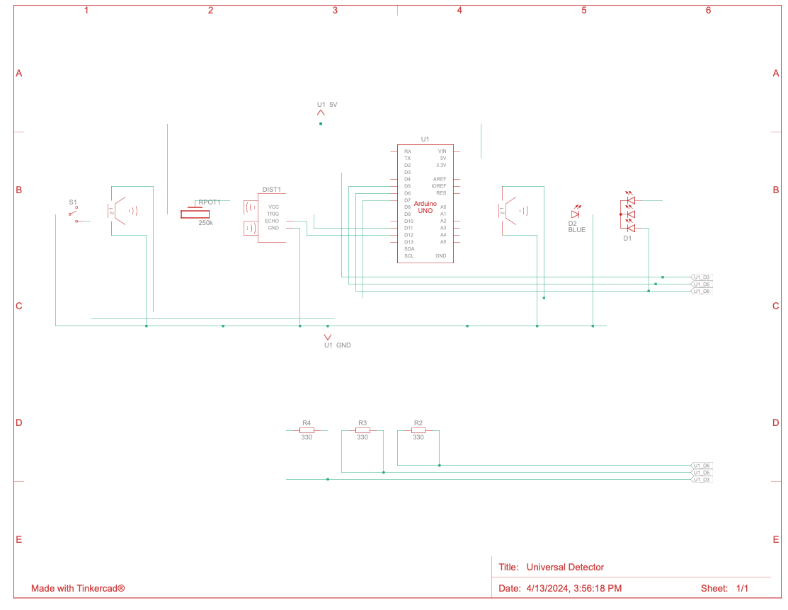
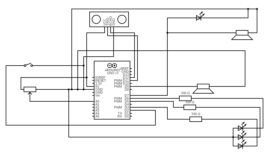
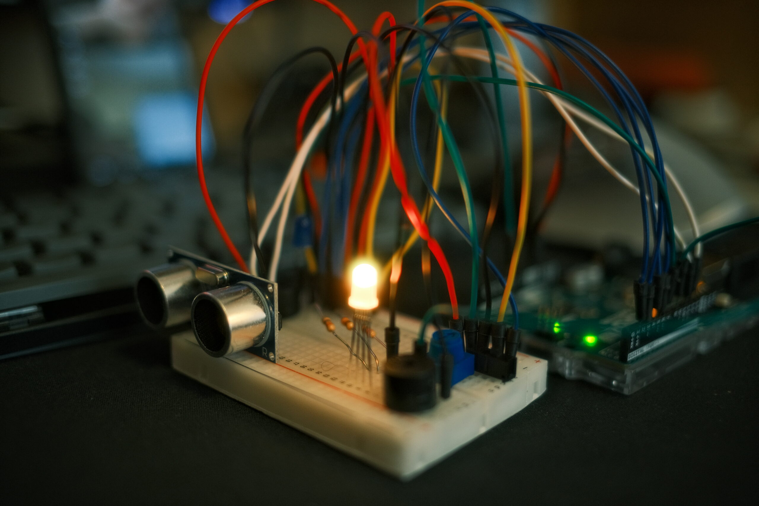
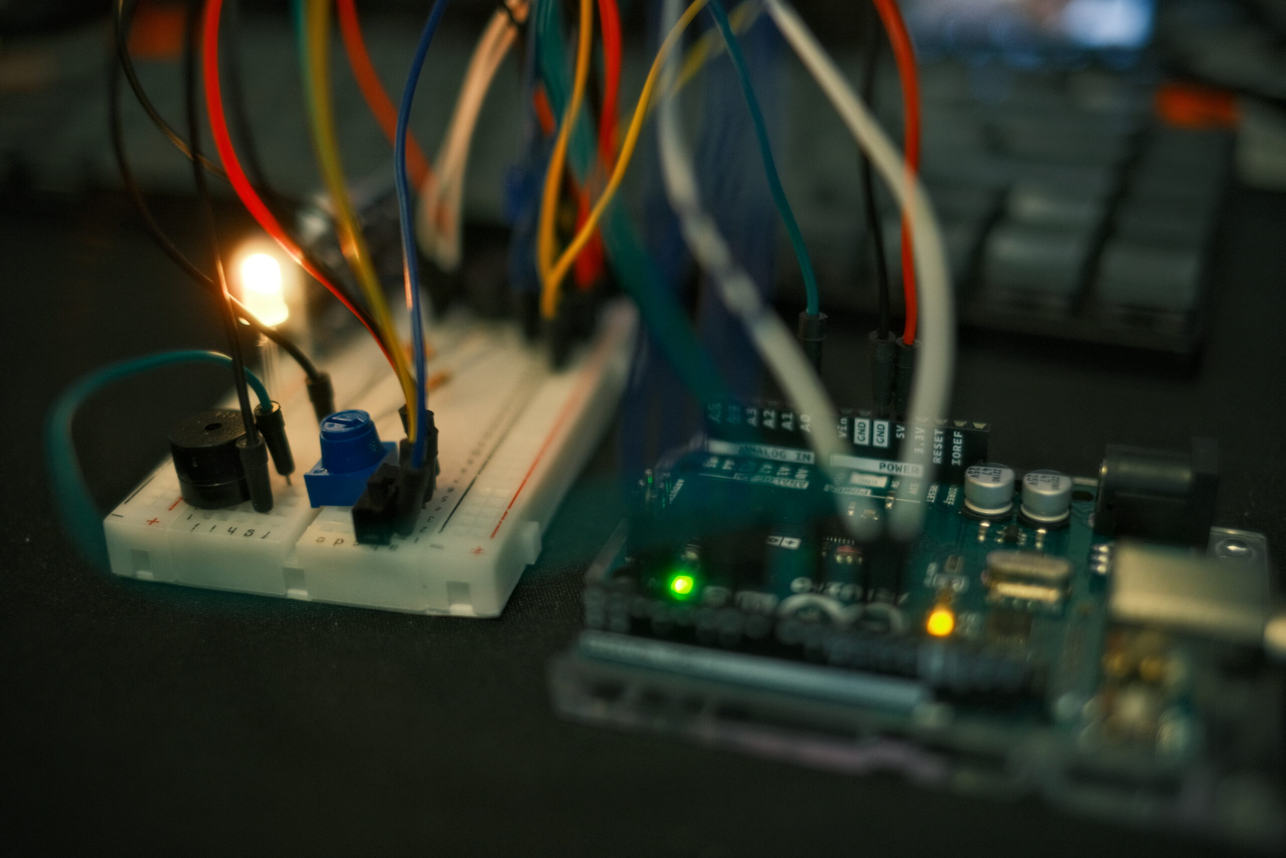
Building Arduino interface:


![]()
![]()
![]()
User Testing:
My friend Adi who has already taken this class and has experience in Interactive Media figured it out quite quickly. Before we even started, he told me he had worked with ML5 before and knew of its strengths and weaknesses and what to watch out for. Despite, this he still made some mistakes initially where he did not fully know how to do gestures. I showed him instruction paged and after confirming some of his doubts with hand orientations with me we started testing it second time where I tried to only explain after he did things on his own. He said it was pretty smooth and there were no major delays. I feel like one way to make this more clear for people unlike Adi who have never worked with ML5 before, is to instead of putting pictures and texts, record short GIFS or videos of visual demonstrations so they can see whats happening in 3 dimensions since the project itself is very much three dimensional. It will be interesting to see how people react to it during IM showcase which I will update in the respective section. Here is Adi’s second run:
More on: https://drive.google.com/drive/folders/1kAu8gpN6yCG0EfSr5FmAnB6liQApwaBf?usp=sharing
Implementation:
Interaction Design:
The interaction design revolves around using hand gestures to control various parameters of the visual art. Each gesture is mapped to a specific parameter, allowing the user to intuitively manipulate the shapes and patterns. For example, pinching the thumb and index finger together and moving the hand up and down controls the X-axis rotation. Conversely, thumb and middle finger controls number of shapes. Thumb and ring finger controls shape detail and thumb and pink changes perceived rotation speed (zAngle). Additionally, using two hands they can change zScale which visually demonstrates larger movement across Z, sort of like pulsing. Moving two hands like accordion further adds to fun and visual candy. Users can also use the physical box with three buttons and distance sensor to change zoom, toggle trail mode, stop/continue drawing and save a screenshot. The use of gestures makes the interaction more engaging and natural, enabling users to explore and experiment with the artwork in a hands-on manner.
Arduino Code:
const int trigPin = 9;
const int echoPin = 10;
const int buttonPin = 2;
const int ledPin = 13;
const int trailButtonPin = 4;
const int trailLedPin = 7;
const int screenshotButtonPin = 12;
const int screenshotLedPin = 8;
const int adminButtonPin = 6;

long duration;
int distance;
int buttonState = 0;
int trailButtonState = 0;
int screenshotButtonState = 0;
int adminButtonState = 0;

void setup() {
  pinMode(trigPin, OUTPUT);
  pinMode(echoPin, INPUT);
  pinMode(buttonPin, INPUT);
  pinMode(ledPin, OUTPUT);
  pinMode(trailButtonPin, INPUT);
  pinMode(trailLedPin, OUTPUT);
  pinMode(screenshotButtonPin, INPUT);
  pinMode(screenshotLedPin, OUTPUT);
  pinMode(adminButtonPin, INPUT);
  Serial.begin(9600);
}

void loop() {
  // Read distance from ultrasonic sensor
  digitalWrite(trigPin, LOW);
  delayMicroseconds(2);
  digitalWrite(trigPin, HIGH);
  delayMicroseconds(10);
  digitalWrite(trigPin, LOW);
  duration = pulseIn(echoPin, HIGH);
  distance = duration * 0.034 / 2; //calculate distanse
  distance = constrain(distance, 1, 20); //constraint

  // Read button states
  buttonState = digitalRead(buttonPin);
  trailButtonState = digitalRead(trailButtonPin);
  screenshotButtonState = digitalRead(screenshotButtonPin);
  adminButtonState = digitalRead(adminButtonPin);

  // Control LEDs based on button states
  digitalWrite(ledPin, buttonState);
  digitalWrite(trailLedPin, trailButtonState);
  digitalWrite(screenshotLedPin, screenshotButtonState);

  // Send data to p5.js
  Serial.print(distance);
  Serial.print(",");
  Serial.print(buttonState);
  Serial.print(",");
  Serial.print(trailButtonState);
  Serial.print(",");
  Serial.print(screenshotButtonState);
  Serial.print(",");
  Serial.println(adminButtonState);

  delay(100);
}
The Arduino code is responsible for reading data from the ultrasonic sensor and button states, and sending this information to the p5.js sketch. It continuously measures the distance using the ultrasonic sensor, which is then mapped to control the zoom level of the canvas. The code also reads the states of three buttons: a red button for toggling the trail mode, a yellow button for stopping the drawing, and a green button for taking a screenshot. The button states and distance data are sent to p5.js via serial communication.
Description of p5.js code:
The p5.js code handles the visual rendering and interaction of the artwork. It uses the ML5 library for hand pose detection, allowing the sketch to recognize and track hand gestures. The code maps each gesture to a specific parameter of the visual elements, such as X-axis rotation, number of shapes, shape detail, and Z-axis rotation. It also incorporates the data received from the Arduino, using the ultrasonic sensor readings to control the zoom level and the button states to toggle trail mode, stop drawing, and take screenshots. The code creates a dynamic and interactive experience by combining the hand gesture controls with the Arduino inputs.
I have three main sketch files. Sketch.js is the main one and is responsible for drawing the artwork as well as declaring, initializing variables, creating buttons, sliders, other helpers and toggles. It binds whole program together and keeps it running.
//Variables
let handPose; // ml5.js hand pose object
let video;
let hands = []; // stores hand data from the pose detector
let rotateXAngle = 60;
let rotateZAngle = 60;
let numShapes = 50; // number of geometric shapes displayed
let shapeDetail = 360 / 60;  // detail level of each shape
let radialScale = 3;
let zScale = 50;
let gestureActivated = false;
let zoom = 1;
let trailsEnabled = false;
let drawingEnabled = true;
let osc;
let adminMode = false; //for debugging + additional controls
let instructionsVisible = false;

//based on instruction on vs off
function updateButtonVisibility() {
  let buttons = selectAll('button:not(#backButton)');
  for (let i = 0; i < buttons.length; i++) {
    buttons[i].style('display', instructionsVisible ? 'none' : 'inline-block');
  }
}

function createInstructionsButton() {
  let buttonContainer = createDiv("");
  buttonContainer.style("position", "absolute");
  buttonContainer.style("right", "229px");
  buttonContainer.style("top", "20px");

  let instructionsButton = createButton("Instructions");
  instructionsButton.parent(buttonContainer);
  instructionsButton.id("instructionsButton");
  instructionsButton.mousePressed(toggleInstructions);
  styleButton(instructionsButton);
}

function toggleInstructions() {
  instructionsVisible = !instructionsVisible;
  updateButtonVisibility();
  updateAdminElements();
}

function hideInstructions() {
  instructionsVisible = false;
  updateButtonVisibility();
  updateAdminElements();
  backButtonPressed = true;
}


function createBackButton() {
  let buttonContainer = createDiv("");
  buttonContainer.style("position", "absolute");
  buttonContainer.style("left", "20px");
  buttonContainer.style("top", "20px");

  let backButton = createButton("↑");
  backButton.parent(buttonContainer);
  backButton.id("backButton");
  backButton.mousePressed(hideInstructions);
  styleButton(backButton);
}

function toggleAdminMode() {
  adminMode = !adminMode;
  updateAdminElements();
}

function updateAdminElements() {
  let elements = selectAll('button:not(#adminButton):not(#fullscreenButton):not(#instructionsButton):not(#backButton), input[type="range"]');
  for (let i = 0; i < elements.length; i++) {
    elements[i].style('display', adminMode && !instructionsVisible ? 'inline-block' : 'none');
  }
}

function createAdminButton() {
  let buttonContainer = createDiv("");
  buttonContainer.style("position", "absolute");
  buttonContainer.style("right", "20px");
  buttonContainer.style("top", "20px");

  let adminButton = createButton("Admin");
  adminButton.parent(buttonContainer);
  adminButton.id("adminButton");
  adminButton.mousePressed(toggleAdminMode);
  styleButton(adminButton);
}

function createFullscreenButton() {
  let buttonContainer = createDiv("");
  buttonContainer.style("position", "absolute");
  buttonContainer.style("right", "110px");
  buttonContainer.style("top", "20px");

  let fullscreenButton = createButton("Fullscreen");
  fullscreenButton.parent(buttonContainer);
  fullscreenButton.id("fullscreenButton");
  fullscreenButton.mousePressed(toggleFullscreen);
  styleButton(fullscreenButton);
}

function styleButton(button) {
  button.style("background-color", "#4CAF50");
  button.style("border", "none");
  button.style("color", "white");
  button.style("padding", "10px 20px");
  button.style("text-align", "center");
  button.style("text-decoration", "none");
  button.style("display", "inline-block");
  button.style("font-size", "16px");
  button.style("border-radius", "4px");
  button.style("cursor", "pointer");
}

function createSliders() { //visible in admin mode
  let sliderContainer = createDiv("");
  sliderContainer.id("sliderContainer");
  sliderContainer.style("position", "absolute");
  sliderContainer.style("left", "20px");
  sliderContainer.style("top", "20px");
  sliderContainer.style("display", "flex");
  sliderContainer.style("flex-direction", "column");

  let rotateZSlider = createSlider(10, 180, rotateZAngle);
  rotateZSlider.parent(sliderContainer);
  rotateZSlider.style("width", "200px");
  rotateZSlider.input(() => updateRotateZAngle(rotateZSlider.value()));

  let numShapesSlider = createSlider(10, 100, numShapes, 1);
  numShapesSlider.parent(sliderContainer);
  numShapesSlider.style("width", "200px");
  numShapesSlider.input(() => updateNumShapes(numShapesSlider.value()));

  let shapeDetailSlider = createSlider(3, 60, 6, 1);
  shapeDetailSlider.parent(sliderContainer);
  shapeDetailSlider.style("width", "200px");
  shapeDetailSlider.input(() => updateShapeDetail(shapeDetailSlider.value()));

  let radialScaleSlider = createSlider(1, 10, radialScale, 0.1);
  radialScaleSlider.parent(sliderContainer);
  radialScaleSlider.style("width", "200px");
  radialScaleSlider.input(() => updateRadialScale(radialScaleSlider.value()));

  let zScaleSlider = createSlider(10, 100, zScale, 1);
  zScaleSlider.parent(sliderContainer);
  zScaleSlider.style("width", "200px");
  zScaleSlider.input(() => updateZScale(zScaleSlider.value()));

  let zoomSlider = createSlider(0.1, 2, zoom, 0.1);
  zoomSlider.parent(sliderContainer);
  zoomSlider.style("width", "200px");
  zoomSlider.input(() => updateZoom(zoomSlider.value()));
}

function toggleFullscreen() {
  if (!document.fullscreenElement) {
    if (document.documentElement.requestFullscreen) {
      document.documentElement.requestFullscreen();
    } else if (document.documentElement.webkitRequestFullscreen) { // Safari
      document.documentElement.webkitRequestFullscreen();
    } else if (document.documentElement.msRequestFullscreen) { // IE/Edge
      document.documentElement.msRequestFullscreen();
    }
  } else {
    if (document.exitFullscreen) {
      document.exitFullscreen();
    } else if (document.webkitExitFullscreen) { // Safari
      document.webkitExitFullscreen();
    } else if (document.msExitFullscreen) { // IE/Edge
      document.msExitFullscreen();
    }
  }
}
function windowResized() {
  if (document.fullscreenElement) {
    resizeCanvas(windowWidth, windowHeight);
    instructionsGraphics.resizeCanvas(windowWidth, windowHeight * 2); //for fullscreen

  } else {
    resizeCanvas(windowWidth, windowHeight);
    instructionsGraphics.resizeCanvas(windowWidth, windowHeight * 2);

  }
}

function updatePitch(value) { //sound
  let freq = map(value, 1, 200, 50, 400);
  oscZScale.freq(freq);
  envZScale.play();
}

function updateFrequency(value) {  //different shape sound, reversed
  let freq = map(value, 10, 180, 400, 50);
  oscRotateZAngle.freq(freq);

}
function preload() {
  handPose = ml5.handPose();
  img1 = loadImage('gestures.png');
  img2 = loadImage('box.png');
}


function createScreenshotButton() {
  let buttonContainer = createDiv("");
  buttonContainer.style("position", "absolute");
  buttonContainer.style("left", "20px");
  buttonContainer.style("top", "260px");

  let screenshotButton = createButton("Take Screenshot");
  screenshotButton.parent(buttonContainer);
  screenshotButton.mousePressed(takeScreenshot);
}

function takeScreenshot() {
  saveCanvas('screenshot', 'png');
}

function setup() {
  createFullscreenButton();
  createCanvas(windowWidth, windowHeight, WEBGL);
  video = createCapture(VIDEO);
  video.size(640, 480); //og resolution
  video.style('transform', 'scale(-1, 1)'); //reverse if need to test video
  video.hide(); //if need to test for video
  handPose.detectStart(video, gotHands);
  angleMode(DEGREES);
  createSliders();
  createTrailButton();
  createStopDrawingButton();
  createScreenshotButton();
  oscZScale = new p5.Oscillator('triangle');
  oscRotateZAngle = new p5.Oscillator('sawtooth'); //waveform sawtooth
  oscZScale.amp(0.1);
  oscRotateZAngle.amp(0.1);

  envZScale = new p5.Envelope(); //used to ocntrol amplitude
  envZScale.setADSR(0.1, 0.2, 0.5, 0.5); //controls attack decay sustain and release
  envZScale.setRange(0.2, 0); //silence  after sustained phase

  oscZScale = new p5.Oscillator('triangle'); //waveform triangle
  oscZScale.start();
  oscZScale.amp(envZScale);

  // updateFrequency(rotateZAngle); //initial frequency
  updatePitch(zScale);
  createAdminButton();
  createBackButton();
  createInstructionsButton();
  updateButtonVisibility();
  updateAdminElements(); // make admin initially not visible
  instructionsGraphics = createGraphics(width, height * 2); //new graphics buffer for instructions
}
function keyPressed() { //spacebar to select serial port
  if (key === ' ') {
    setUpSerial();
  }
}

let backButtonPressed = false;

function draw() {
  if (!trailsEnabled || backButtonPressed) {
    background(30); //clear background
    backButtonPressed = false;
  }


  if (instructionsVisible) {
    // Clear the instructions graphics buffer
    instructionsGraphics.clear();
    instructionsGraphics.fill(0); //rectangle background black
    instructionsGraphics.noStroke();
    instructionsGraphics.rectMode(CORNER);
    instructionsGraphics.rect(0, 0, width, 2*height);
    instructionsGraphics.textAlign(LEFT, TOP); //align text

    // Adjust text size based on fullscreen mode
    let textSize = document.fullscreenElement ? 24 : 16;
    instructionsGraphics.textSize(textSize);

    instructionsGraphics.fill(255);

    // instruction paragraphs
    let paragraph1 = `Welcome to ThumbWave studio where you can explore interactive mathematical graphics with your hand gestures. Different hand gestures are assigned to different parameter. Holding your thumb and index finger together alters the tilt of the visuals, mimicking the effect of changing your perspective. Bringing your thumb and middle finger together adjusts the number of shapes on the display, allowing you to fill the screen with complexity or clear it for simplicity. Connecting your thumb to your ring finger modifies the intricacy of each shape, adding a layer of detail with further movements.`;
    let paragraph2 = `Keep in mind, while you hold these gestures you can change the value of individual parameter by moving your hand up and down (for X-axis rotation) or side to side (for the rest). Finally, a touch between your thumb and pinkie will spin the shapes around the Z-axis, injecting motion into the scene. For a more dramatic effect, use both hands as if handling an accordion: moving your hands together and apart changes the scale and depth of the shapes on the screen and alters the pitch of the background sounds to match your movements, enhancing the sensory experience.`;

    // each paragraph with appropriate spacing
    let padding = 20;
    let topPadding = 80; // top padding before the first paragraph
    let maxTextWidth = width * 0.9;
    let lineSpacing = document.fullscreenElement ? 60 : 50;

    drawParagraph(instructionsGraphics, paragraph1, padding, topPadding + padding, maxTextWidth, lineSpacing);
    let paragraph1Height = calculateParagraphHeight(instructionsGraphics, paragraph1, maxTextWidth, lineSpacing);

    // first image after the first paragraph
    let img1Width = width * 0.8;
    let img1Height = img1.height * (img1Width / img1.width);
    let img1X = (width - img1Width) / 2;
    let img1Y = topPadding + padding + paragraph1Height + lineSpacing;
    instructionsGraphics.image(img1, img1X, img1Y, img1Width, img1Height);

    drawParagraph(instructionsGraphics, paragraph2, padding, img1Y + img1Height + lineSpacing, maxTextWidth, lineSpacing);
    let paragraph2Height = calculateParagraphHeight(instructionsGraphics, paragraph2, maxTextWidth, lineSpacing);

    // second image after the second paragraph
    let img2Width = width * 0.8;
    let img2Height = img2.height * (img2Width / img2.width);
    let img2X = (width - img2Width) / 2;
    let img2Y = img1Y + img1Height + lineSpacing + paragraph2Height + lineSpacing;
    instructionsGraphics.image(img2, img2X, img2Y, img2Width, img2Height);

    let scrollPosition;
    if (document.fullscreenElement) {
      scrollPosition = map(mouseY, 0, windowHeight, 0, instructionsGraphics.height - windowHeight);
    } else {
      scrollPosition = map(mouseY, 0, height, 0, instructionsGraphics.height - height);
    }
    image(instructionsGraphics, -width / 2, -height / 2, width, height, 0, scrollPosition, width, height);


    //  the back button
    select("#backButton").style("display", "inline-block");
  } else { //dynamic rendering of 3D geometric shapes
    if (drawingEnabled) {
      push();
      scale(zoom);
      rotateX(rotateXAngle);
      noFill();
      stroke(255);
      for (let i = 0; i < numShapes; i++) { //dynamic color assignment
        let r = map(sin(frameCount / 2), -1, 1, 100, 200);
        let g = map(i, 0, numShapes, 100, 200);
        let b = map(cos(frameCount), -1, 1, 200, 100);
        stroke(r, g, b);
        rotate(frameCount / rotateZAngle); //rotate shape around z axis
        beginShape();
        for (let j = 0; j < 360; j += shapeDetail) { //3D cordinates for each vertex of shape
          let rad = j * radialScale;
          let x = rad * cos(j);
          let y = rad * sin(j);
          let z = sin(frameCount * 2 + i * 5) * zScale;
          vertex(x, y, z);
        }
        endShape(CLOSE);
      }
      pop();
    }

    // Hide the back button
    select("#backButton").style("display", "none");
  }
}

// Helper function to draw a paragraph of text
function drawParagraph(graphics, text, x, y, maxWidth, lineSpacing) {
  let words = text.split(' ');
  let currentLine = '';
  let yPos = y;
  //split text in individual words
  for (let i = 0; i < words.length; i++) {
    let word = words[i];
    let testLine = currentLine + ' ' + word; //add to current line
    let testWidth = graphics.textWidth(testLine);

    if (testWidth > maxWidth && currentLine !== '') { //exceed max
      graphics.text(currentLine, x, yPos); //we draw currentline on graphics
      currentLine = word;
      yPos += lineSpacing;
    } else {
      currentLine = testLine; //word added to current line
    }
  }
  graphics.text(currentLine, x, yPos); // draw the last line
}


function calculateParagraphHeight(graphics, text, maxWidth, lineSpacing) {
  let words = text.split(' ');
  let currentLine = '';
  let height = 0;


  for (let i = 0; i < words.length; i++) {
    let word = words[i];
    let testLine = currentLine + ' ' + word;
    let testWidth = graphics.textWidth(testLine);

    if (testWidth > maxWidth && currentLine !== '') {
      currentLine = word;
      height += lineSpacing; //increments height counter
    } else {
      currentLine = testLine;
    }
  }
  height += lineSpacing; // Add the last line's spacing
  return height;
}

function createStopDrawingButton() {
  let buttonContainer = createDiv("");
  buttonContainer.style("position", "absolute");
  buttonContainer.style("left", "20px");
  buttonContainer.style("top", "230px");

  let stopDrawingButton = createButton("Stop Drawing");
  stopDrawingButton.parent(buttonContainer);
  stopDrawingButton.mousePressed(toggleDrawing);
}
function toggleDrawing() {
  drawingEnabled = !drawingEnabled;
}

function createTrailButton() {
  let buttonContainer = createDiv("");
  buttonContainer.style("position", "absolute");
  buttonContainer.style("left", "20px");
  buttonContainer.style("top", "200px");

  let trailButton = createButton("Toggle Trails");
  trailButton.parent(buttonContainer);
  trailButton.mousePressed(toggleTrails);
}

function toggleTrails() {
  trailsEnabled = !trailsEnabled;
}

let rotateXAngleHistory = [];
let rotateXAngleHistorySize = 10;
let rotateXAngleSmoothingFactor = 0.2; //used for smoothing X with moving average


function updateRotateZAngle(value) {
  rotateZAngle = value;
  updateFrequency(value);
}

function updateNumShapes(value) {
  numShapes = value;
}

function updateShapeDetail(value) {
  shapeDetail = 360 / value;
}

function updateRadialScale(value) {
  radialScale = value;
}

function updateZScale(value) {
  zScale = value;
  updatePitch(value);
}

function updateZoom(value) {
  zoom = value;
}
The other file is gestures.js which is the heart of the project. It handles detection of gestures as I described above. It is commented well for general functions and you are free to inspect for particular mechanisms/logic.
function gotHands(results) {
  hands = results; //store data
  if (hands.length === 2) { //two hand detection
    let leftWrist = hands[0].keypoints[0];
    let rightWrist = hands[1].keypoints[0];
    //get wrist positions and then calculate wrist distanse
    let wristDistance = dist(leftWrist.x, leftWrist.y, rightWrist.x, rightWrist.y);

    let minDistance = 100;
    let maxDistance = 400;
    //normalize wrist constraints
    let mappedDistance = constrain(wristDistance, minDistance, maxDistance);
    let zScaleNew = map(mappedDistance, minDistance, maxDistance, 1, 200); //we map it to z scale
    zScale = zScaleNew; //update global value
    updatePitch(zScaleNew);
    if (adminMode) {
      console.log("Two hands gesture - zScale:", zScale);
    }
  } else if (hands.length > 0) { //if at least one is detected
    if (adminMode) {
      console.log("Pinch gesture - rotateXAngle:", rotateXAngle);
      console.log("Middle-thumb gesture - numShapes:", numShapes);
      console.log("Ring-thumb gesture - shapeDetail:", shapeDetail);
      console.log("Pinkie-thumb gesture - rotateZAngle:", rotateZAngle);
    }
    //fingertips for vairous gestures
    let indexFingerTip = hands[0].keypoints[8];
    let thumbTip = hands[0].keypoints[4];
    let pinchDistance = dist(indexFingerTip.x, indexFingerTip.y, thumbTip.x, thumbTip.y);

    let middleFingerTip = hands[0].keypoints[12];
    let middleThumbDistance = dist(middleFingerTip.x, middleFingerTip.y, thumbTip.x, thumbTip.y);

    let ringFingerTip = hands[0].keypoints[16];
    let ringThumbDistance = dist(ringFingerTip.x, ringFingerTip.y, thumbTip.x, thumbTip.y);

    let pinkieFingerTip = hands[0].keypoints[20];
    let pinkieThumbDistance = dist(pinkieFingerTip.x, pinkieFingerTip.y, thumbTip.x, thumbTip.y);

    //thumb to index gesture
    if (pinchDistance < 20) {
      gestureActivated = true;
      let wristY = hands[0].keypoints[0].y;
      let centerY = video.height * 0.6;
      let range = video.height / 10;
      let mappedY = constrain(wristY, centerY - range, centerY + range);
      let rotateXAngleNew = map(mappedY, centerY - range, centerY + range, 200, 0);

      rotateXAngleHistory.push(rotateXAngleNew);
      //we maintain history of rotateX angles to smoothen transition
      if (rotateXAngleHistory.length > rotateXAngleHistorySize) {
        rotateXAngleHistory.shift();
      }

      let rotateXAngleAverage = rotateXAngleHistory.reduce((sum, value) => sum + value, 0) / rotateXAngleHistory.length;

      rotateXAngle = lerp(rotateXAngle, rotateXAngleAverage, rotateXAngleSmoothingFactor);

    } else if (middleThumbDistance < 20) { //thumb gesture and middle finger
      let wristX = hands[0].keypoints[0].x;
      let centerX = video.width * 0.5;
      let range = video.width / 8;
      let mappedX = constrain(wristX, centerX - range, centerX + range);
      let numShapesNew = round(map(mappedX, centerX - range, centerX + range, 100, 1));
      numShapes = numShapesNew;

    } else if (ringThumbDistance < 20) { //ring and thumn gesture
      let wristX = hands[0].keypoints[0].x;
      let centerX = video.width * 0.5;
      let range = video.width / 8;
      let mappedX = constrain(wristX, centerX - range, centerX + range);
      let shapeDetailNew = round(map(mappedX, centerX - range, centerX + range, 3, 60));
      shapeDetail = 360 / shapeDetailNew;

    } else if (pinkieThumbDistance < 20) { //pinkie thumb gesture
      let wristX = hands[0].keypoints[0].x;
      let centerX = video.width * 0.5;
      let range = video.width / 8;
      let mappedX = constrain(wristX, centerX - range, centerX + range);
      let rotateZAngleNew = round(map(mappedX, centerX - range, centerX + range, 10, 180));
      rotateZAngle = rotateZAngleNew;
      updateFrequency(rotateZAngleNew);

    } else {
      gestureActivated = false;
    }
  }
}
Last but not least is the Arduino file. This code sets up and runs the serial communication between the Arduino and p5.js. It reads data from the Arduino, which includes the ultrasonic sensor distance and button states, and updates the corresponding variables in the p5.js sketch. The setUpSerial function initializes the serial communication, while the runSerial function continuously reads data from the serial port. The readSerial function parses the received data and updates the p5.js sketch accordingly. The distance value from the ultrasonic sensor controls the zoom level of the canvas using a smoothing technique. The button states toggle various functionalities, such as enabling/disabling drawing, trails, and taking screenshots. If adminMode is enabled, the code logs relevant information to the console for debugging purposes.
async function setUpSerial() {
  noLoop();
  ({ reader, writer } = await getPort());
  serialActive = true;
  runSerial();
  loop();
}

async function runSerial() {
  try {
    while (true) {
      if (serialActive) {
        const { value, done } = await reader.read();
        if (done) {
          reader.releaseLock();
          break;
        }
        readSerial(value);
      } else {
        break;
      }
    }
  } catch (e) {
    console.error(e);
  }
}

let zoomPrev = zoom;
let zoomSmoothingFactor = 0.1;
let zoomHistory = [];
let zoomHistorySize = 10;

let previousButtonState = 0;
let previousTrailButtonState = 0;
let previousScreenshotButtonState = 0;


let previousAdminButtonState = 0;


function readSerial(data) {
  let values = data.trim().split(",");
  if (values.length === 5) {
    let distance = parseInt(values[0]);
    let buttonState = parseInt(values[1]);
    let trailButtonState = parseInt(values[2]);
    let screenshotButtonState = parseInt(values[3]);
    let adminButtonState = parseInt(values[4]);

    if (!isNaN(distance) && !isNaN(buttonState) && !isNaN(trailButtonState) && !isNaN(screenshotButtonState) && !isNaN(adminButtonState)) {
      let zoomNew = map(distance, 1, 20, 4, 0.2);
      zoomHistory.push(zoomNew);
      if (zoomHistory.length > zoomHistorySize) {
        zoomHistory.shift();
      }
      let zoomAverage = zoomHistory.reduce((sum, value) => sum + value, 0) / zoomHistory.length;
      zoom = lerp(zoomPrev, zoomAverage, zoomSmoothingFactor);
      zoomPrev = zoom;
      if (adminMode) {
        console.log("Distance sensor - zoom:", zoom);
      }

      if (buttonState === 1 && previousButtonState === 0) {
        drawingEnabled = !drawingEnabled;
        if (adminMode) {
          console.log("Drawing state toggled:", drawingEnabled);
        }
      }
      previousButtonState = buttonState;

      if (trailButtonState === 1 && previousTrailButtonState === 0) {
        trailsEnabled = !trailsEnabled;
        if (adminMode) {
          console.log("Trails state toggled:", trailsEnabled);
        }
      }
      previousTrailButtonState = trailButtonState;

      if (screenshotButtonState === 1 && previousScreenshotButtonState === 0) {
        saveCanvas('screenshot', 'png');
        if (adminMode) {
          console.log("Screenshot taken");
        }
      }
      previousScreenshotButtonState = screenshotButtonState;
    }
  }
}
The communication between Arduino and p5.js:
As we said, the Arduino code sends the ultrasonic sensor distance and button states as a comma-separated string to p5.js. The p5.js code listens for the serial data and parses the received string to extract the distance and button states. This parsed data is then used to update the corresponding variables in the p5.js sketch, allowing the Arduino inputs to influence the visual output in real-time. The seamless communication between Arduino and p5.js enables the integration of physical interactions with the digital artwork.
Sketch Embed
Link for testing:
https://editor.p5js.org/dt2307/full/Gqx2rsti9L
What I am proud of:
I am proud of making ML5 integration with Handpose as smooth as it is. For the most part, the experience is seamless with minor delay. I am glad that visualization is working and due to the flexible nature of this project, this could be expanded to other mathematical demonstrations.
I am also proud of the fact that I did not necessarily fix myself to one idea. I experimented with both and found a way to combine them. Allowing users to not just test but also create something of their own is true interaction and I feel like this project accomplishes this task by integrating numerous hardware, software and design principles we learned in the class.
Resources I used:
For sine wave form visualizations I followed Colorful Coding videos: https://www.youtube.com/@ColorfulCoding
For general knowledge about ML5, I used ML5 project website: https://ml5js.org
For Handpose detection model, I used following Github repository with next gen ml5: https://github.com/ml5js/ml5-next-gen
For general principle, knowledge, troubleshooting – I used open web, provided slides and other available resources.
Challenges I faced and how I overcame them:
Throughout the development of this project, I encountered several challenges that tested my problem-solving skills and pushed me to think creatively. One of the main challenges I faced was ensuring a smooth and responsive interaction between the hand gestures and the visual elements. Initially, the gestures felt sluggish and unreliable, leading to a frustrating user experience. To overcome this, I spent a considerable amount of time fine-tuning the gesture recognition and mapping algorithms, experimenting with different thresholds and smoothing techniques. (Ended up with moving average method). Through trial and error, I managed to strike a balance between responsiveness and stability, resulting in a more intuitive and enjoyable interaction.
Another challenge I faced was different graphics buffers. Sometime’s drawings would get messed up and not display at all, or display on each other or not fully. Again it took lots of trials and errors but I eventually found what worked. There were several other minor bugs that might not have been immediately noticeable by users but I tried to polished them out so that whole experience remained coherent. Last aspect was just improving CSS and styling and make presentation visually pleasing. The audio aspect was also a bit confusing. I tried to keep constant audio but that got annoyed after a file. The dynamic audio which is only audible during logical (e.g. stretching across Z) movements is much more satisfying.
I also took a few suggestions from friends/professors to improve the interface. For example I added visuals to instructions page to make it more user friendly. Additionally I added a piece of plywood inside the box as a counterweight to keep the box from moving when users would press the buttons. Perhaps, cramming everything together in one box was the most nerve wracking part as I was using double sided tape and only had one shot at making it work. I planned it in my had many, many times before I actually committed to cutting out cardboard shapes and putting my components in without disconnecting. The most annoying issue I faced was perhaps something I could not control at all, because my USB hub, which never gives me issues, does not properly work with Arduino. Sometimes it just refused to work and I had to use other hubs when it would miraculously start working again.
Areas for Future Improvement:
There are several directions this project can be extended in. Firstly, I would love to integrate more advanced machine learning algorithms or perhaps one day learn to write one myself to make the whole experience even smoother. With more accurate detection, you could get even more nuanced gestures which could further ameliorate user experience and make the whole process run faster.
Additionally, I would like to expand and add more mathematical models for this project and its educational context. Perhaps by making modular design, I could let users pick their desired mathematical or other science based concepts from biology or chemistry and have their own visualization running in as little time as possible. They could assign their own parameters and have more flexibility with all the movements. Perhaps, having a more advanced model would also help with more than one person demonstrations, where multiple people can engage with single visualization, either by observing it or by producing their own art. Of course, polishing current code, improving casing for Arduino, adding more sensors are all viable avenues as well. It would be cool to add vibration motors so users could also feel the movement in real time, making the experience much more tactile and intuitive.
In the end, I am very glad with how my project turned out and despite facing numerous challenges, overall I had a lot of fun and would love to come up with more creative projects like this in the feature. Hope you guys liked it too!