
Concept
For this week’s assignment, I drew inspiration from Mood Lamps. Mood Lighting helps create a calming and soothing atmosphere and can invoke different moods depending on the colors you set it at. I’ve tried to create a very basic version of this.
Process
My idea was to use an RGB Led, a digital switch for digital input and a potentiometer for analog input for this. However, certain values of potentiometer readings did not work and hence I added separate green and yellow LEDs that would light up instead. There is a circular ring of moods around the potentiometer. You can move the arrow towards the m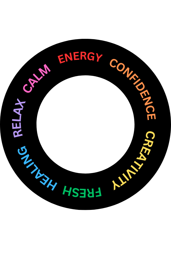 ood you’d like to set it up at. The potentiometer values are mapped to rgb values that are then displayed on the RGB Led. If the digital switch is pressed, alot of colors get displayed automatically. In this case the mapping is between time and the rgb values
I had some trouble figuring out the working of the digital switch but with some references and trial and errors, I eventually figured it out to work somewhat like desired.
code:
void setup() {
  pinMode(RGB_RED_PIN, OUTPUT);
  pinMode(RGB_BLUE_PIN, OUTPUT);
  pinMode(RGB_GREEN_PIN, OUTPUT);
  pinMode(GREEN_LED_PIN, OUTPUT);
  pinMode(YELLOW_LED_PIN, OUTPUT);
  pinMode(SWITCH_PIN, INPUT);

  Serial.begin(9600);
}

void loop() {
  int switchState = digitalRead(SWITCH_PIN);
    Serial.print("Switch State: ");
Serial.println(switchState);

  if (switchState == HIGH) {

     int currentTime = millis();
  int period = 3;
  int rgbValue = map(currentTime % period, 0, period, 0, 1535);

  // convert the RGB value to individual color components
  int red, green, blue;

  if (rgbValue < 256) {
    red = 255;
    blue = rgbValue;
    green = 0;
  } else if (rgbValue < 512) {
    red = 511 - rgbValue;
    blue = 255;
    green = 0;
  } else if (rgbValue < 768) {
    red = 0;
    blue = 255;
    green = rgbValue - 512;
  } else if (rgbValue < 1024) {
    red = 0;
    blue = 1023 - rgbValue;
    green = 255;
  } else if (rgbValue < 1280) {
    red = rgbValue - 1024;
    blue = 0;
    green = 255;
  } else {
    red = 255;
    blue = 0;
    green = 1535 - rgbValue;
  }

  // setting RGB LED colors
  analogWrite(RGB_RED_PIN, red);
  analogWrite(RGB_BLUE_PIN, blue);
  analogWrite(RGB_GREEN_PIN, green);


    // separate green LED
    digitalWrite(GREEN_LED_PIN, HIGH);

    //separate yellow LED
    digitalWrite(YELLOW_LED_PIN, LOW);
  } else {
  int potentiometerValue = analogRead(POTENTIOMETER_PIN);
  int rgbValue = map(potentiometerValue, 0, 1023, 0, 1535);

  // potentiometer value to the serial monitor
  Serial.print("Potentiometer Value: ");
  Serial.println(potentiometerValue);

  int red;
  int blue;
  int green;

  if (rgbValue < 256) {
    red = 255;
    blue = rgbValue;
    green = 0;
  }
  else if (rgbValue < 512) {
    red = 511 - rgbValue;
    blue = 255;
    green = 0;
  }
  else if (rgbValue < 768) {
    red = 0;
    blue = 255;
    green = rgbValue - 512;
  }
  else if (rgbValue < 1024) {
    red = 0;
    blue = 1023 - rgbValue;
    green = 255;
  }
  else if (rgbValue < 1280) {
    red = rgbValue - 1024;
    blue = 0;
    green = 255;
  }
  else {
    red = 255;
    blue = 0;
    green = 1535 - rgbValue;
  }

  analogWrite(RGB_RED_PIN, red);
  analogWrite(RGB_BLUE_PIN, blue);
  analogWrite(RGB_GREEN_PIN, green);

  // separate green and yellow LEDs based on potentiometer value
  if (potentiometerValue >= 340 && potentiometerValue <= 510) {
    digitalWrite(GREEN_LED_PIN, HIGH);  // Turn on green LED
    digitalWrite(YELLOW_LED_PIN, LOW);  // Turn off yellow LED
  } else if (potentiometerValue >= 165 && potentiometerValue <= 342) {
    digitalWrite(GREEN_LED_PIN, LOW);   // Turn off green LED
    digitalWrite(YELLOW_LED_PIN, HIGH);  // Turn on yellow LED
  } else {
    digitalWrite(GREEN_LED_PIN, LOW);   // Turn off green LED
    digitalWrite(YELLOW_LED_PIN, LOW);  // Turn off yellow LED
  }

  delay(100);
  }

  // delay to avoid flooding the serial monitor with data
  delay(100);
}
Reflections
I really enjoyed this and was able to explore different sensors as I tried out the ultrasonic resistor, potentiometer and photoresistor before deciding which one to go forward with. I did have some issues while coding but managed to make something similar to what I had expected. For future improvements, I could maybe use something transparent/translucent to cover the leds and make the light intensify more like in usual lamps.
References