
Ramp Lights!
This week we learned how to control and manipulate digital and analog input/outputs on Arduino IDE. It was interesting how a few lines of code with basic instructions could control a physical output like an LED. For the assignment, I created a ramp light sequence (imagine lights turning on one by one on a ramp, tried to recreate that). The lights turn on sequentially with the rotation of a potentiometer. Here’s a video of how that turned out:
How it works:
The working of this is very simple: the potentiometer has values calibrated with its rotation, so I took those values as input and using if and else if conditions, I changed the state of the LEDs to HIGH or LOW.
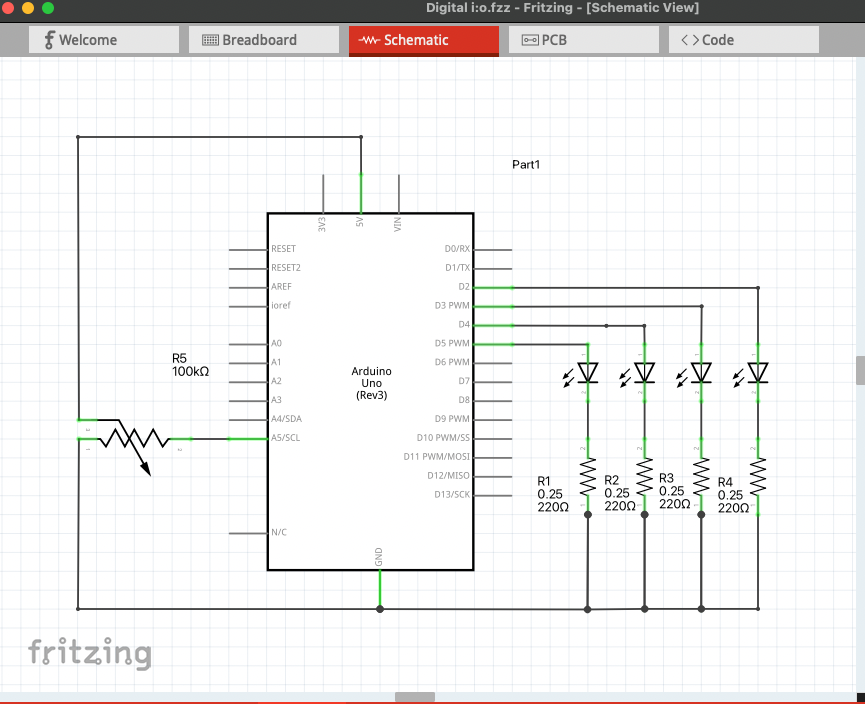
The Schematics:
Here’s a diagram of the schematics made using Fritzing:
Arduino IDE code:
int potPin = A5;
int ledPin1 = 2;
int ledPin2 = 3;
int ledPin3 = 4;
int ledPin4 = 5;

void setup() {

  pinMode(potPin, INPUT);
  pinMode(ledPin1, OUTPUT);
  pinMode(ledPin2, OUTPUT);
  pinMode(ledPin3, OUTPUT);
  pinMode(ledPin4, OUTPUT);
  Serial.begin(9600);

}

void loop() {
  int potValue = analogRead(A5);
  Serial.println(potValue);

  if (potValue < 100) {
    digitalWrite(ledPin1, LOW);
    digitalWrite(ledPin2, LOW);
    digitalWrite(ledPin3, LOW);
    digitalWrite(ledPin4, LOW);
  }

  else if (potValue < 256) {
    digitalWrite(ledPin1, HIGH);
    digitalWrite(ledPin2, LOW);
    digitalWrite(ledPin3, LOW);
    digitalWrite(ledPin4, LOW);

  }


  else if (potValue < 512) {
    digitalWrite(ledPin1, HIGH);
    digitalWrite(ledPin2, HIGH);
    digitalWrite(ledPin3, LOW);
    digitalWrite(ledPin4, LOW);
  }

  else if (potValue < 768) {
    digitalWrite(ledPin1, HIGH);
    digitalWrite(ledPin2, HIGH);
    digitalWrite(ledPin3, HIGH);
    digitalWrite(ledPin4, LOW);
  }

  else if (potValue < 1024) {
    digitalWrite(ledPin1, HIGH);
    digitalWrite(ledPin2, HIGH);
    digitalWrite(ledPin3, HIGH);
    digitalWrite(ledPin4, HIGH);
  }


}
It was fun creating the ramp lights and seeing the lights turn on/off with the turn of my potentiometer!