
🤯 Idea
While thinking about this assignment, I wanted to make something tangible that would actually feel like musical instrument and act like one too. Initially, I gravitated towards trying to make a sort of MIDI player because I wanted to press a button that would play a beat and another one to layer the first beat with another beat (sort of like the Groovepad App) but after many failed attempts I realized that it was quite hard to create a harmony using the buzzer and so eventually I had to abandon the idea. However, I kept up with the spirit and then thought of mimicking an electric bass guitar using the Arduino and I feel I was somewhat able to do it but not completely because of certain difficulties which I will be explaining later on.
🤩 Implementation
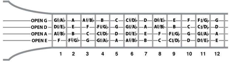
So the way I saw it, the electric bass seemed to be the most convenient instrument to implement through the Arduino as all it consists of is 4 strings and 12 sections along with the sound of just playing the strings. Obviously, mimicking the strumming patterns of the bass would be unfeasible or too time taking for this assignment but at least I could mimic the act of playing the individual notes. And I did so by first storing the notes in a 2D array based on how they are arranged in a bass guitar (see image below) and then having the four buttons mimic the four strings and using the potentiometer as a tool to change between sections. For added ease, I also added LED lights that would turn on when you are in a particular section so that you could get the experience of playing notes on a bass. Basically I replace the act of putting your finger on the string with pressing a button and then choosing a note by moving your finger along the string with choosing a note by turning a potentiometer.
This was the circuitry involved to implement this assignment
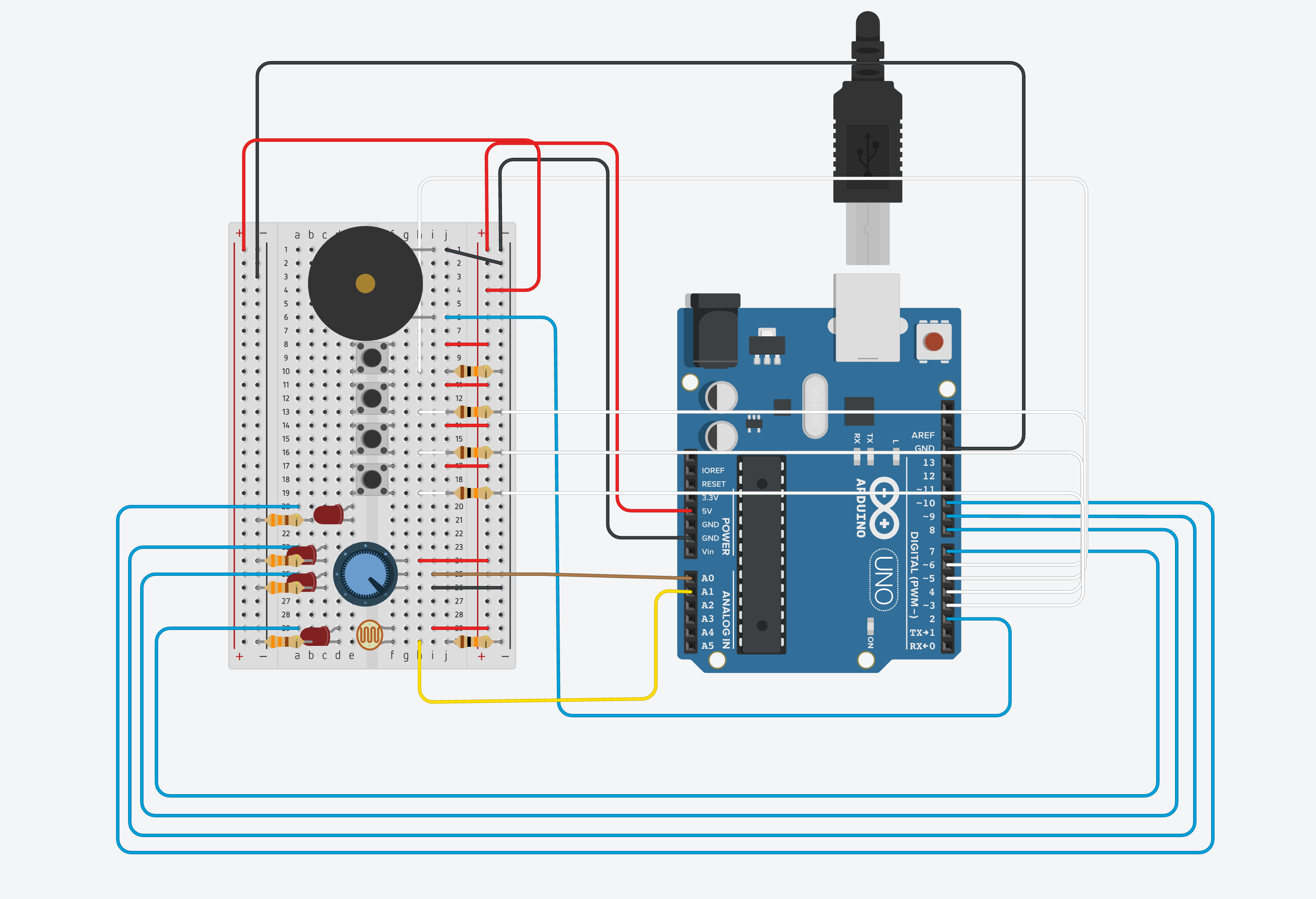
As you can see there are four LEDs involved with the one connected to the 7th Pin signifying that this is the open string being played on the bass. The LED connected to 8th pin is for strings from 1-4 and the one connected to the 9th Pin is for strings from 5-8. The last LED is for strings from 9-12. Initially I wanted to have a separate LED for each string but this was not possible due to the small size of the board.
There are four buttons connected that operate as the strings
A potentiometer to change between notes within a string.
A buzzer that emits sound.
A photo-resistor (of which I will talk in the difficulties section).
The code:
#include "pitches.h"

const int NO_PINS = 4;
const int NO_BUTTONS = 4;
const int STRINGS = 4;
const int SECTIONS = 13;
const int BUZZER_PIN = 2;

int notes[STRINGS][SECTIONS] = {NOTE_E5, NOTE_F5, NOTE_FS5, NOTE_G5, NOTE_GS5, NOTE_A5, NOTE_AS5, NOTE_B5, NOTE_C6, NOTE_CS6, NOTE_D6, NOTE_DS6, NOTE_E6,
                          NOTE_A4, NOTE_AS4, NOTE_B4, NOTE_C4, NOTE_CS4, NOTE_D4, NOTE_DS4, NOTE_E4, NOTE_F4, NOTE_FS4, NOTE_G4, NOTE_GS4, NOTE_A4,
                            NOTE_D3, NOTE_DS3, NOTE_E3, NOTE_F3, NOTE_FS3, NOTE_G3, NOTE_GS3, NOTE_A3, NOTE_AS3, NOTE_B3, NOTE_C3, NOTE_CS3, NOTE_D3,
                          NOTE_G2, NOTE_GS2, NOTE_A2, NOTE_AS2, NOTE_B2, NOTE_C2, NOTE_CS2, NOTE_D2, NOTE_DS2, NOTE_E2, NOTE_F2, NOTE_FS2, NOTE_G2 };   // THE NOTES AS ON THE BASS

int whichNote = 9;
int buttonPins[NO_BUTTONS] = {3,4,5,6};
int ledPins[NO_PINS] = {7,8,9,10};
int ledSwitches[NO_PINS];
int currentButtonState[NO_BUTTONS];
int previousButtonState[NO_BUTTONS];
int whichString;

void setup() {
  Serial.begin(9600);

  for(int i = 0; i< NO_PINS; i++)
  {
  pinMode(ledPins[i], OUTPUT);   //SETTING OUTPUT PINS
  }

  for(int i = 0; i< NO_BUTTONS; i++)
  {
  pinMode(buttonPins[i], INPUT);  //SETTING INPUT PINS
  }

  for(int i = 0; i< NO_BUTTONS; i++)
  {
  previousButtonState[i] = 0;  //SETTING ALL PREVIOUS BUTTONS TO OFF
  }


void loop() {


  int knobValue = analogRead(A0);
  int whichSection = map(knobValue, 0, 1023, 0, 12);
 // SECTION SPECIFIC LIGHTING OF LEDs
  if(whichSection == 0){
    ledSwitches[0] = 1;
    ledSwitches[1] = 0;
    ledSwitches[2] = 0;
    ledSwitches[3] = 0;
  }
  if(whichSection > 0 && whichSection < 5){
    ledSwitches[0] = 0;
    ledSwitches[1] = 1;
    ledSwitches[2] = 0;
    ledSwitches[3] = 0;
  }
  if(whichSection > 4 && whichSection < 9){
    ledSwitches[0] = 0;
    ledSwitches[1] = 0;
    ledSwitches[2] = 1;
    ledSwitches[3] = 0;
  }
  if(whichSection > 8 && whichSection < 13){
    ledSwitches[0] = 0;
    ledSwitches[1] = 0;
    ledSwitches[2] = 0;
    ledSwitches[3] = 1;
  }

  for (int i =0; i<NO_PINS; i++)
  {
    digitalWrite(ledPins[i],ledSwitches[i]);
  }


// SWITICHING THE BUTTON ON OR OFF TO OBTAIN THE STRING

  for(int i = 0; i< NO_BUTTONS; i++)
  {
  currentButtonState[i] = digitalRead(buttonPins[i]);
  Serial.println(currentButtonState[i]);
    if (currentButtonState[i] == 1 && previousButtonState[i] == 0){
      whichString = i;
//    tone(BUZZER_PIN, notes[whichString][whichSection], 400);      OPTION 2
//    delay(1);
  }
  previousButtonState[i] = currentButtonState[i];
  }


  int volumeValue = analogRead(A1);    //ATTEMPT AT MANIPULATING VOLUME
  int pwm = map(volumeValue, 54, 970, 0, 125);

  unsigned long currentTime = millis();


    tone(BUZZER_PIN, notes[whichString][whichSection], 50);
    delay(1);    //                                                 OPTION 1
    //analogWrite(11,pwm);
 // }

}
🧐 Process
While coding this project, I was confused on two design choices available to me. In the first one, the notes would be continuous and would not stop but just change. In the second one, the notes could only be heard if the button was pressed. In the end I could not make up by mind and so decided to showcase both of them instead 🙂
👀 Demo
This is the youtube video where I go in depth about the project (sorry for the length!).
😅 Difficulties and what’s next
At first, along with the whole bass guitar idea, I had also decided to add a feature in which you could control the volume of the tone being played out and after seeing a bunch of YouTube videos on it, I thought I would give it a shot. However, even after multiple events I was not able to implement it. I had thought of using the photo-resistor for this but either the wires would come along the way or the lights were not easy to manoeuvre, something or the other would not let the whole thing happen smoothly.
Another big issue was the smoothening of the tone heard, as is evident from the video, when I try the first method, the 8bit tune can get really annoying after sometime and so I would want to figure out how I can eliminate that, whenever I work on this project again.
🥳 But overall, it was quite fun and learned a lot about the tone reference and understood the concepts of the buttons, LED, potentiometer and even the electricity flowing in the circuit, much better!
Nice job Armaan. I like the user interface you built with the LEDs. Seems like maybe there was something a little buggy with that last button? I want to see a performance now!