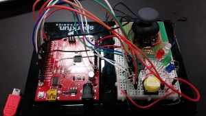
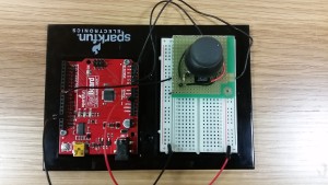
Given that our task was to fiddle with analog inputs, I figured I could just experiment and do cool stuff using a joystick – also known as an analog stick for a reason. In the end, I connected a joystick to a breadboard in order to control the pitch of a buzzer and the color of an RGB LED!
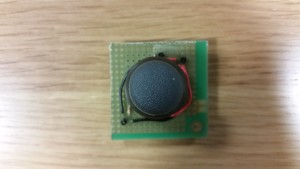
First, I had to connect the joystick to my boards. In essencem a joystick is nothing more than two potentiometers nicely put together such that one turns vertically and the other horizontally. Some joysticks (like this one) also have a push button integrated, which gives me a total of three outputs to use. The problem was that, though the joystick comes with some nice pins to plug it into stuff, some of them don’t really line up very nicely with the breadboard. So I had to take another board, plug the joystick there, solder a lot of stuffs, burn my finger, make sure the stuffs were lined up nicely, and finally plug that into the breadboard. It was a lot fo work but it was fun as well!
Once I had tested that all the connections were properly in place and that the joystick ACTUALLY worked, it was time to make the joystick do something. I wanted, in a way, to build upon my last project, so I decided to have again two modes. This time, however, both would be on the same program and one would be able to switch between them with a button (yay!). To make this work, I wrote each mode within a separate while() statement. while() makes the program run the code that is inside it only while the argument to be tested is true. This means you need a way to change that argument from within the while() or your program might be stuck there forever. To test this functionality, I tried using the while() loops to turn on two LEDs, while referring to the class example to make the switch only be pressed once:
int mode = 0; //To select mode
int prevButton = 0; //To avoid mode button double clicks

void setup() {
  // put your setup code here, to run once:
  pinMode(2, INPUT); //Button input
  pinMode(3, OUTPUT);
  pinMode(4, OUTPUT); //LED outputs
}

void loop() {
  int button; //Stores current state of mode button
  //while() loop sets two different loops to follow, depending on the mode selected
  while (mode == 0) {
    button = digitalRead(2); //Read if button is pressed
    digitalWrite(3, HIGH);
    digitalWrite(4, LOW); //Ultra-bright red LED lights up on the side of the selected mode
    //This if() statement controls the change of mode while avoiding double clicks
    if (button == HIGH && button != prevButton) {
      mode = 1;
    }
    prevButton = button; //Update previous state of button to current one after comparing
  }
  while (mode == 1) {
    button = digitalRead(2);
    digitalWrite(4, HIGH);
    digitalWrite(3, LOW);
    //if() statement to change mode, ditto the one above
    if (button == HIGH && button != prevButton) {
      noTone(5);
      start = 0;
      mode = 0;
    }
    prevButton = button;
  }
}
Once that was out of the way, I just had to program the actual things inside each while() statement.
For the buzzer, I had to use tone(). This finction changes the frequency of an output, allowing you to play different sounds in the buzzer:
// tone(pin, frequency, duration[optional])
//For example:

void setup(){
    pinMode(5, OUTPUT);
    }

void loop(){
    tone(5, 523.25, 200);
    delay(200);
    tone(5, 783.99, 200);
    delay(200);
    tone(5, 659.25, 400);
    delay(400);
    }

//Gives you a little tune if you connect a buzzer to pin 5
You can also make the buzzer shut up with noTone(pin). I also decided to create my own function to translate the linear change in resistance of the joystick into an exponential scale in order to simulate two octaves with the joystick (because pitch doesn’t change linearly).
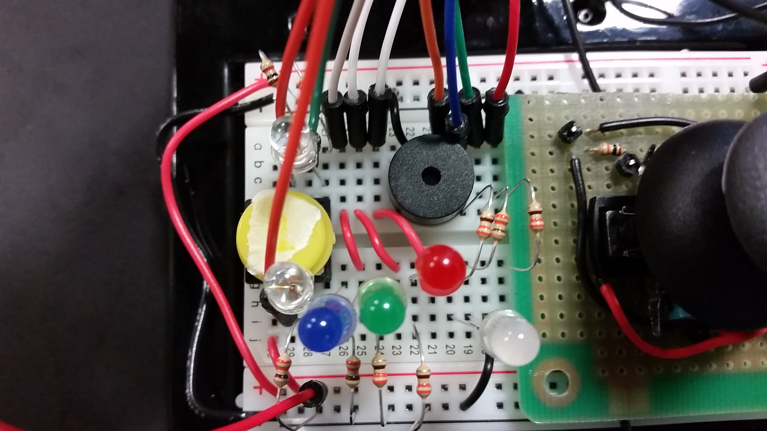
To adjust the RGB LED’s color, I had to make use of a switch() case statement and analogWrite() (PWM). switch() lets you check a variable and execute different things depending on the variable’s value. For instance, I wired a LED of each color to signify which color is being “edited” by the joystick using switch():
//switch(variable) case statement allows me to set different instructions for different values of color
    switch (color) {
      //9 is for RED
      case 9:
        digitalWrite(6, HIGH); //Red LED
        digitalWrite(7, LOW); //Green LED
        digitalWrite(12, LOW); //Blue LED
        break; //break allows us to exit the case and keep comparing color
      //10 is GREEN; ditto for all said in RED
      case 10:
        digitalWrite(6, LOW);
        digitalWrite(7, HIGH);
        digitalWrite(12, LOW);
        break;
      //11 is BLUE
      case 11:
        digitalWrite(6, LOW);
        digitalWrite(7, LOW);
        digitalWrite(12, HIGH);
        break;
    }
Using analogWrite() I set the intensity of each color in the RGB LED. However, instead of making the analog input directly determine the ouput, I used the input to change the output incrementally. That is, tilting the joystick would increase/decrease the intensity of the color, but if letf untouched the intensity wouldn’t change. (In contrast, for the buzzer I made the pitch directly dependent on the joystick: full up, full down and center had each a preset pitch, and intermediate tilts had the values in between.)
And voilà! Here’s the end result! 😀